Note: Descriptions are shown in the official language in which they were submitted.
CA 02755008 2011-09-15
WO 2010/107549 PCT/US2010/024728
METHOD AND APPARATUS FOR DELIVERING
A SHAPE MEMORY ARTICLE TO A SURGICAL SITE
CROSS-REFERENCE TO RELATED APPLICATIONS
[0001] This application claims priority to provisional patent Application No.
61/161,604, filed March 19, 2009, the disclosure of which is hereby
incorporated
herein by reference.
BACKGROUND OF THE INVENTION
[0002] Shape memory articles (SMAs), comprised, for instance, substantially
of NiTinol alloy, are used in many surgical applications, including use as
staples
for re-attaching tissue or bone. Usually, external heat is applied to the
shape
memory article in order to transition it from a first shape in a martensitic,
softer,
morphology to a second shape in an austentitic, stiffer, morphology.
[0003] When a patient suffers an injury in which tissue or bone must be
reapproximated, reattached, or fused, the injury often must be repaired by
surgically securing the tissue or bone together with internal fixation devices
such
as plates, screws, pins, or staples. These devices are often rigid and have
geometric features that enable them to reapproximate, reattach, or fuse
tissues.
Examples of these features include threads, grooves, overall shape of the
device, and other features that provide attachment or support. Any undesired
deformation of these devices could lead to increased amounts of strain and
ultimate failure of the device.
[0004] Since the late 1980's, NiTinol, a Nickel-Titanium alloy, has been
increasingly utilized in a variety of medical devices and, in some cases, has
become one of the materials of choice for many designers and engineers. From
surgical devices to endoluminal stents and other prostheses, the thermo-
mechanical characteristics of the material and its biocompatibility have
allowed
its use across many medical and surgical specialties both for diagnostic and
therapeutic applications.
1
CA 02755008 2011-09-15
WO 2010/107549 PCT/US2010/024728
[0005] The shape memory effect results from a reversible crystalline phase
change known as martensitic transformation. Shape memory alloys can display
various types of shape memory. The type of shape memory that has probably
found the most use in commercial applications is commonly referred to as one-
way shape memory. In one-way shape memory, an article formed of a shape
memory alloy in an original shape can be substantially plastically deformed
into a
shape while it is in the soft, martensitic phase and it will remain in that
shape,
(hereinafter the deformed shape). Then, upon heating above a first
temperature,
the material returns to its original (prior to deformation) shape while
transitioning
from the soft, martensitic phase to a much stiffer austentitic phase. It
should be
noted that, while the article is much stiffer in the austentitic phase, it
usually is
still somewhat deformable, but primarily elastically, as opposed to
plastically,
deformable. Upon cooling below a second temperature that is below the first
temperature, the material transitions back to the softer, martensitic phase,
but
maintains the shape it took during the transformation to the austentitic phase
(i.e., its original shape) until it is acted upon by an external force or
stress.
Because the material is less stiff (i.e., more pliable) in its martensitic
phase, it is
much easier to bend (back to the deformed shape or any other shape) and it
will
maintain that new shape up to and until it is heated once more above its
transformation temperature.
[0006] The strength and transition temperatures of SMAs can be greatly
varied by changing the exact composition of the alloy and/or the thermal
history
of the article.
[0007] The use of shape memory staples in surgical skeletal repair enables a
staple to be installed in bone or tissue in one shape while in its martensitic
phase
and then be heated to cause it to transition to the much stiffer austentitic
phase
while shifting to another shape that, for instance, draws the tissue or bone
closer
together. Many medical applications use SMAs having a transition temperature
for complete martensitic to austentitic transformation of about 55 C. However,
other medical applications utilize alloys having a complete transition
temperature
at about human body temperature of 37 C.
2
CA 02755008 2011-09-15
WO 2010/107549 PCT/US2010/024728
[0008] While metallic staples have long been used for static fixation, the use
of shape memory alloys (SMAs) in staples and their attendant ability to apply
dynamic continuous compression is a major advancement in tissue and bone
uniting that potentially improves the healing process in connection with the
repair,
fusing, and remodeling of damaged tissue. These SMA staples are smaller and
less bulky than other fixation devices, such as plates, screws, and nails.
They
permit smaller incisions, which cause less trauma and scarring and lead to
faster
post-operative recovery. Also, since fewer holes need to be drilled and no
screws
are needed, more rapid surgical procedures are possible.
[0009] The shape memory properties described hereinabove are sometimes
referred to as superelasticity, particularly when the transition from
martensitic
phase to austentitic phase occurs at lower temperatures, such as room
temperature or below. The terminology is not consistent in the art. In this
specification, we shall simply use the term shape memory generically as
encompassing superelasticity.
[0010] Figure 1 is a graph showing a dynamic scanning calorimetry (DSC) for
one particular NiTinol composition. DSC is useful for determining the
temperatures at which various substances undergo phase changes. In the case
of NiTinol or other SMA articles, DSC is utilized to understand the
temperatures
required for transitioning from the martensitic phase to the austentitic phase
and
back again. DSC measures the heat flow necessary to maintain the article at a
certain temperature. The bottom portion of the scan represents the state of
the
article at -500C as it is subjected to increasing temperature over time. This
graph
shows a stable structure (martensitic morphology) during temperatures up to an
austentitic start temperature (As) of approximately 29 C, where phase
transformation to the austentitic phase theoretically begins. As demonstrated
by
this scan and the change in heat flow, the metal is fully transformed into its
stiff,
austentitic phase at the austentitic finish temperature (Af) of approximately
500C.
The top portion of this scan represents cooling of the austentitic NiTinol
article
starting at 100 C. Note that the martensitic phase recovery theoretically
begins at
the martensitic start temperature (Ms) of approximately 19 C and is complete
at
3
CA 02755008 2011-09-15
WO 2010/107549 PCT/US2010/024728
the martensitic finish temperature of approximately 0 C. This is only an
example
of one form of NiTinol shape memory alloy. Other transition temperatures are
achievable with different chemical compositions and thermo-mechanical
treatments.
[0011] Using the exemplary material above, one can see that the device is
geometrically stable in its martensitic phase up to room temperature, can be
transformed to an austentitic phase via heating it to around 55 C and that it
stays
in a stable austentitic phase down to temperatures well below body
temperature.
This is very advantageous in surgical applications as devices, such as
orthopaedic staples, can be programmed during manufacture with a clinical
utility
shape in the austentitic phase (the shape that it will take after heating
during a
surgical procedure) and then be deformed during manufacturing to an operable
configuration in its martensitic phase (the shape in which it will be
delivered to
the surgeon for insertion into the body prior to heating).
[0012] Orthopaedic NiTinol staples have been available clinically in the US
for approximately ten years. The manufacturers of these devices are using
various instruments and power sources for heating the staples in order to
effect
the transformation to the austentitic phase in vivo. Tissue cautery and
coagulation devices typically are available in an operating theater and are
commonly used to provide heat to shape memory articles.
[0013] Shape memory materials typically have a temperature range of about
20 C over which they make the transformation from the martensitic phase to the
austentitic phase. Thus, for instance, a shape memory article designed to
complete its transformation to the austentitic phase at body temperature,
i.e.,
about 37 C, will begin transitioning at temperatures as low as 17 C, or at
approximately room temperature.
[0014] Thus, shape memory articles, particularly ones designed for body
temperature activation often are exposed to temperatures higher than the
temperature at which they start the phase change from martensitic to
austentitic
phase prior to surgery, such as during transportation. Accordingly, shape
4
CA 02755008 2011-09-15
WO 2010/107549 PCT/US2010/024728
memory articles often are packaged in the manufacturing plant in a
constraining
device that prevents them from changing shape until released from the
constraining device.
[0015] Once a shape memory article has transformed to its austentitic phase,
it can be transformed back to martensitic by exposing the shape memory article
to a much lower temperature. In the example above, such a transition
temperature back to the martensitic phase would occur at or below (minus)15 C.
thus, immediately prior to surgery, shape memory articles commonly are frozen
to return them as fully as possible to their original martensitic phase and
delivered to the operating room in a frozen or other cold state, such as in a
cooler
filled with ice.
[0016] Using a shape memory surgical staple as an example, a surgeon
typically might remove the staple from its packaging and constraining device
while in its martensitic phase essentially at the time it is needed for
implantation.
A surgeon typically might grasp the backspan of the staple with a clamp and
pull
it out of the constraining device. The surgeon might have an extremely small
window of time in which to implant the staple into the patient, e.g., into pre-
bored
holes in a bone, because the staple may start its transformation from the
martensitic phase to the austentitic phase almost immediately upon removal
from
the constraining device. Particularly, operating rooms are commonly maintained
at about the austentitic phase transition starting temperature for body
temperature activated shape memory articles.
[0017] Even if the operating room is colder than the activation temperature,
the surgeon may have to expose the staple to body temperature for a period of
time before while he is locating the holes within which the legs of the staple
must
be inserted, which also could cause the staple to start deforming before it is
in
the implantation position.
[0018] This can be a significant problem during surgery insofar as, once the
staple or other shape memory article begins deforming, then its legs may not
match up with the pre-bored holes into which they are to be inserted. In such
CA 02755008 2011-09-15
WO 2010/107549 PCT/US2010/024728
situations, typically, the surgeon would have to discard the staple and start
over
with a new staple and move much more quickly.
Summary of the Invention
[0019] The invention pertains to an apparatus for removing a shape memory
article, such as a shape memory surgical staple, from its constraining device
and
delivering it directly to the surgical implantation site while still
constraining the
shape memory device from deforming until the shape memory device is
implanted.
6
CA 02755008 2011-09-15
WO 2010/107549 PCT/US2010/024728
Brief Description of the Drawings
[0020] Figure 1 is a graphical representation of a dynamic scanning
calorimetry for one particular NiTinol composition
[0021] Figure 2 is a perspective view of a shape memory surgical staple
disposed in a constraining device pre-surgically.
[0022] Figure 3 is a perspective view of a transfer apparatus in accordance
with the principles of the present invention.
[0023] Figures 4A-4F illustrate the transfer apparatus of Figure 3 in various
stages of use.
[0024] Figure 5 is a perspective view of a transfer apparatus in accordance
with another embodiment with a staple partially released therefrom.
[0025] Figure 6 is a perspective view of a shape memory surgical staple
packaged pre-surgically in accordance with another embodiment of the present
invention.
[0026] Figure 7A is a top perspective view of an alternative embodiment of a
transfer apparatus in accordance with the principles of the present invention
in a
closed condition.
[0027] Figure 7B is a top perspective view of the transfer apparatus of Figure
7A in an open condition.
[0028] Figure 7C is a bottom perspective view of the transfer apparatus of
Figures 7A and 7B.
7
CA 02755008 2011-09-15
WO 2010/107549 PCT/US2010/024728
Detailed Description of the Invention
[0029] As noted above, shape memory staples and other shape memory
articles often are packaged in a constraining device so that they do not
deform
should they be exposed to temperatures higher than the phase transition
starting
temperature. Nevertheless, shape memory articles must spend some period of
time between being removed from their constraining packaging and being fully
implanted into bone, tissue, or any other anatomical feature, during which
time
the article may deform prematurely, which may make it difficult or impossible
to
implant correctly.
[0030] Fig. 2 shows a shape memory staple 500 comprising a backspan 504
with legs 505a, 505b extending substantially orthogonally from the opposite
ends
of the backspan. The staple is disposed with its legs 505a, 505b extending
into
passages such as holes 501 and 502 in a constraining device 503 and with its
backspan without (i.e., outside of) the constraining device 503. As long as
the
staple is disposed with its legs in the holes 501, 502 of the constraining
device
503, it essentially cannot deform to any significant extent.
[0031] In order to further prevent or minimize the possibility of the shape
memory staple 500 (or other shape memory article) from deforming prematurely
after it is removed from the constraining device 503, but before it is fully
implanted, a transfer device is provided such as the exemplary transfer device
506 shown in Fig. 3. In accordance with this embodiment, the transfer device
506 includes a wedge formation 510 that provides a ramp running from a minimal
height at its front end 510a and terminating at a maximum height, H, at its
rear
end 510b, as shown in Fig. 3. The transfer device 506 further comprises a
passage such as groove 521 in a major surface 506a of the transfer device 506
having a first portion 521 a that conforms to the size and shape of the
backspan
504 of the staple 500 (at least in terms of the length, L, and the diameter,
D, of
the backspan 504) and second and third portions 521 b, 521 c that each
conforms
to a proximal portion of the legs of the staple. The ends of the second and
third
portions 521 b, 521 c of the groove are open to a second surface of the
transfer
8
CA 02755008 2011-09-15
WO 2010/107549 PCT/US2010/024728
device so that the distal portions of the legs of the staple may extend from
the
transfer device from those ends.
[0032] As will be described in detail below, the staple will be secured in the
groove 521 from a time prior to removing the staple 500 from the constraining
device 503 up until the staple 500 is implanted. Particularly, with reference
to
Fig. 4A, when a surgeon is ready to deliver the shape memory staple 500 to the
implantation site, the ramp 510 of the transfer apparatus is used to partially
pull
the legs of the staple out of the holes in the constraining device.
Particularly, as
shown in Fig. 4A, the surgeon pushes the ramp 510 of the transfer apparatus
506 in the direction of arrow A between the backspan 504 of the staple 500 and
the surface 503a of the constraining device 503 against which the staple
backspan is abutted so as to force the backspan 504 away from the surface 503a
up to the height H of the ramp. This terminal height H of the ramp may be
equal
to or slightly greater than the length of the leg portions of the groove 521
in the
transfer apparatus.
[0033] The transfer apparatus is then pulled back out in the direction
opposite
of arrow A to disengage it from the staple 500 and the constraining device
503.
At this point, after the ramp has been removed, the shape memory staple still
essentially cannot deform from its constrained state since the ends of the
legs
505a, 505b are still constrained within the holes 501, 502 of the constraining
device 503. Next, the surgeon grasps the transfer apparatus 506 by the ramp
portion 510 and forces the groove 521 over the backspan 504 and proximal
portions of the legs 505a, 505b of the staple 500 as shown in Fig. 4B to lodge
the
staple 500 in the groove 521.
[0034] With reference to Figure 3, in one embodiment of the invention, the
groove 521 may have one or more detents 522 to assure that the staple 500
does not inadvertently fall out of the groove after it has been pushed into
it. The
detents may, for instance, be narrowed portions of the groove formed by one or
more protrusions in the groove that make that portion of the groove narrower
than the diameter D of the wire from which the staple is formed, which
9
CA 02755008 2011-09-15
WO 2010/107549 PCT/US2010/024728
protrusions the staple must be snapped past to become seated within the groove
521.
[0035] Next, with reference to Figs. 4B and 4C, the surgeon can pull the
transfer device 506 away from the constraining device 503 in the direction of
arrow C (see Fig. 4B) to pull the distal ends of the staple legs 505a, 505b
out and
completely free of the constraining device 503 (Fig. 4C). At this point, even
though the distal ends of the legs 505a, 505b of the shape memory staple 500
are free, the transfer apparatus 506 is constraining the proximal ends of the
legs
(as well as the backspan 504) of the staples, thus still substantially
preventing
the staple 500 from deforming.
[0036] The transfer apparatus 506 can then be used to hold the staple and
deliver the staple to the implantation site. Only after the distal ends of the
legs
505a, 505b have been inserted into the pre-bored holes at the implantation
site is
the staple 500 released from the transfer apparatus 506.
[0037] For instance, once the distal ends of the legs are reasonably firmly
implanted in the holes, the staples should be relatively stable such that the
transfer apparatus can release the staple without inadvertently removing the
staple from the holes. If the staple is not sufficiently stable in the
implantation
holes, the part of the exposed portion of one of the legs of the staple 500
that is
extending from the hole but not within the groove 521 of the transfer
apparatus
506 can be grasped with a clamp to help stabilize it while the transfer
apparatus
506 is snapped off of the staple 500. The staple can be removed from the
transfer apparatus 506 by twisting it about an axis substantially
perpendicular to
the axes of the legs of the staple. For instance, the transfer apparatus 506
may
first be twisted about the axis of one of the legs, e.g., leg 505a, of the
staple (to
snap the other leg 505b past the detent 522 and out of the transfer apparatus)
as
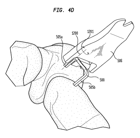
illustrated in Figure 4D (with arrow 1201 showing the direction of twisting
and
axis 1200 showing the axis of twisting. Then, referring to Figure 4E, the
transfer
apparatus 506 may be twisted in the opposite direction (see arrow 1205 showing
the direction of twisting) about another axis 1203 substantially parallel to,
but not
CA 02755008 2011-09-15
WO 2010/107549 PCT/US2010/024728
collinear with, the axis 1202 of the first leg 505a to snap the first leg 505a
past
the detent 522 and out of the transfer apparatus to completely remove the
staple
from the transfer apparatus. At this point, the staple 500 can then be pushed
fully into the holes, as needed.
[0038] Alternately, with reference to Figure 4F, the transfer apparatus may be
twisted about an axis 1207 generally defined by the backspan 504 of the staple
as illustrated by arrow 1206 to snap both legs 505a, 505b out of the transfer
apparatus simultaneously. Then, the backspan (assuming no detent adjacent
the backspan) will simply fall out of the transfer apparatus. It should be
noted
however, that because the backspan of surgical shape memory staples typically
have a zigzag in them as seen in the Figures (to allow the backspan to also
achieve some compression during the transition from martensitic state to
austentitic state), if the portion 521 a of the channel in the transfer
apparatus that
accommodates the backspan is formed as a straight groove and with a width
reasonably close to the diameter of the staple, there may not be enough
clearance in that channel portion to permit releasing of the staple from the
transfer apparatus by twisting about the backspan. Specifically, the zigzag in
the
backspan 504 may hit the wall of the channel portion 521 a and prevent further
twisting before the staple can be twisted enough to cause the legs 505a, 505b
to
clear the detents 522. Since a reasonably tight fit of the backspan 504 in the
channel portion 521 a of the transfer apparatus 500 is desirable in order to
keep
the staple 500 from sliding in the transfer apparatus in the direction
parallel to the
legs 505a, 505b of the staple 500 when seated in the transfer apparatus 506,
channel portion 521 a may be shaped eccentrically to accommodate the zigzag
and to permit twisting of the staple about its backspan. Figure 5 illustrates
such
an embodiment. As can be seen, the portion of the channel 521 a' in the
transfer
apparatus 506' that accepts the backspan 504 of the staple has two portions
1301 and 1302 that cause that channel portion 521 a' to correspond generally
to
the zigzag shape of the backspan of the staple. As shown, the channel portion
521 a' can accommodate the backspan 504 of the staple even when the staple is
twisted a full 90 out of the transfer apparatus, as shown.
11
CA 02755008 2011-09-15
WO 2010/107549 PCT/US2010/024728
[0039] Figure 5 also illustrates another alternative feature of the transfer
apparatus. Particularly, in order to enhance the ability of the transfer
apparatus
500' to deform to allow the legs 505a, 505b of the staple 500 to snap past the
detents 522 as previously described, grooves 1306, 1307 are cut into the
material of the transfer apparatus 506' parallel to the channel portions 521
b,
521 c bearing the detents. This will allow more flex in the material portions
1308,
1309 adjacent these channel portions 521 b, 521 c. This feature may be
particularly desirable in connection with transfer apparatus for larger size
staples,
which transfer apparatus may be larger in size, and therefore inherently more
rigid.
[0040] The transfer apparatus also may be used to remove the staple from
the surgical site in cases where that is necessary. Again, the wedge formation
510 may be inserted between the backspan of the staple (or other proximal
portion of a shape memory article) and the bone (or other anatomical feature)
to
which the backspan is adjacent in order to force the backspan away from the
bone essentially as described above in connection with the use of the wedge
portion to pull the backspan away from the constraining device 503. Once the
wedge is inserted so as to push the backspan sufficiently away from the
surface,
the surgeon can simply pull the transfer apparatus 506 perpendicularly away
from the surface of the bone. If more force is necessary than can reasonably
be
applied via the transfer apparatus, then the surgeon may instead remove the
transfer apparatus and grasp the staple with a grasping tool to pull it out.
[0041] The transfer apparatus comes in contact with the anatomy at the
surgical site. Accordingly, it should be made of a biocompatible material,
preferably a plastic biocompatible material. The transfer apparatus can be
designed as a re-usable device or as a single use device. If it is to be
reused, it
should be fabricated from a material that can withstand repeated autoclaving
processes. Many such materials are well known in the medical arts.
[0042] Fig. 6 illustrates an alternative embodiment of the invention. In this
embodiment, the shape memory article 500 is packaged at the factory embedded
12
CA 02755008 2011-09-15
WO 2010/107549 PCT/US2010/024728
within both a constraining device 555 and a transfer apparatus 560 as shown in
Fig. 6. In this embodiment, there is no ramp on the transfer apparatus insofar
as
the staple backspan and the proximal portion of the legs are already embedded
in the groove of the transfer apparatus.
[0043] In another embodiment, the constraining device may be completely
eliminated. For instance, depending primarily on the size, shape, and shape
memory properties of the shape memory device as well as the size and shape of
the passage in the transfer apparatus relative to the shape memory device, the
transfer apparatus may sufficiently restrain the shape memory article so as to
completely eliminate the need for a separate constraining device to hold the
distal end of the shape memory article pre-surgically. Accordingly, the shape
memory article may simply be packaged without a constraining device
essentially
as shown in Fig. 4C, i.e., with the proximal end embedded in the transfer
apparatus and the distal end free.
[0044] Figs. 7A-7C illustrate another embodiment of the invention. This
embodiment is substantially similar to the embodiment described above in
connection with Figs. 2-3 insofar as the transfer apparatus includes a wedge
formation 910 and a groove 921 that conforms to the size and shape of the
backspan of the shape memory staple and the proximal portions of the legs of
the staple. However, rather than having one or more detents in the groove to
assure that the staple does not inadvertently fall out of the groove, this
transfer
apparatus includes a cover portion 950 that is slidable between an open
position,
in which it does not cover the opening of the groove 921 in the major surface
951
of the transfer apparatus (the position shown in Fig. 7A) and a closed
position, in
which it does at least partially cover the groove 921 (the position shown in
Fig.
7B). The cover 950 may be shaped, as shown, to provide a convenient thumb
rest for the surgeon when holding the transfer device with a staple in it.
[0045] In this embodiment, the transfer apparatus is delivered to the surgeon
with the cover 950 in the closed position, as shown in Figure 7A. The cover
would remain in this closed position throughout the entire surgical procedure
until
13
CA 02755008 2011-09-15
WO 2010/107549 PCT/US2010/024728
the time when the transfer apparatus is to be detached from the staple (e.g.,
after
the distal portions of the legs of the staple have been inserted into the
holes in
the anatomical feature in which it will be implanted). Then, the surgeon can
slide
the cover 950 back with his thumb and simply translate the transfer apparatus
in
the direction represented by arrow B in Fig. 7B, i.e., parallel to the major
surface
951, to disengage the transfer apparatus from the staple. An advantage of this
embodiment is that the detents may be eliminated so that the entire groove 921
is sized slightly larger than the diameter of the staple so that no force need
be
applied to the staple when removing the transfer apparatus from the staple
after
partial implantation.
[0046] The slidable cover 950 may be attached to the main body of the
transfer apparatus by any reasonable mechanism that would allow it to slide.
For
instance, in one embodiment illustrated in Figure 7C, a slot 955 is provided
in the
aforementioned major surface 951 and completely through to the opposing major
surface 922 of the transfer apparatus 906 and a corresponding pin 957 is
provided on the underside of the cover 950 to mate with the slot 955 and slide
in
the slot. The distal-most portion of the pin 957 may be enlarged to form a
button,
ball, T shaped extension or other form of flange 958 with a diameter larger
than
the width of the slot so that the flange 957 is trapped in the slot 955 to
hold the
cover 950 to the main portion of the transfer apparatus, but allow it to slide
in the
slot 955.
[0047] In the embodiment illustrated in Figures 7A-7C, the cover 950 covers
only the backspan portion of the groove 921. However, in other embodiments, it
can cover the entire groove, including the portions that hold the proximal
portions
of the legs of the shape memory staple. This might provide more support for
the
staple and, particularly, prevent it from rocking about an axis parallel to
the legs
of the staple during implantation.
[0048] In another embodiment, the features of the embodiment of Figure 5
allowing easier removal of the staple by providing grooves 1306, 1307 parallel
and adjacent the channel portions 521 b, 521 c that allow the material
portions
14
CA 02755008 2011-09-15
WO 2010/107549 PCT/US2010/024728
1308, 1309 that bear the detents 522 to flex more easily (see Figure 5) may be
combined with the cover feature of the embodiment of Figures 7A-7C. In fact,
in
yet another embodiment, the grooves 1306, 1307 may be reduced to nominal
size such that there is a very small gap or no actual gap between material
portions 1308, 1309 and middle material portion 1311. Instead, material
portion
1311 (or at least a substantial portion of it extending up to the front
surface) may
be integral with or attached to the cover so that it slides back with the
cover.
Thus, when the cover is in the closed position covering backspan channel
portion
521 a, the staple is held securely in the channel by detents 522 because
material
portions 1308, 1209 bearing the detents cannot move because they are blocked
by material portion 1311. However, when the cover is slid open to reveal the
backspan channel 521a, the material portion 1311 also slides back so that it
no
longer blocks material portions 1308, 1309. Material portions 1308, 1309 may
be
slidable medially once material portion 1311 is moved away. Alternately, they
may be flexible as described in connection with the embodiment of Figure 5. Of
course, in such an embodiment, material portion 1311 would need to be
specially
shaped and attached to the cover to provide clearance to slide back without
being blocked by the backspan of the staple held in the channel portion 521 a.
For instance, material portion 1311 could be attached to the cover via the
flange
958 adjacent the back surface 922 (as illustrated in the embodiment of Figure
7C) and material portion could be shallower in depth so as not to extend all
the
way to front surface 951 so as not to interfere with the staple. Furthermore,
another channel would need to be provided in the transfer apparatus into which
material portion 1311 would slide when the cover is opened.
[0049] Having thus described a few particular embodiments of the invention,
various alterations, modifications, and improvements will readily occur to
those
skilled in the art. Such alterations, modifications, and improvements as are
made
obvious by this disclosure are intended to be part of this description though
not
expressly stated herein, and are intended to be within the spirit and scope of
the
invention. Accordingly, the foregoing description is by way of example only,
and
CA 02755008 2011-09-15
WO 2010/107549 PCT/US2010/024728
not limiting. The invention is limited only as defined in the following claims
and
equivalents thereto.
16