Note: Descriptions are shown in the official language in which they were submitted.
CA 02755125 2016-06-07
COUNTERCURRENT TANGENTIAL CHROMATOGRAPHY METHODS, SYSTEMS, AND
APPARATUS
FIELD OF THE INVENTION
[0002] The present invention is generally related to chromatography. More
specifically, this invention relates to a
method, system, and apparatus of tangential chromatography using
countercurrent flow to facilitate separation of the
desired product and enhance efficiency of the entire chromatography process.
BACKGROUND OF THE INVENTION
[0003] There has been a significant and sustained growth in new drug
production featuring monoclonal antibodies
and other proteins, approximately 15-20% annually. This growth is due to
expanding drug pipelines, as well as more
efficient cell lines and bioreactor growth optimizations. The annual bio-
production costs are currently estimated at
$2.6 billion. One of the most significant investments a drug manufacturer has
to make is process chromatography
(approximately 30% or $850 million annually).
[0004] Chromatography is an integral part of drug production; its purpose in
the biotechnology industry is to
purify the product proteins from contaminating species. The industry has
started to recognize that the efficiency of
The chromatography steps which are used to purify the product proteins are no
longer keeping up with production
demands. There are multiple reasons for this:
[0005] First, no significant improvements have been made to the column
chromatography process in the past 30
years ¨ most of the work in the industry has been focused on new resin
development A notable exception is
membrane chromatography which was recently adopted by the industry.
[0006] Second, upstream technology has improved tremendously in the same time
period ¨ the bioreactors are
larger- (up to 20,000 liters), and the titers are much higher (up to 15 g/L
compared with 1-2 g/L five years ago). As a
1
CA 02755125 2011-09-09
WO 2010/107677 PCT/US2010/027266
result of longer fermentation times, there are generally more impurities in
the bioreactor effluent solution. All of the
above reasons result in a much heavier load for the downstream purification.
[0007] Third, column chromatography has inherent physical limitations. Columns
larger than 2 meter in diameter
do not scale up. The largest columns in the market are 2 meter diameter and 40
cm bed height. They fit 1,250 L of
resin. Assuming a binding capacity of 30 g/L of resin (common Protein A resin
capacity for monoclonal antibodies),
a single cycle can bind 38 kg. A 20,000 L bioreactor with an output of 10 g/L
would produce a load of 200 kg. This
means that the biggest column in the market would have to run at least 6 full
cycles to process a single batch. The
operation can take up to 24 hrs and can result in a significant bottleneck for
the manufacturing process.
[0008] Finally, in the present marketplace, disposability in the manufacturing
process is gaining popularity.
Disposable process steps save labor, do not require cleaning validation and
are easier to run for the manufacturing
personnel. Strides have been made in most downstream processes to have
disposable systems. These are ¨
bioreactors (up to 2,000 L volume Xcellerex Corp.), microfiltration (KleenPak
TFF technology from Pall Corp.),
depth filtration (POD, Millipore Corp.), sterile filtration (all major
manufacturers), tangential flow filtration (all
major manufacturers) and membrane chromatography (Mustang, Pall Corp.,
Sartobind, and Sartorius Corp.). The
column chromatography technology because of its inherent limitation cannot be
a part of the disposable trend.
Therefore, it is currently impossible to have a completely disposable
downstream process ¨ a purification train must
include a chromatography step which cannot be disposable.
[0009] Therefore, it was recognized by the present inventor that a
breakthrough in the state of the art would
include solutions to the above problems. It was recognized that the industry
needs 1) larger scale of operation; 2)
faster processing time; 3) disposability; 4) reduction of media/resin
expenses; and 5) a reduction of capital
equipment investment.
[0010] It is against this background that various embodiments of the present
invention were developed.
BRIEF SUMMARY OF THE INVENTION
[0011] Therefore, one embodiment of the present invention is a scalable,
reliable and disposable technology that
utilizes a principle of recycling to significantly increase process
efficiency, increase the scale of operation, and
decrease resin costs.
2
CA 02755125 2011-09-09
WO 2010/107677 PCT/US2010/027266
[0012] In the present invention, the chromatography column is replaced by a
module that consists of two or more
interconnected tangential flow filters and static mixers. The chromatography
resin flows through this module in a
single pass, while similar operations to a regular chromatographic process are
performed on the resin (binding,
washing, elution, regeneration, and equilibration). The buffers for these
operations are pumped into the module in a
countercurrent direction to the flow of resin, and permeate solutions from
later stages are recycled back into
previous stages. This creates concentration gradients in the permeate
solutions of the tangential flow filters in the
countercurrent direction to resin flow, thus saving buffer volume and
increasing process efficiency. The permeate
solutions from binding, washing, equilibration and regeneration operations are
put to waste. The permeate solution
from the elution operation is the purified product stream which is collected
in a separate product tank.
[0013] Accordingly, one embodiment of the present invention is a module 100
for countercurrent tangential
chromatography (see Figure 1) comprising a first input port (101) for
receiving an input solution; a first mixer (102)
for mixing the input solution with a recycled solution from a second input
port (103) to produce a first mixer output;
a stage I filter (104) for concentrating the first mixer output to produce
stage I retentate, wherein stage I permeate
solution exits the module from the stage I filter via a first output port
(105); a second mixer (106) for mixing the
stage I retentate from the stage I filter (104) and an optional buffer
solution from a second input port (107); and a
stage II filter (108) for concentrating an output from the second mixer (106)
to produce stage II retentate which exits
the module from the stage II filter via a second output port (110), wherein
stage II permeate solution exits the
module from the stage II filter via a third output port (109).
[0014] Another embodiment of the present invention is the module described
above wherein the input solution
comprises resin and unpurified product solution.
[0015] Another embodiment of the present invention is the module described
above wherein the stage I permeate
solution is waste.
[0016] Another embodiment of the present invention is the module described
above wherein the stage I permeate
solution is product.
[0017] Another embodiment of the present invention is the module described
above wherein the second mixer
receives clean buffer solution.
[0018] Another embodiment of the present invention is the module described
above wherein the second mixer
does not receive clean buffer solution.
3
. . > CA 02755125 2012-02-23
[00191 Another embodiment of the present invention is the module described
above wherein the third output port
(109) is connected via a pump (112) and a three-way valve (111) to the second
input port (103). (See Figure 1.)
[0020] Another embodiment of the present invention is the module described
above wherein the three-way valve
(111) sends an output from the third output port (109) either to waste or
product (113), or to the second input port
(103). (See Figure 1.)
100211 Another embodiment of the present invention is the module described
above wherein the stage I filter and the
stage II filter are tangential flow filters.
[0022] Yet another embodiment of the present invention is a system (300) for
countercurrent tangential
chromatography (see Figure 3) comprising a module (100) for countercurrent
tangential chromatography; a first resin
tank (302) for storing clean resin connected to a first input port (101) of
the module; an input tank (304) for storing
input solution connected to the first input port (101); a pump (112) and a
three-way valve (111) interconnecting a
second input port (103) with a third output port (109) of the module; a second
resin tank (325) for storing resin
connected to a second output port (110) of the module via a pump (323) and the
three-way valve (317), and connected
to the first input port (101) of the module via a pump (313); a product tank
(309) for capturing product solution
connected via a three-way valve (307) and a pump (308) to the first output
port (105) of the module; and one or more
buffer tanks (316, 318, 320, 322) for storing buffer solution connected to the
third input port (107) of the module via a
pump (314), wherein the first resin tank (302) is connected via 3-way valve
(317) to second resin tank (325) and pump
(323).
[0023] Another embodiment of the present invention is the system described
above further comprising an additional
countercurrent tangential chromatography stage comprising a third mixer (530)
and a third filter (532), for increasing
efficiency of the system. (See Figure 5.)
10023a] Accordingly, in one aspect the present invention resides in a module,
comprising: a first input port for
receiving an input solution; a first mixer for mixing the input solution with
a recycled solution from a second input port
to produce a first mixed output; a stage I filter for concentrating the first
mixed output to produce stage I retentate,
4
CA 02755125 2012-02-23
wherein stage I permeate exits the module from the stage I filter via a first
output port; a second mixer for
mixing the stage I retentate from the stage I filter and an optional buffer
solution from a third input port to
produce a second mixed output; and a stage II filter in series with the stage
I filter for concentrating the second
mixed output to produce stage II retentate which exits the module from the
stage II filter via a second output
port, wherein stage II permeate exits the module from the stage II filter via
a third output port, wherein the input
solution from input port flows through the stage I filter and the stage II
filter in a single pass, and recycled
solution from the third output port flows countercurrent to the input solution
into the second input port.
[0023131 In another aspect the present invention resides in a system for
continuous, single-pass countercurrent
tangential chromatography having multiple single-pass modules, comprising: a
single-pass binding step module
for binding product from an unpurified product solution with a resin slurry; a
single-pass washing step module
for washing impurities from the resin slurry; a single-pass elution step
module for eluting an output of the
washing stage module as purified product solution; and a single-pass
regeneration step module for regenerating
the resin slurry, wherein each module comprises an interconnected tangential
flow filter and a static mixer,
wherein the resin slurry flows in a continuous, single-pass through each of
the single-pass modules, and wherein
one or more of the single-pass modules comprise two or more stages with
permeate flow directed
countercurrent to resin slurry flow within that single-pass module.
100241
Other embodiments of the present invention include the methods corresponding
to the systems above,
the systems constructed from the modules described above, and the methods of
operation of the systems and
modules described above. Other features and advantages of the various
embodiments of the present invention
will be apparent from the following more particular description of embodiments
of the invention as illustrated in
the accompanying drawings.
4a
CA 02755125 2011-09-09
WO 2010/107677 PCT/US2010/027266
BRIEF DESCRIPTION OF THE DRAWINGS
[0025] Figure 1 shows a module for countercurrent tangential chromatography
according to one embodiment of
the present invention.
[0026] Figure 2A shows direction of flow in the module during binding mode,
while Figure 2B shows direction
of flow in the module during elution, washing, equilibration, and regeneration
modes.
[0027] Figure 3 shows a block diagram of a countercurrent tangential
chromatography system operating in batch
mode according to one embodiment of the present invention.
[0028] Figure 4 shows another block diagram of the countercurrent tangential
chromatography system of Figure 3.
[0029] Figure 5 shows a block diagram of another countercurrent tangential
chromatography system according to
another embodiment of the present invention.
[0030] Figure 6 shows a block diagram of another countercurrent tangential
chromatography system operating in
continuous mode, according to yet another embodiment of the present invention.
[0031] Figures 7A, 7B, and 7C show a flowchart of a process of countercurrent
tangential chromatography
operating in batch mode, according to yet another embodiment of the present
invention.
[0032] Figure 8 shows a flowchart of a process of countercurrent tangential
chromatography operating in
continuous mode, according to yet another embodiment of the present invention.
[0033] Figure 9 shows results of a mathematical model of a two-stage
countercurrent tangential chromatography
system according to the principles of the present invention, showing a ratio
of buffer to resin flow-rates (gamma) vs.
percent yield for various sieving coefficients.
[0034] Figure 10 shows results of a mathematical model of a three-stage
countercurrent tangential
chromatography system according to the principles of the present invention,
showing a ratio of buffer to resin flow-
rates (gamma) vs. percent yield for various sieving coefficients.
DETAILED DESCRIPTION OF THE INVENTION
[0035] Definitions: The following terms of art shall have the below ascribed
meanings throughout this
Specification.
[0036] Binding mode is a stage of operation during which resin and unpurified
product form a reversible complex.
CA 02755125 2011-09-09
WO 2010/107677 PCT/US2010/027266
[0037] Washing mode is a stage of operation during which resin with bound
product is washed with a washing
buffer to rid the resin of impurities.
[0038] Elution mode is a stage of operation during which the complex of resin
and the product is reversed and the
purified product is collected.
[0039] Regeneration mode is a stage of operation during which the resin is
cleaned for the purpose of reuse or for
later cycles.
[0040] Equilibration mode is a stage of operation during which the system is
equilibrated in a neutral buffer.
[0041] As stated in the Summary of the Invention section, in the present
invention, the chromatography column is
replaced by a module that consists of two or more interconnected tangential
flow filters and static mixers. The
chromatography resin flows through this module in a single pass, while similar
operations to a regular
chromatographic process are performed on the resin (binding, washing, elution,
regeneration, and equilibration). The
buffers for these operations are pumped into the module in a countercurrent
direction to the flow of resin, and
permeate solutions from later stages are recycled back into previous stages.
This creates concentration gradients in
the permeate solutions of the tangential flow filters in the countercurrent
direction to resin flow, thus saving buffer
volume and increasing process efficiency. The permeate solutions from binding,
washing, equilibration and
regeneration operations are put to waste. The permeate solution from the
elution operation is the purified product
stream which is collected in a separate product tank.
[0042] Accordingly, Figure 1 shows a block diagram of a module 100 for
countercurrent tangential
chromatography (inside the dotted line). Input solution enters at port 101,
and the input solution and any input from
port 103 (none during binding mode) are mixed inside static mixer 102. The
output from the static mixer 102 enters
a tangential flow filter 104, from which the permeate exits the module at port
105. The retentate from tangential
flow filter 104 is fed into static mixer 106, which may receive pure buffer at
port 107. The output from static mixer
106 is fed into a tangential flow filter 108, from which permeate is pumped
via pump 112 out of the module at port
109. Three-way valve 111 is utilized to direct flow either to waste 113 or to
port 103. The retentate from tangential
flow filter 108 exits the module at port 110. During washing, elution,
equilibration and regeneration, three-way
valve 111 directs the flow to port 103, where it mixes with input 101 in
static mixer 102. During binding, three-way
valve 111 directs the flow to waste 113.
6
CA 02755125 2011-09-09
WO 2010/107677 PCT/US2010/027266
[0043] Figure 2A shows direction of flow in module 100 of figure 1 during
binding mode. Note the single-pass
nature of the flow, and the fact that no flow enters at port 103 and port 107.
The mixture of resin and non-purified
product solution enter at the left through port 101 (through mixer 102), flows
through filter 104 (with permeate
exiting as waste at port 105), flows through mixer 106, flows through filter
108 (with permeate exiting as waste at
port 109 via pump 112 and three-way valve 111), and exits the module at the
right through port 110.
[0044] Figure 2B shows direction of flow in module 100 during elution,
washing, regeneration, and equilibration
modes. Note the single-pass nature of the flow, and the fact that flow is
recycled in a countercurrent direction from
port 109 to port 103 via pump 112 and three-way valve 111. Note how in this
configuration, clean buffer solution
enters at port 107, and recycled buffer solution enters at port 103. Note also
the countercurrent nature of the flow,
where the solution being processed flows left-to-right as in Figure 2A, while
recycled buffer solution flows from
right-to-left via pump 112 and three-way-valve 111, in a direction that is
"counter-current" to the left-to-right flow
of the solution being processed.
[0045] Figure 3 shows a block diagram of a countercurrent tangential
chromatography system 300 operating in
batch mode according to another embodiment of the present invention. Module
100 operates in the same way as
shown and described in relation to Figure 1. Input port 101 of module 100 is
connected to pumps 303, 305 and 313.
Pump 303 pumps resin from first resin tank 302. Pump 313 pumps resin from
second resin tank 325. Pump 305
pumps unpurified product solution from input tank 304. Port 103 of module 100
is connected via three-way valve
111 and pump 112 to port 109 of module 100, as shown in Figure 1. Waste exits
the system at 113. Output from port
105 is connected to pump 306, which is connected to a three-way valve 307.
Three-way valve 307 is connected to
product tank 309 and waste 308. Port 107 receives input into module 100 via
pump 314, which is connected to
equilibration tank 316, washing tank 318, elution tank 320 and regeneration
tank 322 via valves 315, 317, 319 and
321. Output from port 110 is pumped via pump 323 and three-way valve 317 to
the first resin tank 302 and a second
resin tank 325.
[0046] The system in Figure 3 is designed to treat the resin using a batch-
mode operation. The resin is sequentially
treated by different chromatographic processes (binding, washing, elution,
regeneration, and equilibration) as it
cycles from the first resin tank 302 to the second resin tank 325 and vice
versa. For example, during the first stage
(binding), resin passes from tank 302 to tank 325 from left to right through
module 100 via pump 303. During the
next stage (washing) resin passes from tank 325 to tank 302 from left to right
through module 100 via pump 313.
7
CA 02755125 2011-09-09
WO 2010/107677 PCT/US2010/027266
The other stages (elution, regeneration, and equilibration) alternate tanks in
a similar manner. The countercurrent
operation during washing, elution, regeneration, and equilibration allows
greater efficiency and buffer conservation.
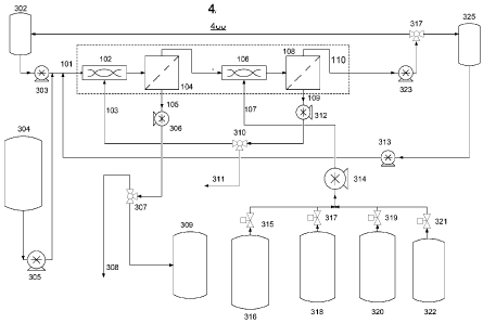
[0047] Figure 4 shows a block diagram 400 of the countercurrent tangential
chromatography system shown in
Figure 3, with the internal structure of module 100 shown. Figure 4 is
identical to Figure 3 with the exception that
the internals of module 100 are shown as in Figure 1.
[0048] Figure 5 shows a block diagram 500 of another countercurrent tangential
chromatography system 500
according another embodiment of the present invention. This embodiment is
similar to Figures 3 and 4, except for
addition of an additional (third) stage of countercurrent filtration, made up
of mixer 530, filter 532, pump 533, and
three-way valve 531, interconnected as shown in Figure 5. Waste exits at 536.
The embodiment shown in Figure 5
operates in a manner analogous to the system shown in Figures 3 and 4, with
the exception that flow passes through
a third stage, which increases process efficiency and decreases buffer
utilization, but introduces some complexity
into the design. Mathematical modeling described below shows that using more
than three stages produces no
appreciable improvement in process efficiency while introducing substantial
complexity. Hence, more than three
stages, while possible according to the principles of the present invention
and within the scope of the present
invention, are not described further.
[0049] Figure 6 shows a block diagram 600 of another countercurrent tangential
chromatography system operating
in continuous mode, according to yet another embodiment of the present
invention. Modules 610 ("binding stage"),
620 ("washing stage"), 630 ("elution stage"), 640 ("regeneration stage") and
650 ("equilibration stage") operate in
an analogous manner to the operation of module 100 shown in Figures 1, 2A and
2B. The thick black line on
modules 620, 630, 640 and 650 represent a connection of a third output port
(109) and a second input port (103) via
pump (112) and three-way valve (111) on each module shown. These pumps and
three-way valves are not shown in
Figure 6 for clarity, but they are present in each module 620, 630, 640 and
650 as shown in Figure 1. Note that
module 610 ("binding stage") does not have its third output port (609) nor its
second input port (607)
interconnected, since in this module both port 609 and port 607 go to waste.
[0050] Binding stage module 610 is connected at port 605 via pump 604 to non-
purified product tank 602, via
pump 606 to resin tank 608, and via three-way valve 658 and pump 657 to
equilibration buffer tank 656. Ports 607
and 609 on module 610 go to waste.
8
CA 02755125 2011-09-09
WO 2010/107677 PCT/US2010/027266
[0051] Washing stage module 620 is connected at port 613 via pump 612 to an
output port 611 of the binding
stage module 610. Port 621 goes to waste via pump 622. Washing buffer enters
at port 627 via pump 626 from
washing buffer tank 624.
[0052] Elution stage module 630 is connected at port 625 via pump 624 to
output port 623 of washing stage
module 620. Elution buffer enters at port 637 via pump 639 from elution buffer
tank 638. Purified product exits
module 630 at port 627 via pump 636 into product storage tank 632.
[0053] Regeneration module 640 is connected at port 635 via pump 634 to output
port 633 of module 630. Waste
exits at port 643 via pump 646. Regeneration buffer enters at port 645 via
pump 641 from regeneration buffer tank
642.
[0054] Equilibration module 650 is connected at port 649 via pump 648 to
output port 647 of regeneration module
640. Resin is pumped out of port 651 via pump 652 into the resin storage tank
608. Waste is pumped from module
650 at port 661 via pump 653. Equilibration buffer enters at port 659 via the
three-way valve 658 and the pump 657
from the equilibration buffer tank 656.
[0055] Accordingly, unlike the system of Figure 3, which is designed to treat
the resin/product in alternating
batch-mode, with resin alternating between the first and the second resin
tanks, the system of Figure 6 is designed to
treat the resin/product in a single continuous pass, with resin flowing
continuously from the resin tank 608, through
modules 610, 620, 630, 640, and 650, and returning to resin tank 608. The
continuous nature of the system shown in
Figure 6 allows a fixed amount of resin to be used for processing an
essentially unlimited amount of unpurified
product, subject only to the lifetime of the resin.
[0056] Figures 7A, 7B, and 7C show a flowchart of a process 700 of
countercurrent tangential chromatography
operating in batch mode, according to yet another embodiment of the present
invention. Process 700 begins at step
702. The system is flushed with equilibration buffer, as shown in step 704. In
step 706, the binding stage is started
(emphasis in bold). Resin and non-purified product is pumped into the system
at appropriate flow rates, as shown in
step 708. The permeate solutions are discarded from all stages as waste during
the binding stage only, as shown in
step 710. The resin is collected with bound product as shown in step 712.
[0057] In step 714, the washing stage is started (emphasis in bold). The
system is flushed with washing buffer, as
shown in step 716. The countercurrent permeate is recycled and utilized during
the washing stage to improve
process efficiency and conserve buffer solution according to the principles of
the present invention, as shown in step
9
CA 02755125 2011-09-09
WO 2010/107677 PCT/US2010/027266
718. Resin is pumped with bound product back into the first stage of the
system, where it mixes with the recycled
wash buffer, as shown in step 724. The washed resin with bound product is
collected in the first resin tank, while
permeate solution is discarded as waste, as shown in step 726.
[0058] In step 728, the elusion stage is started (emphasis in bold). The
system is flushed with elution buffer, as
shown in step 730. The countercurrent permeate is recycled and reused during
the elution stage in order to improve
process efficiency and to conserve buffer solution, as shown in step 732.
Resin bound with product is pumped back
into the first stage of the system, where it mixes with the recycled elusion
solution, as shown in step 734.
[0059] In step 736, permeate solution from the first stage is collected as
product solution (emphasis in bold).
Resin is collected in the second resin tank, as shown in step 738.
[0060] In step 740, the regeneration stage is started (emphasis in bold). The
system is flushed with regeneration
solution, as shown in step 742. The countercurrent permeate is recycled and
reused during the regeneration stage, in
order to improve process efficiency and to conserve buffer solution, as shown
in step 744. The resin is pumped into
the first stage, where it mixes with the recycled regeneration solution, as
shown in step 746. The permeate solution
is discarded as waste, as shown in step 748.
[0061] In step 750, the resin is collected in the first resin tank (emphasis
in bold), hence completing the cycle and
allowing the reuse of resin.
[0062] Finally, the equilibration process using equilibration buffer may be
repeated if more cycles are required, as
shown in step 752. Alternatively, equilibration process may be performed with
storage solution if the resin requires
storage, as shown in step 752. The process 700 ends in step 754.
[0063] Figure 8 shows a flowchart of a process 800 of countercurrent
tangential chromatography operating in
continuous mode, according to yet another embodiment of the present invention.
Process 800 begins in step 802.
The binding stage (Module 610 of Figure 6) is flushed with equilibration
buffer, as shown in step 804. The washing
stage (Module 620 of Figure 6) is flushed with washing buffer, as shown in
step 806. The elution stage (Module
630 of Figure 6) is flushed with elution buffer, as shown in step 808. The
regeneration stage (Module 640 of Figure
6) is flushed with regeneration buffer, as shown in step 810. The
equilibration stage (Module 650 of Figure 6) is
flushed with equilibration buffer, as shown in step 812. Resin and non-
purified product are fed at the appropriate
flow rates into the first stage of the system (Module 610 of Figure 6), as
shown in step 814. All buffer solutions are
fed into the appropriate stages at appropriate flow rates, as shown in step
816. The purified product is collected
CA 02755125 2011-09-09
WO 2010/107677 PCT/US2010/027266
from the elution stage (Module 630 of Figure 6), while all other buffer
solutions are discarded to waste, as shown in
step 818. The entire system is kept running continuously until the non-
purified product solution is completely
consumed, as shown in step 820. The process 800 ends in step 822.
MODELING
[0064] Product recovery is one of the most important cost drivers in
chromatography. This is because the protein
molecules are of extremely high value. A capture chromatography process should
have a recovery of at least 90%.
Therefore, it was decided to model the product recovery stage of the present
invention (the elution stage).
[0065] The following assumptions were made in this model:
[0066] 1. The tangential flow (TFF) membranes in the module are able to
process the slurry of resin and elution
buffer at appropriate conversion factors (upwards of 80%).
[0067] 2. The kinetics of desorption of the product molecule from the resin is
fast.
[0068] 3. The sieving coefficient of the TFF membrane is constant through
ought the process.
[0069] 4. The system is "dead-space" free.
[0070] The impact on the percent yield (% recovery) of the following variables
are explored in this model:
[0071] 1. "Gamma (7)" is the ratio of elution buffer flow-rate to resin buffer
flow rate, and governs the dilution
of the product, buffer usage, and washing efficiency. This variable can be
controlled by the operator.
[0072] 2. "s" is the sieving coefficient of the TFF membrane for the
product molecule. s equals the product
concentration in the permeate divided by the product concentration in the
retentate. This is an inherent property of
the membrane and cannot be changed by the operator.
[0073] 3. "N" is the number of stages; the present model explores a two-
stage and a three-stage system in
operation. As the number of stages increases, the washing efficiency and
product recovery increases, with all other
variables are held constant. However, more stages increase the complexity and
cost of the system.
[0074] Model equations were derived by using material balances and solving for
% yield. It became convenient to
introduce a new variable a =
[0075] Equation 1 shows the percent-yield for a two-stage system as a function
of a:
(1) %Yield = (1 1 )*100%
(1+a + a2)
11
CA 02755125 2011-09-09
WO 2010/107677 PCT/US2010/027266
[0076] Equation 2 shows the percent-yield for a three-stage system as a
function of a:
(2) %Yield = (1 1 ) *100%
(1 +a + a 2 +a 3 )
[0077] Figures 9 and 10 show the results of this model; gamma (7) is the
independent variable, and percent (%)
yield is the dependent variable. Percent yield curves are generated for
specific sieving coefficients for both models
(s = 0.5, 0.7, 0.8, 1.0).
[0078] Figure 9 shows the results for a two-stage countercurrent tangential
chromatography system showing the
ratio of buffer to resin flow-rates (gamma) vs. percent yield for sieving
coefficients s = 0.5, 0.7, 0.8, 1Ø
[0079] Figure 10 shows the results for a three-stage countercurrent tangential
chromatography system showing the
ratio of buffer to resin flow-rates (gamma) vs. percent yield for sieving
coefficients s = 0.5, 0.7, 0.8, 1Ø
[0080] The results of the model show that greater than 95% yield can be
achieved by both the two-stage and the
three-stage systems. Sieving coefficients for these processes are expected to
be within a range of [0.8 ¨ 1.01 because
the membranes used in this system would be microporous and would therefore be
expected to pass the product
molecule relatively freely. The two-stage system would need a higher buffer to
feed ratio (7) than the three-stage
system to achieve the same percent (%) yield. Therefore, the recommended
operating gamma (7) for a two-stage
system is 4 to 6, and for a three-stage system the recommended operating gamma
(7) is 3 to 4.
[0081] A modeling example is described here of protein A capture of 20,000 L
bioreactor harvest, 5 g/L IgG
concentration, in a three-stage countercurrent tangential chromatography
system operating in batch mode, as shown
in Figure 5. This example is illustrative of one of many modes of operation of
the present invention.
[0082] This modeling example makes the following assumptions:
[0083] 1. Residence time = 0.5 min (hypothetical "small" protein A bead)
[0084] 2. Resin capacity = 30 g/L
[0085] 3. General Electric hollow fibers are used as the TFF membrane. The
areas and hold up volumes are
used from existing large scale General Electric modules.
[0086] 4. Flux = 100 LMH
[0087] 5. An 80% conversion factor is assumed in the TFF filters.
12
CA 02755125 2011-09-09
WO 2010/107677 PCT/US2010/027266
Table 1. Modeling results
Volume 20000 L Binding stage time
0.175 hrs
Product conc. 5 g/L
Total product 100 kg Wash Volume 4 Resin Volumes (R\/)
1200 L
Total Membrane area 300 m2 VVashin stage Time
0.120 his
# of stages 3
Washing dilution factor 4 Elution Volume 4 Resin Volumes
(R\/) 1200 L
Resin Volume 300 L Elution stage Time
0.12 his
Resin Capacity 30 g/L
Regeneration Buffer volume ( 4 RV) optional 1200
L
Flux 100 LMH VVash Time
0.120 his
One cycle processes 9 kg MAB
One cycle Volume 1800 L Equilibration Buffer volume (4
R\/) 1200
VVash Time
0.120 his
Residence time 0.5 min
Static mixer volume 100 L
Total Flow 200 Umin
Resin Flow rate 28.6 Umin Total Cycle time
0.66 hrs
Feed Flow rate 171.4 Umin # of cycles 12
Feed Flux 34.3 LMH Total Processing Time
7.9 hrs
[0088] The results of this model show the following:
[0089] 1. 20,000 L of unpurified product can be processed with 300 L of resin
which represents a factor of 4
decrease from conventional column chromatography.
[0090] 2. The operation can be performed in a single 8-hr shift.
[0091] 3. Number of cycles can be decreased by increasing resin volume.
[0092] 4. Efficiency and process time could be increased by increasing flux.
[0093] The inventor recognizes numerous and substantial advantages of the
present invention to the downstream
purification process, including:
[0094] 1. Current technology could be readily adapted to this process because
existing components are readily
available in the market. Namely, the tangential flow filters (cassettes,
hollow fibers and ceramic membranes) and
chromatography resins are readily available. It might be advantageous to
develop a new line of resins specifically
designed for this invention by using smaller beads than in conventional column
chromatography. This would nullify
mass transfer limitations, increase dynamic binding capacity, and make the
process more efficient.
[0095] 2. Tangential chromatography systems according to the principles of
this invention may be scaled as
large as necessary, similarly to any tangential flow system. This is not the
case with conventional column
chromatography ¨ the largest scalable columns in the market are currently
limited to 2 meters in diameter.
13
CA 02755125 2011-09-09
WO 2010/107677 PCT/US2010/027266
[0096] 3. Continuous-mode countercurrent tangential chromatography can be
designed as shown in Figure 6.
In general, continuous processes are more efficient and require a smaller
system size.
[0097] 4. There is potential to run this system in a completely disposable
manner. This is because much smaller
amounts of resin are needed for this operation than in column chromatography
(this would be true for cheaper resin
kinds such as ion exchange resins). Additionally, the tangential flow filters
at smaller scales could be used on a
disposable basis as well.
[0098] 5. The use of resin could be an order of magnitude lower than in
conventional chromatography, causing
significant cost savings by as much as 80%.
[0099] Therefore, the present inventor recognizes numerous applications of the
present invention to the $850+
million/year process chromatography market.
[00100] U.S. Patent No. 4,780,210 to Jen-Chang Hsia entitled "Tangential
flow affinity ultra-filtration"
describes a process for trypsin purification. More particularly, it relates to
a process of biochemical purification
which combines the processing techniques of affinity chromatography and
tangential ultra-filtration, and is capable
of being operated on a continuous flow or semi-continuous-flow basis, for use
in the purification (or separation) of
molecules of biological interest. The process of the present invention is
verifiably different because of the
countercurrent and single-pass nature, along with various other improvements.
The process described in U.S. Patent
No. 4,780,210 is not suitable for the biotech market.
[00101] U.S. Patent Nos. 6,139,746 and 6,214,221 to Henry B. Kopf
(hereinafter "the Kopf patents") describe
a process and apparatus for purifying a target substance from a source liquid
using a cross-filter element system.
The Kopf patents, as shown in Figures 2, 5 and 6, describe a system and
process for contacting a source liquid with
resin, allowing the resin to bind desired fraction of target substances, re-
circulating the resin in a cross-flow filter
system and ultimately recovering the target substance from the resin. Counter-
current tangential chromatography
(CTC) shows at least three distinctions from these patents: First, CTC is a
process and system based on continuous
and steady-state treatment of the materials (single pass); second, CTC
utilizes a counter-current recycling loop for
recycling buffer to the start of the process; and third, CTC uses static
mixing or static mixers for combining the resin
and source liquid, as opposed to stirred or complete flow mixing. These are
each discussed in turn below:
[00102] Continuous and steady-state processing: CTC allows a one-pass,
continuous and steady-state
resolution for resin and target product as it flows through the CTC system.
The resin processing and product
14
CA 02755125 2011-09-09
WO 2010/107677 PCT/US2010/027266
separation is highly efficient and providing more efficient yields than non-
continuous/non-steady state
systems/processes. The Kopf patents rely upon batch-wise and unsteady state
processing of the resin. The Kopf
system also has a specific focus on small (a few m) non-porous particles, but
the CTC system is sufficiently
flexible to employ a wide range of particle types.
[00103] Counter-current recycling loop: CTC describes a counter-current
flow between buffer and
resin/permeate. The counter-current flow creates a concentration gradient in
the permeate solutions of the tangential
flow filters in the counter-current direction to resin flow. This counter-
current flow saves buffer volume and
increases process efficiency. Modeling results shown above provide support for
these claims.
[00104] Static mixing: CTC uses static mixing or static mixers. Inclusion
of static mixers is significant in both
performance and cost improvements. The Kopf system is most appropriately
compared with the batch
implementation of the CTC system; as noted previously, the Kopf structure is
not amenable to continuous operation.
Although the separator in both cases is a membrane filtration device, the
contacting units differ: an agitated vessel in
Kopf and a static mixer in CTC. The static mixer has the advantage of allowing
good control of the contacting time,
whereas the agitated vessel yields a wide distribution of contacting times. In
addition, the holdup in the agitated
vessel is higher; the corresponding holdup in the CTC units is smaller.
Consequently, the capital cost of the Kopf
system is higher, but that also locks in the scale of the operation, which is
more easily changed for the CTC system,
which has functional units that are relatively inexpensive and indeed may be
treated as disposable.
INDUSTRIAL APPLICABILITY AND ADVANTAGES OF THE PRESENT INVENTION
[00105] The countercurrent tangential chromatography (CTC) method provides
a means for obtaining some of
the benefits of chromatographic purification within a framework free of the
normal packed column format. The
scheme employs contactor ¨ separator functional units that allow better
control of contacting times than do
alternative approaches based on agitated vessels. Such units can be especially
effective in allowing matching of
flow rates suitable for optimal binding efficiency. Subsequent steps (wash,
elution, regeneration, equilibration) are
performed in the same format. The structure overall appears best suited for
capture steps, and offers the advantages
of reduced capital costs, facile scale-up and use of disposable components.
[00106] Chromatography as operated in the preparative bind¨elute mode is
inherently a batch process, the
design of which must balance the advantages of rapid mass transfer against the
disadvantages of rapid momentum
transfer (manifested as a high pressure drop). This trade-off results in
limitations on flow rate, particle size and
CA 02755125 2011-09-09
WO 2010/107677 PCT/US2010/027266
column length, while practical issues related to such factors as flow
distribution limit column diameter. The CTC
framework allows several of these issues to be circumvented, as well as
introducing some additional factors:
[00107] Although the basic CTC contacting unit is amenable to batch
operation, fully continuous operation is
also possible via replication of the contacting unit. For pharmaceutical
operations, continuous operation is important
due to the advantage of a low-volume chromatography system to process a large
volume of feed.
[00108] The basic CTC contacting unit is a modern equivalent of an
equilibrium stage contactor ¨ separator
unit, although the use of static mixers and hollow fiber or similar separation
units considerably reduces dispersion
(back-mixing), which allows better control of contacting times. Using 2-3 of
these units in series allows relatively
complete mass transfer even with fairly short contacting times.
[00109] Replacement of packed-bed contacting with a well-mixed system
eliminates the main constraint
against reduction of particle size, namely column pressure drop. Thus smaller
particle sizes can be used, allowing
for faster mass transfer, especially during loading.
[00110] Another advantage of loading in a well-mixed system is the ability
to control the volume balance of
resin flow and feed flow. With the dilute feeds and relatively high capacities
typical for these kinds of processes,
loading a packed column to near full capacity requires feeding many column
volumes at low flow rates, whereas the
use of a resin suspension allows the flow ratio to be maintained directly.
[00111] Eliminating large packed columns removes a major capital
investment, to be replaced by smaller,
cheaper and potentially disposable CTC functional units. Both static mixers
and hollow fiber modules are available
in a variety of sizes, making scale-up possible.
EXPERIMENTAL RESULTS
[00112] Materials & Methods: All the chromatographic experiments were
carried out with strong anion
exchange resin, Macro-Prep 25Q which was donated by Bio-Rad Laboratories
(Hercules, CA). The nominal
particle size of this resin is 25 micrometer with nominal pore size as 725
Angstrom. MidiCros0 hollow fiber
modules (Product Number ¨ X32E-901-02N) were donated by Spectrum Laboratories
(Rancho Dominguez, CA).
Each hollow fiber module housed ten polyethersulfone fibers with 0.2 micron
pore size and was approximately 64
cm long with 1 mm inner diameter giving total surface area of 200 cm2 per
module. Static mixtures are 11.25 inch
long with 0.4 inch inner diameter and were purchased from Koflo Corp (Cary,
IL). Bovine serum albumin (A7906)
and myoglobin (M0630) from horse skeletal muscle were purchased from Sigma-
Aldrich (St. Louis, MO). The
16
CA 02755125 2011-09-09
WO 2010/107677 PCT/US2010/027266
phosphate buffer was prepared by dissolving appropriate quantities of sodium
phosphate dibasic heptahydrate (J.T.
Baker) and potassium phosphate monobasic crystal (J.T. Baker) in deionized
water obtained from NANOpure
Diamond water purification system (Barnstead Thermolyne Corp) with a
resistivity greater than 18 Me-cm. The
pH of the solution was measured using a Thermo Orion model 420Aplus pH meter
and adjusted by addition of 0.1
M HC1 or NaOH as required. High ionic strength elution buffer was prepared by
dissolving appropriate quantity of
sodium chloride (J.T. Baker) in 20 mM ionic strength phosphate buffer at pH 7.
[00113] Analysis: BSA concentrations in the samples collected from binding
kinetics experiments were
determined from absorbance at 280 nm using a spectrophotometer. A calibration
curve was created for BSA by
serial dilution in order to convert the absorbance reading into BSA
concentrations. Size exclusion chromatography
was used to quantitatively analyze the samples collected during two-stage CTC
process for the presence of BSA and
myoglobin. An Agilent 1100 HPLC system with Superdex 200, 10/300 gel
permeation column from GE Healthcare
(Uppasala, Sweden) was used for the size exclusion chromatography which gave
an excellent baseline resolution
between BSA and myoglobin peaks. 0.15 M NaC1 in 50 mM phosphate buffer at pH 7
was used as mobile phase at
flow rate of 0.4 mL/min. 100 microliter samples were injected over a period of
30 s and the effluent from Superdex
200 column was monitored on Agilent 1200 series UV-Vis detector at 205 nm for
protein concentrations. An
appropriate calibration curve was used to calculate the concentrations of BSA
and myoglobin from the peak areas.
[00114] Two-stage CTC Experiment: A pump drives concentrated slurry from
the feed tank to 1st static
mixture where it gets mixed with the permeate stream from 2nd hollow fiber
module in appropriate ratio. The 1st
static mixer provides good mixing between the concentrated fresh resin slurry
and the permeate stream from 2nd
hollow fiber unit along with the sufficient residence time. The well-mixed
diluted slurry from 1st static mixture
enters the 1st hollow fiber unit and gets divided in to two streams:
concentrated resin slurry as retentate stream and
resin-free permeate stream. The permeate stream from the 1st hollow fiber
module is collected in the tank as either
product or waste. The retentate stream of 1st hollow fiber module enters the
2nd static mixture where it again gets
mixed with fresh buffer (in case of washing or elution step) or feed protein
solution (in case of binding step) in an
appropriate ratio. The diluted slurry from 2nd static mixture enters the 2nd
hollow fiber module and gets divided in
to two streams: the retentate stream which consists of concentrated resin
slurry and resin-free permeate stream. The
permeate from the 2nd hollow fiber module is directed towards the 1st static
mixture while the retentate is collected
17
CA 02755125 2016-06-07
'
in a separate tank for further processing. Hollow fiber membrane modules were
used in constant flux mode using a
two-channel permeate pump and pressure drops along the membrane as well as
across the membrane were
monitored using pressure sensors.
[00115] Results: Complete separation of the binary protein system
(BSA/myoglobin) has been achieved with
BSA purity of 99.5% and yield of 93%. Theoretical modeling and experimental
results were shown to agree within
5%.
[00116] Accordingly, while the methods disclosed herein have been
described and shown with reference to
particular operations performed in a particular order, it will be understood
that these operations may be combined,
sub-divided, or re-ordered to form equivalent methods without departing from
the teachings of the present invention.
Accordingly, unless specifically indicated herein, the order and grouping of
the operations is not a limitation of the
present invention.
[00117] Finally, while the invention has been particularly shown
and described with reference to particular
embodiments thereof, it will be understood by those skilled in the art that
various other changes in the form and details
may be made without departing from the scope of the invention.
18