Note: Descriptions are shown in the official language in which they were submitted.
CA 02755231 2011-10-14
Attorney Docket No. 25.0571
Inventors: VARKEY et al.
WIRELINE CABLES NOT REQUIRING SEASONING
BACKGROUND
[0001] The statements in this section merely provide background information
related to
the present disclosure and may not constitute prior art.
[0002] The invention is related in general to well site equipment such as
wireline
surface equipment, wireline cables and the like.
[0003] A process of removing the plastic stretch from a cable by allowing
contra-helical
armor layers on the cable to seat properly is known as "seasoning" of the
cable. Cables
are often "seasoned" in order to minimize damage to the cable and provide
accurate
depth measurements.
[0004] A seasoning process can include a "pre-stress" operation accomplished
by
subjecting a cable in an ends-fixed condition to high stresses at elevated
temperatures.
By performing the pre-stress operation, plastic stretch is partially removed
from the
cable, which allows the armor to arrange itself on the cable core. A pre-
stressed cable
has to be further "broken-in" during the first couple of visits to the well
site. The process
of "breaking-in" is done by running cable into a well, while carrying a heavy
tool string
which is free to rotate. Running in speed during the seasoning process has to
be much
slower compared to that for the "seasoned" cable. Cables armored with
galvanized steel
armor undergo seasoning quite well, which is attributed to the properties of
the
galvanized steel armor package. On the other hand, alloy cables having smooth
non-
corrosive armor do not season.
[0005] Specifically, alloy armor has smooth, almost slick, properties which
inhibit
corrosion and allow the armor to slide around much more freely. Therefore,
"seasoning"
cannot be applied to alloy cables, creating a number of operational issues.
Certain alloy
cables are highly torque imbalanced which manifests itself through excessive
rotation
downhole and resulting in a stretch on the alloy armor cable that is higher
than a
galvanized steel armored cable. This torque imbalance may also create an issue
with
accurate depth measurement. Accordingly, the probability of bird caging of the
alloy
armor cable is higher than with galvanized steel armored cabled.
1
CA 02755231 2011-10-14
Attorney Docket No. 25.0571
Inventors: VARKEY et al.
[0006] Taking this into account, well site operations with alloy cable are
much more
time consuming, as running in and pulling out of the hole has to be done at
speeds
much slower than that of galvanized armored cable.
[0007] It remains desirable to provide improvements in wireline cables and/or
downhole
assemblies.
SUMMARY
[0008] The present disclosure provides a cable that does not require seasoning
or pre-
stressing operations. Designs provided below are equally applicable to any
cable
configuration (mono, coax, triad, quad, hepta or any other) having various
armor layers
(e.g. steel, alloy, and the like).
[0009] In an embodiment, a cable comprises: an electrically conductive cable
core for
transmitting electrical power and data, such as telemetric data or the like;
an insulative
and/or protective jacket or layer circumferentially disposed around the core;
an inner
armor wire layer including a plurality of armor wires disposed around the
insulative/protective layer, wherein at least one of the armor wires of the
inner armor
wire layer is bonded to the insulative layer; and an outer armor wire layer
including a
plurality of armor wires disposed around the inner armor wire layer.
[0010] In an embodiment, a cable comprises: an electrically conductive cable
core for
transmitting electrical power; a insulative layer circumferentially disposed
around the
core; an inner armor wire layer including a plurality of armor wires disposed
around the
insulative/protective layer, wherein at least one of the armor wires of the
inner armor
wire layer includes a coating bonded to the insulative/protective layer to
substantially fix
a position of the at least one of the armor wires of the inner armor wire
layer relative to
the insulative/protective layer; and an outer armor wire layer including a
plurality of
armor wires disposed around the inner armor wire layer.
[0011] Methods for construction of a wireline cable are also disclosed.
[0012] In an embodiment, a method comprises the steps of: providing an
electrically
conductive cable core for transmitting electrical power and data; disposing a
insulative/protective layer circumferentially around the core; providing an
inner armor
wire layer including a plurality of armor wires, wherein at least one of the
armor wires of
the inner armor wire layer includes a coating; heating the coating of the at
least one of
2
CA 02755231 2011-10-14
Attorney Docket No. 25.0571
Inventors: VARKEY et al.
the armor wires of the inner armor wire layer to soften the coating; disposing
the inner
armor wire layer around the insulative layer, wherein the coating of the at
least one of
the armor wires of the inner armor wire layer is bonded to the
insulative!protective layer
to substantially fix a position of the at least one of the armor wires of the
inner armor
wire layer relative to the insulative/protective layer; and disposing an outer
armor wire
layer around the inner armor wire layer, the outer armor wire layer including
a plurality
of armor wires.
BRIEF DESCRIPTION OF THE DRAWINGS
[0013] These and other features and advantages of the present disclosure will
be
better understood by reference to the following detailed description when
considered in
conjunction with the accompanying drawings wherein:
[0014] FIG. 1 is a radial cross-sectional view of a first embodiment of a
cable ;
[0015] FIG. 2 is a radial cross-sectional view of a second embodiment of a
cable ;
[0016] FIG. 3 is a radial cross-sectional view of a third embodiment of a
cable ;
[0017] FIG. 4 is a radial cross-sectional view of a fourth embodiment of a
cable;
[0018] FIG. 5 is a partially exploded radial cross-sectional view of a portion
of a fifth
embodiment of a cable ;
[0019] FIG. 6 is a radial cross-sectional view of the cable of FIG. 5;
[0020] FIG. 7 is a radial cross-sectional view of the cable of FIG. 5,
including an outer
layer of armor wires;
[0021] FIG. 8 is a partially exploded radial cross-sectional view of a portion
of a sixth
embodiment of a cable ;
[0022] FIG. 9 is a radial cross-sectional view of the cable of FIG. 8;
[0023] FIG. 10 is a radial cross-sectional view of the cable of FIG. 8,
including an outer
layer of armor wires;
[0024] FIG. 11 is a partially exploded radial cross-sectional view of a
portion of a
seventh embodiment of a cable;
3
CA 02755231 2011-10-14
Attorney Docket No. 25.0571
Inventors: VARKEY et at.
[0025] FIG. 12 is a radial cross-sectional view of the cable of FIG. 11;
(0026] FIG. 13 is a radial cross-sectional view of the cable of FIG. 11,
including an
outer layer of armor wires;
[0027] FIG. 14 is a partially exploded radial cross-sectional view of a
portion of an eight
embodiment of a cable ;
[0028] FIG. 15 is a radial cross-sectional view of the cable of FIG. 14;
[0029] FIG. 16 is a partially exploded radial cross-sectional view of the
cable of FIG. 14,
including an outer layer of armor wires; and
[0030] FIG. 17 is a radial cross-sectional view of the cable of FIG. 16.
DETAILED DESCRIPTION OF THE INVENTION
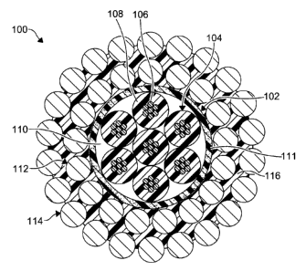
[0031] Referring to FIG. 1, there is illustrated a cable 100 according to a
first
embodiment of the present disclosure. As shown, the cable 100 includes a core
102
having a plurality of conductors 104. As a non-limiting example, each of the
conductors
104 is formed from a plurality of conductive strands 106 disposed adjacent
each other
with an insulator 108 disposed therearound. As a further non-limiting example,
the core
102 includes seven distinctly insulated conductors 104 disposed in a hepta-
cable
configuration. However, any number of conductors 104 can be used in any
configuration, as desired. In certain embodiments an interstitial void 110
formed
between adjacent insulators 108 is filled with a semi-conductive (or non-
conductive)
filler (e.g. filler strands, polymer insulator filler).
[0032] A layer of insulative or protective material 111 (e.g. polymer) is
circumferentially
disposed around the core 102. As a non-limiting example, the insulative
material is a
short-fiber-reinforced polymer extruded over the core 102. However, other
materials and
methods of insulating the core can be used. The material 111 may be an
insulative
material, a protective material, or both an insulative material and protective
material.
[0033] The core 102 and the insulative layer 111 are surrounded by an inner
layer of
alloy armor wires 112 (e.g. high modulus steel strength members) that are
cabled at a
pre-determined lay angle. In certain embodiments, the inner layer 112 is at
least
partially embedded in the layer of insulative material 111. The inner layer
112 is
surrounded by an outer layer of alloy armor wires 114. As a non-limiting
example the
4
CA 02755231 2011-10-14
Attorney Docket No. 25.0571
Inventors: VARKEY et al.
layers 112, 114 are contra helically wound with each other. As a non-limiting
example,
an interstitial void created in the layers 112, 114 (e.g. between adjacent
ones of the
armor wires of the inner layer 112 and the outer layer 114) is filled with a
polymer as
part of a jacket 116. In the embodiment shown, the jacket 116 encapsulates the
inner
layer 112 and covers at least a portion of the outer layer 114. It is
understood that the
jacket 116 can cover any portion of the layers 112, 114.
[0034] In operation, the cable 100 is coupled to a tractor in a configuration
known in the
art. The cable 100 is introduced into the wellbore, without the requirement of
seasoning
or pre-stressing operations. It is understood that various tool strings can be
coupled to
the cable 100 and/or the tractor to perform various well service operations
known in the
art.
[0035] FIG. 2 illustrates a torque balanced cable 100' for tractor or other
toolstring
operations according to a second embodiment of the present disclosure similar
to the
cable 100, except as described below. As shown, the core 102 is surrounded by
an
inner layer of alloy armor wires 112' (e.g. high modulus steel strength
members) that
are cabled at a pre-determined lay angle. In certain embodiments, the inner
layer 112' is
at least partially embedded in the layer of insulative material 111. The inner
layer 112' is
surrounded by an outer layer of alloy armor wires 114'. As a non-limiting
example the
layers 112', 114' are contra helically wound with each other. As shown, a
coverage or
size of the outer layer 114' relative to the inner layer 112' is configured to
substantially
match a torque generated by the inner layer 112'. As a non-limiting example
the
coverage of the outer layer 114' over the inner layer is between about 50% to
about
90%. It is understood that a reduction in the coverage allows the cable 100'
to achieve
torque balance and advantageously minimizes a weight of the cable 100'. As a
further
non-limiting example, layers 112', 114' of the cable 100' are configured
similar to the
cable described in U.S. Pat. Appl. Pub. No. 2009/0283295.
[0036] In operation, the cable 100' is coupled to a tractor in a configuration
known in the
art. The cable 100' is introduced into the wellbore, wherein a torque on the
cable 100' is
substantially balanced. It is understood that various tool strings can be
coupled to the
cable 100' and the tractor or other toolstring to perform various well service
operations
known in the art.
[0037] FIG.3 illustrates a cable 200 according to a third embodiment of the
present
disclosure similar to the cable 100, except as described below. As shown, the
cable 200
includes a core 202 having a plurality of conductors 204. As a non-limiting
example,
CA 02755231 2011-10-14
Attorney Docket No. 25.0571
Inventors: VARKEY et al.
each of the conductors 204 is formed from a plurality of conductive strands
206
disposed adjacent each other with an insulator 208 disposed therearound. As a
further
non-limiting example, the core 202 includes seven distinctly insulated
conductors 204
disposed in a hepta-cable configuration. However, any number of conductors 204
can
be used in any configuration, as desired. In certain embodiments an
interstitial void 210
formed between adjacent insulators 208 is filled with a semi-conductive (or
non-
conductive) filler (e.g. filler strands, polymer insulator filler, gunk).
[0038] A layer of insulative material 211 (e.g. polymer and/or composite) is
circumferentially disposed around the core 202. As a non-limiting example, the
insulative material is a short-fiber-reinforced polymer extruded over the core
202.
However, other materials and methods of insulating the core can be used. The
material
211 may be an insulative material, a protective material, or both an
insulative material
and protective material.
[0039] The core 202 and the insulative layer 211 are surrounded by an inner
layer of
alloy armor wires 212 (steel strength members) that are cabled at a pre-
determined lay
angle. In certain embodiments, the inner layer 212 is at least partially
embedded in the
layer of insulative material 211. The inner layer 212 is surrounded by an
outer layer of
alloy armor wires 214. As a non-limiting example the layers 212, 214 are
contra helically
wound with each other. As a non-limiting example, an interstitial void created
in the
layers 212, 214 (e.g. between adjacent ones of the armor wires of the inner
layer 212
and the outer layer 214) is filled with a polymer as part of a jacket 216. In
the
embodiment shown, the jacket 216 encapsulates the inner layer 212 and covers
at least
a portion of the outer layer 214. It is understood that the jacket 216 can
cover any
portion of the layers 212, 214.
[0040] As a non-limiting example, each of the alloy armor wires of the layers
212, 214
includes an alloy (or steel) core wire 212A, 214A coated with a tie layer
212B, 214B
and an outer polymer coating 212C, 214C to bond to the polymeric jacket 216.
As a
further non-limiting example, each of the tie layers 212B, 214B can be formed
from
brass, zinc, aluminum, or other suitable material to bond the alloy core wire
212A, 214A
to the polymer coating 212C, 214C. Therefore, the polymeric jacket 216 becomes
a
composite in which the layers 212, 214 are embedded in a continuous matrix of
polymer
from the core 202 to an outer surface of the jacket 216.
[0041] In operation, the cable 200 is coupled to a tractor or another
toolstring in a
configuration known in the art. The cable 200 is introduced into the wellbore,
without the
6
CA 02755231 2011-10-14
Attorney Docket No. 25.0571
Inventors: VARKEY et al.
requirement of seasoning or pre-stressing operations. It is understood that
various tool
strings can be coupled to the cable 200 and the tractor to perform various
well service
operations known in the art. It is further understood that the bonding of the
layers 212,
214 to the jacket 216 minimizes stripping of the jacket 216.
[0042] FIG. 4 illustrates a torque balanced cable 200' according to a fourth
embodiment
of the present disclosure similar to the cable 200, except as described below.
As shown,
the core 202 is surrounded by an inner layer of alloy armor wires 212' (e.g.
high
modulus steel strength members) that are cabled at a pre-determined lay angle.
In
certain embodiments, the inner layer 212' is at least partially embedded in
the layer of
insulative material 211. The inner layer 212' is surrounded by an outer layer
of alloy
armor wires 214'. As a non-limiting example the layers 212', 214' are contra
helically
wound with each other. As shown, a coverage or size of the outer layer 214'
relative to
the inner layer 212' is configured to substantially match a torque generated
by the inner
layer 212'. As a non-limiting example the coverage of the outer layer 214'
over the inner
layer is between about 50% to about 90%. It is understood that a reduction in
the
coverage allows the cable 200' to achieve torque balance and advantageously
minimizes a weight of the cable 200'. As a further non-limiting example,
layers 212',
214' of the cable 200' are configured similar to the cable described in U.S.
Pat. Appl.
Pub. No. 2009/0283295.
[0043] In operation, the cable 200' is coupled to a tractor or other
toolstring in a
configuration known in the art. The cable 200' is introduced into the
wellbore, wherein a
torque on the cable 200' is substantially balanced. It is understood that
various tool
strings including a tractor can be coupled to the cable 200' and the tractor
to perform
various well service operations known in the art.
[0044] FIGS. 5-7 illustrate a cable 300 for tractor operations according to a
fifth
embodiment of the present disclosure similar to the cable 100, except as
described
below. As shown, the cable 300 includes a core 302 having a plurality of
conductors
304. As a non-limiting example, each of the conductors 304 is formed from a
plurality of
conductive strands 306 disposed adjacent each other with an insulator 308
disposed
therearound. As a further non-limiting example, the core 302 includes seven
distinctly
insulated conductors 304 disposed in a hepta-cable configuration. However, any
number of conductors 304 can be used in any configuration, as desired. In
certain
embodiments interstitial voids 310 formed between adjacent insulators 308 are
filled
7
CA 02755231 2011-10-14
Attorney Docket No. 25.0571
Inventors: VARKEY et al.
with a semi-conductive (or non-conductive) filler (e.g. filler strands,
polymer insulator
filler, or gunk).
[0045] A layer of insulative material 311 (e.g. polymer) is circumferentially
disposed
around the core 302. As a non-limiting example, the insulative material is a
short-fiber-
reinforced polymer extruded over the core 302. However, other materials and
methods
of insulating the core can be used. The material 311 may be an insulative
material, a
protective material, or both an insulative material and proactive material.
[0046] The core 302 and the insulative layer 311 are surrounded by an inner
layer of
alloy or steel armor wires 312 (e.g. high modulus steel strength members) that
are
cabled at a pre-determined lay angle. A coated one 312' of the armor wires of
the inner
layer 312 includes a polymer coating 313 that bonds to an armor wire core
312A' of the
coated armor wire 312'. As the inner layer of alloy armor wires 312 is cabled
together
over the insulative material 311 covering the core 302, a heat source (for
example,
infrared heating) is applied to soften the polymer coating 313 on the coated
armor wire
312' of the inner layer 312. It is understood that various sources of thermal
energy can
be used such as infrared heaters emitting short, medium or long infrared
waves,
ultrasonic waves, microwaves, lasers, other suitable electromagnetic waves,
conventional heating, induction heating, and the like. As the inner layer 312
seats
against the core 302, the polymer coating 313 of the coated armor wire 312'
bonds to
the layer of insulative material 311 and deforms to fill interstitial spaces
between the
coated armor wire 312' and the adjacent armor wires. The inner layer 312 is
surrounded
by an outer layer of an alloy or steel armor wires 314, further locking the
inner layer 312
into place and minimizing any stretching of the cable 302.
[0047] In operation, the cable 300 is coupled to a tractor in a configuration
known in the
art. The cable 300 is introduced into the wellbore, without the requirement of
seasoning
or pre-stressing operations. It is understood that various tool strings can be
coupled to
the cable 300 and the tractor to perform various well service operations known
in the
art. It is further understood that layers 312, 314 maybe be formed from
galvanized
improved plow steel (GIPS) or alloy armor wire strength members.
[0048] FIGS. 8-10 illustrate a cable 400 for tractor operations according to a
fifth
embodiment of the present disclosure similar to the cable 300, except as
described
below. As shown, the cable 400 includes a core 402 having a plurality of
conductors
404. As a non-limiting example, each of the conductors 404 is formed from a
plurality of
conductive strands 406 disposed adjacent each other with an insulator 408
disposed
8
CA 02755231 2011-10-14
Attorney Docket No. 25.0571
Inventors: VARKEY et al.
therearound. As a further non-limiting example, the core 402 includes seven
distinctly
insulated conductors 404 disposed in a hepta-cable configuration. However, any
number of conductors 404 can be used in any configuration, as desired. In
certain
embodiments an interstitial void 410 formed between adjacent insulators 408 is
filled
with a semi-conductive (or non-conductive) filler (e.g. filler strands,
polymer insulator
filler).
[0049] A layer of insulative material 411 (e.g. polymer) is circumferentially
disposed
around the core 402. As a non-limiting example, the insulative material is a
short-fiber-
reinforced polymer extruded over the core 402. However, other materials and
methods
of insulating the core can be used. The material 411 may be an insulative
material, a
protective material, or both an insulative material and proactive material.
[0050] The core 402 is surrounded by an inner layer of alloy armor wires 412
(e.g. high
modulus steel strength members) that are cabled at a pre-determined lay angle.
A
plurality of coated ones 412' of the armor wires of the inner layer 412
include a polymer
coating 413 that bonds to an armor wire core 412A' of the coated armor wires
412'. As
the inner layer of alloy armor wires 412 is cabled together over the
insulative material
411 covering the core 402, a heat source is applied to slightly soften the
polymer
coating 413 on the coated armor wire 412' of the inner layer 412. As the inner
layer 412
seats against the core 402, the polymer coating 413 of each of the coated
armor wires
412' bonds to the layer of insulative material 411 and deforms to fill
interstitial spaces
between the coated armor wire 412' and the adjacent armor wires of the inner
layer
412. The inner layer 412 is surrounded by an outer layer of alloy armor wires
414,
further locking the inner layer 412 into place and minimizing any stretching
of the cable
402.
[0051] In operation, the cable 400 is coupled to a tractor in a configuration
known in the
art. The cable 400 is introduced into the wellbore, without the requirement of
seasoning
or pre-stressing operations. It is understood that various tool strings can be
coupled to
the cable 400 and the tractor to perform various well service operations known
in the
art. It is further understood that layers 412, 414 maybe be formed from
Galvanized
Improved Plow Steel(GIPS), steel, other metals or alloy armor wire strength
members.
[0052] FIGS. 11-13 illustrate a cable 500 for tractor operations according to
a fifth
embodiment of the present disclosure similar to the cable 300, except as
described
below. As shown, the cable 500 includes a core 502 having a plurality of
conductors
504. As a non-limiting example, each of the conductors 504 is formed from a
plurality of
9
CA 02755231 2011-10-14
Attorney Docket No. 25.0571
Inventors: VARKEY et al.
conductive strands 506 disposed adjacent each other with an insulator 508
disposed
therearound. As a further non-limiting example, the core 502 includes seven
distinctly
insulated conductors 504 disposed in a hepta-cable configuration. However, any
number of conductors 504 can be used in any configuration, as desired. In
certain
embodiments interstitial voids 510 formed between adjacent insulators 508 is
filled with
a semi-conductive (or non-conductive) filler (e.g. filler strands, polymer
insulator filler,
gunk).
[0053] A layer of insulative material 511 (e.g. polymer) is circumferentially
disposed
around the core 502. As a non-limiting example, the insulative material is a
short-fiber-
reinforced polymer extruded over the core 502. However, other materials and
methods
of insulating and/or protecting the core can be used. The material 511 may be
an
insulative material, a protective material, or both an insulative material and
protective
material.
[0054] The core 502 and the insulative material 511 are surrounded by an inner
layer of
alloy or steel armor wires 512 (e.g. high modulus steel strength members) that
are
cabled at a pre-determined lay angle. Each of the armor wires of the inner
layer 512
include a polymer coating 513 that bonds to an armor wire core 51 2A of the
armor wires
of the inner layer 512 As the inner layer of alloy or steel armor wires 512 is
cabled
together over the insulative material 511 covering the core 502, a heat source
is applied
to soften the polymer coating 513 on each of the armor wires of the inner
layer 512. As
the inner layer 512 seats against the core 502, the polymer coating 513 of
each of the
armor wires bonds to the layer of insulative material 511 and deforms to fill
interstitial
spaces between the adjacent armor wires of the inner layer 512. The inner
layer 512 is
surrounded by an outer layer of alloy or steel armor wires 514, further
locking the inner
layer 512 into place and minimizing any stretching of the cable 502.
[0055] In operation, the cable 500 is coupled to a tractor in a configuration
known in the
art. The cable 500 is introduced into the wellbore, without the requirement of
seasoning
or pre-stressing operations. It is understood that various tool strings can be
coupled to
the cable 500 and including the tractor to perform various well service
operations known
in the art. It is further understood that layers 512, 514 maybe be formed from
GIPS,
steel, other metals or alloy armor wire strength members.
[0056] FIGS. 14-17 illustrate a cable 600 for tractor operations according to
a fifth
embodiment of the present disclosure similar to the cable 300, except as
described
below. As shown, the cable 600 includes a core 602 having a plurality of
conductors
CA 02755231 2011-10-14
Attorney Docket No. 25.0571
Inventors: VARKEY et al.
604. As a non-limiting example, each of the conductors 604 is formed from a
plurality of
conductive strands 606 disposed adjacent each other with an insulator 608
disposed
therearound. As a further non-limiting example, the core 602 includes seven
distinctly
insulated conductors 604 disposed in a hepta-cable configuration. However, any
number of conductors 604 can be used in any configuration, as desired. In
certain
embodiments an interstitial void or voids 610 formed between adjacent
insulators 608 is
filled with a semi-conductive (or non-conductive) filler (e.g. filler strands,
polymer
insulator filler, gunk or combinations thereof).
[0057] A layer of insulative material 611 (e.g. polymer) is circumferentially
disposed
around the core 602. As a non-limiting example, the insulative or protective
material is a
short-fiber-reinforced polymer extruded over the core 602. However, other
materials and
methods of insulating the core can be used. The material 611 may be an
insulative
material, a protective material, or both an insulative material and protective
material.
[0058] The core 602 and the insulative material 611 are surrounded by an inner
layer of
alloy armor wires 612 (e.g. high modulus steel strength members) that are
cabled at a
pre-determined lay angle. Each of the armor wires of the inner layer 612
include a
polymer coating 613 that bonds to an armor wire core 612A of the armor wires
of the
inner layer 612. As the inner layer of alloy armor wires 612 is cabled
together over the
insulative material 611 covering the core 602, a heat source is applied to
slightly soften
the polymer coating 613 on each of the armor wires of the inner layer 612. As
the inner
layer 612 seats against the core 602, the polymer coating 613 of each of the
armor
wires bonds to the layer of insulative material 611 and deforms to fill
interstitial spaces
between the adjacent armor wires of the inner layer 612.
[0059] The inner layer 612 is surrounded by an outer layer of alloy or steel
armor wires
614 (e.g. high modulus steel strength members) that are cabled at a pre-
determined lay
angle. Each of the armor wires of the outer layer 614 includes a polymer
coating 615
that bonds to an armor wire core 614A of the armor wires of the inner layer
614. As the
outer layer of alloy or steel armor wires 614 is cabled together over the
inner layer 612,
a heat source is applied to soften the polymer coating 613 on each of the
armor wires of
the outer layer 614. As the outer layer 614 seats against the inner layer 612,
the
polymer coating 615 of each of the armor wires in the outer layer 614 bonds to
the
polymer coating 613 of each of the armor wires of the inner layer 612 and
deforms to fill
interstitial spaces between the adjacent armor wires of each of the layers
612, 614. It is
understood that any number of the armor wires of the layers 612, 614 can be
coated
11
CA 02755231 2011-10-14
Attorney Docket No. 25.0571
Inventors: VARKEY et al.
with the polymer coating 613, 615. However, favorable results have been found
with all
of the armor wires of the layers 612, 614 including the polymer coating 613,
615 to
ensure a more circular cable profile with no high spots.
[0060] In operation, the cable 600 is coupled to a tractor or other toolstring
in a
configuration known in the art. The cable 600 is introduced into the wellbore,
without the
requirement of seasoning or pre-stressing operations. It is understood that
the fixed
armor wires of the layers 612, 614 are bonded to each other and to the core
602 to
secure each other in place around the core 602 and minimize any stretching of
the
cable 600. It is further understood that layers 612, 614 maybe be formed from
GIPS or
alloy armor wire strength members.
[0061] The innovative designs described above provide ways to produce steel
and alloy
cables that do not require seasoning or pre-stressing operations. Designs
provided
below are equally applicable to any cable configuration (mono, coax, triad,
quad, hepta
or other). The following are at least some the benefits of the embodiments
disclosed
herein: Fully seasoned cable; Reduced torque and therefore rotation; due to
filled
interstitial voids, A reduced amount of grease to seal on the cable at the
well head is
needed; No pressure loss due to fluid migration through interties between the
armor;
Increased speed for run in and out of the hole is possible; Reduced chance of
bird
caging or knotting; Lower stretch; Stiffer cable; and, as a consequence,
faster and
simpler rig up/down.
[0062] The polymeric materials useful in the cables of the invention may
include, by
non-limiting example, thermoplastics (such as PEEK, PEK, PEKK, PPS,
Polypropylene
[PP], TPX, or EPC), polyamides (such as Nylon-6, Nylon-11, Nylon-12, or Nylon-
66),
fluoropolymers (such as Perfluoro Ethylene Propylene [FEP], [PFA], Tefzel,
etc.), and
combination of the same.
[0063] In cases where it is desirable for bonding to be facilitated between
materials that
would not otherwise bond to a substrate, the described polymers may be amended
with
one of several adhesion promoters, such as: unsaturated anhydrides, (mainly
maleic-
anhydride, or 5-norbornene-2, 3-dicarboxylic anhydride), carboxylic acid,
acrylic acid, or
silanes. Trade names of commercially available, amended polyolefin with these
adhesion promoters include: ADMER from Mitsui Chemical; Fusabond , Bynel
from
DuPont; Polybond from Chemtura; TPXTM from Mitsui Chemical; and amended TPX
(4-methylpentene-1 based, crystalline polyolefin) in combination with the
above
adhesion promoters.
12
CA 02755231 2011-10-14
Attorney Docket No. 25.0571
Inventors: VARKEY et al.
[0064] Modified fluoropolymers containing adhesion promoters may also be used
where
needed to facilitate bonding between materials that would not otherwise bond,
such as:
Tefzel from DuPont Fluoropolymers; Modified ETFE resin which is designed to
promote adhesion between polyamide and fluoropolymer; Neoflon TM-Modified
fluoropolymer from Daikin America, Inc., which is designed to promote adhesion
between polyamide and fluoropolymer; ETFE (Ethylene tetrafluoroethylene) from
Daikin
America, Inc.; and EFEP (ethylene-fluorinated ethylene propylene) from Daikin
America,
Inc.
[0065] The strength members useful in the cables of the invention may include,
by non-
limiting example, alloy armor wire (MP35N, HC265 etc), regular steel wire,
galvanized
steel wire, GIPS wire, pearlitic steels, regular steel wire coated with brass,
copper or
zinc, followed by a bonded layer of polymer, fiber strength members, stranded
armor
wires, copper-clad steel, aluminum-clad steel, anodized aluminum-clad steel,
titanium-
clad steel, carpenter alloy 20Mo6HS, ZAPP alloy 27-7MO, GD31 Mo, austeniic
stainless
steel, galvanized carbon steel, copper, titanium clad copper, and any other
metals,
composites or alloys. As a further non-limiting example several "types" of
strength
members may be used, including: allay or steel armor; alloy or steel armor
wires as is or
coated with brass, zinc or aluminum as a tie layer, then polymer; and stranded
fiber
strength members consisting of bundled filaments of steel, copper or carbon
fiber in
matrices of polymer, copper, zinc, aluminum, etc.
[0066] The particular embodiments disclosed above are illustrative, as the
embodiments may be modified and practiced in different but equivalent manners
apparent to those skilled in the art having the benefit of the teachings
herein.
Furthermore, no limitations are intended to the details of construction or
design herein
shown, other than as described in the claims below. It is therefore evident
that the
particular embodiments disclosed above may be altered or modified and all such
variations are considered within the scope and spirit of the invention. In
particular, every
range of values (of the form, "from about a to about b," or, equivalently,
"from
approximately a to b," or, equivalently, "from approximately a-b") disclosed
herein is to
be understood as referring to the power set (the set of all subsets) of the
respective
range of values. Accordingly, the protection sought herein is as set forth in
the claims
below.
[0067] The preceding description has been presented with reference to
presently
disclosed embodiments of the invention. Persons skilled in the art and
technology to
13
CA 02755231 2011-10-14
Attorney Docket No. 25.0571
Inventors: VARKEY et at.
which this invention pertains will appreciate that alterations and changes in
the
described structures and methods of operation can be practiced without
meaningfully
departing from the principle, and scope of this invention. Accordingly, the
foregoing
description should not be read as pertaining to the precise structures
described and
shown in the accompanying drawings, but rather should be read as consistent
with and
as support for the following claims, which are to have their fullest and
fairest scope.
14