Note: Descriptions are shown in the official language in which they were submitted.
CA 02755504 2011-09-14
WO 2010/107992 PCTIUS2010/027798
-1-
COSMETIC BRUSHES
BACKGROUND OF THE INVENTION
[00011 The application of makeup requires the even distribution of cosmetics.
To
obtain a natural-looking application, while achieving the desired enhanced
appearance
of the wearer's eyes, cheek or face, the cosmetics are often applied using a
variety of
cosmetic brushes or applicators, each having a specific cosmetic application.
Makeup
can also be used to camouflage or hide certain undesired colors, blemishes,
birthmarks, scars, or disfigurations on the face.
[0002] Cosmetics are often applied to the face by a brush or other applicator.
Cosmetic brushes comprise a variety of sizes and shapes, wherein each brush is
designed for a specific application or area of the face. One type of brush
used is a
"half.-moon" brush, which is flat in shape, with a head of parallel bristles
typically an
inch to an inch and a half (25 to 40 mm) wide and a quarter of an inch (6 mm)
or less
thick. The name "half-moon" arises because the tip edge of the head maybe
convex,
giving the head a D shape. The handle is typically rectangular, and similar in
size to
the head, though for practical reasons rather thicker.
[0003] Although convenient for applying a dusting of powder to a large area of
the
face, the "half-moon" brush is not compact in shape, and thus not easy to
store.
[0004] Thus, it is apparent that there has been, prior to the present
invention, an
unfulfilled need for an improved cosmetic brush.
SUMMARY OF THE INVENTION
[0005] An object of one embodiment of the present invention is to provide
cosmetic brushes that combine the broad, thin head of a half-moon brush with a
compact shape for storage.
[0006] An object of one embodiment of the present invention is to provide a
brush
comprising two parts, each having a flat head and a flat handle. The handle of
each
part has a wide major face and a narrow side face. The two parts can be placed
together in a first configuration with the two narrow side faces abutting and
the heads
parallel and side by side to form a single wide, flat head. The two parts can
be placed
CA 02755504 2011-09-14
WO 2010/107992 PCT/US2010/027798
-2-
together in a second configuration with the two wide major faces abutting and
the
heads face to face to form a single wide, flat head. Each part has magnetic
components that cooperate with magnetic components in the other part to hold
the
brush parts together in both the first and the second configurations.
[0007] In an embodiment, the wide major faces and the narrow side faces may be
flat, and the two parts may be held together substantially solely by magnetic
attraction
and friction. In an alternative embodiment, the narrow side faces may be
formed with
at least one mating projection and recess. In a further alternative
embodiment, the
wide major faces may be formed with at least one mating projection and recess.
[0008] In an embodiment, the magnetic components may all be permanent
magnets. In an alternative embodiment, some of the magnetic components may be
magnetically soft ferromagnetic material cooperating with permanent magnets.
[0009] Each of the narrow side faces may be provided with two or more magnetic
components spaced apart along the length of the narrow side faces. The
permanent
magnets among the magnetic components may then be oriented with one pole
facing
out through the associated narrow side face. The magnetic components may be
spaced along the center of the respective narrow side face. The two brush
parts then
typically have different configurations of magnetic components. A narrow side
face
with magnetic components may be provided on both sides of each brush part.
However, if the two sides are different, for example, if each brush part is
one half of a
"half-moon" brush so that the bristles are longer at the sides intended to be
the middle
of the "half-moon," then a narrow side face with magnetic components may be
provided on only the side of each brush part intended to be at the middle of
the
assembled wide brush.
[0010] Each of the wide major faces may be provided with two or more magnetic
components spaced apart along the length and/or across the width of the wide
major
faces. The permanent magnets among the magnetic components may then be
oriented
with one pole facing out through the associated wide major face. A wide major
face
with magnetic components may be provided on only one face of each brush part.
The
other face may then be provided with decoration and/or information intended to
be
visible in the second configuration of the brush. A wide major face with
magnetic
CA 02755504 2011-09-14
WO 2010/107992 PCT/US2010/027798
-3-
components may be provided on both faces of each brush part. The magnetic
components may then extend through the thickness of the brush part handle. If
all of
the magnetic components are permanent magnets, and the two brush parts are
placed
in the second configuration with the side of each brush part intended to be at
the
middle of the assembled wide brush adjacent, the arrangement of the magnets
associated with the wide major faces may then be identical for both brush
parts.
[0011] Additional features, objects and advantages of the invention will be
set
forth in the description which follows, and in part will be apparent from the
description, or may be learned by practice of the invention. The objectives
and other
advantages of the invention will be realized and attained by the structure
particularly
pointed out in the written description and claims hereof as well as the
appended
drawings.
BRIEF DESCRIPTION OF THE DRAWINGS
[0012] The accompanying drawings, which are included to provide a further
understanding of the invention and are incorporated in and constitute a part
of this
specification, illustrate embodiments of the invention and together with the
description serve to explain certain principles of the invention. However, the
detailed
description accompanying each Figure is not intended to limit the scope of the
claims
appended hereto.
[0013] FIG. 1 is a front view of a first embodiment of a cosmetic brush, in an
"open" configuration.
[0014] FIG. 2 is a bottom view of the brush as shown in FIG. 1.
[0015] FIG. 3 is a front view of the brush shown in FIG. 1, in a "folded"
configuration.
[0016] FIG. 4 is a side view of the brush as shown in FIG. 3.
[0017] FIG. 5 is a bottom view of the brush as shown in FIG. 3.
[0018] FIG. 6 is a sectional front view of one half of the cosmetic brush
shown in
FIG. 1.
[0019] FIG. 7 is a sectional side view of the half brush shown in FIG. 6.
CA 02755504 2011-09-14
WO 2010/107992 PCT/US2010/027798
-4-
[0020] FIG. 8 is a sectional front view of the other half of the cosmetic
brush
shown in FIG. 1.
[0021] FIG. 9 is a sectional side view of the half brush shown in FIG. 8.
[0022] FIG. 10 is a front view of a casing forming part of the half brush
shown in
FIG. 6.
[0023] FIG. 11 is a side view of the casing shown in FIG. 10.
[0024] FIG. 12 is a top view of the casing shown in FIG. 10.
[0025] FIG. 13 is a front view of a casing forming part of the half brush
shown in
FIG. 8.
[0026] FIG. 14 is a side view of the casing shown in FIG. 10.
[0027] FIG. 15 is a top view of the casing shown in FIG. 10.
[0028] FIG. 16 is a front view of a magnet holder forming part of either of
the half
brushes shown in FIGS. 6 and 8.
[0029] FIG. 17 is a side view of the holder shown in FIG. 16.
[0030] FIG. 18 is a top view of the holder shown in FIG. 16.
[0031] FIG. 19 is a view similar to FIG. 6 of a half-brush forming part of a
second
embodiment of a cosmetic brush.
[0032] FIG. 20 is a view similar to FIG. 18 of a holder forming part of a
third
embodiment of a cosmetic brush.
DETAILED DESCRIPTION OF CERTAIN EMBODIMENTS
[0033] Reference will now be made in detail to preferred and alternative
embodiments of the present invention, examples of which are illustrated in the
accompanying drawings. Like elements have the same numbers throughout the
several views. However, techniques, systems and operating structures in
accordance
with the present invention may be embodied in a wide variety of sizes, shapes,
forms
and modes, some of which may be quite different from those in the disclosed
embodiment. Consequently, the specific structural and functional details
disclosed
herein are merely representative; yet in that regard, they provide a basis for
the claims
herein which define the scope of the present invention. Although the
illustrated
embodiments are merely exemplary of systems for carrying out the present
invention,
CA 02755504 2011-09-14
WO 2010/107992 PCT/US2010/027798
-5-
both the organization and method of operation of the invention, in general,
together
with further objectives and advantages thereof, may be more easily understood
by
reference to the drawings and the following description.
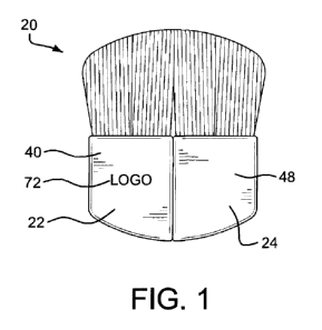
[0034] Referring to the drawings, and initially to FIG. 1, a first form of
cosmetic
brush, indicated generally by the reference numeral 20, may be of any size,
shape or
material without limitation. Cosmetic brush 20 comprises two halves 22 (see
especially FIGS. 6, 7, and 10 through 12) and 24 (see especially FIGS. 8, 9,
and 13
through 15). The two halves 22, 24 are very similar, and in the interests of
conciseness, description of the common features will largely not be repeated.
The few
differences between the two halves 22, 24 are explained in the description
below.
Brush halves 22, 24 each have a head 26, comprising hairs, bristles or fibers,
and a
magnet holder 28, shown separately in FIGS. 16 through 18, received in
respective
casings 30, 32, which also act as handles, shown separately in FIGS. 10
through 12
and 13 through 15.
[0035] As best seen in FIGS. 12 and 15, in this embodiment each of the casings
30, 32 is rectangular in plan view, and is open at the top. The magnet holder
28 is
shaped to fit snugly within the casing 30 or 32, leaving an empty space at the
open top
end 34 of the casing 20. The basal ends 36 of the bristles, hairs, or other
elements
forming the heads 26 are placed in the open top ends 34 of the casings 30, 32,
which
thus act as ferrules to hold the heads 26. The bristles, hairs, or other
elements forming
the heads 26 may be fixed in place in a convenient way, including ways already
known, including by glue or other material that adheres to the inside of the
casings 30,
32, which also secures the magnet holder 28 in position in the casing 30, 32.
[0036] In the embodiment shown in FIGS. 1 through 18 of the drawings, one
narrow side face 38 of the casing 30 of the brush half 22 is flat and smooth
except for
two circular projections 40. The matching narrow side face 42 of the casing 32
of
other brush half 24 has two matching circular recesses 44. The two brush
halves 22,
24 are placed with the matching narrow side faces 38, 42 abutting, and the
projections
40 seated in the recesses 44, to form the assembled brush 20 in the first or
open
configuration as shown in FIGS. 1 and 2. One wide major face 46 of each of the
CA 02755504 2011-09-14
WO 2010/107992 PCT/US2010/027798
-6-
casings 30, 32 is flat and smooth, and is placed against the matching wide
major face
46 of the casing 32, 30 of the other brush half 24, 22 to form a narrower,
thicker
second or folded configuration of the assembled brush 20, as shown in FIGS. 3
through 5, that may be used when storing the brush. As may be seen from the
drawings, the "wide" faces are wider than the "narrow" faces, and in a half-
moon
brush typically two or three times as wide.
[0037] As shown in the drawings, only one narrow side of each brush half 22,
24
is used as the narrow side face 38, 42 that mates with the other brush half
24, 22 in the
open configuration shown in FIGS. 1 and 2. Both the heads 26 and the casings
30, 32
are curved so that in the open configuration they form rounded shapes, giving
the tip
edge of the combined heads 26 a convex "half-moon" shape and the bottom of the
combined casings 30, 32 a convex shape that both echoes the "half-moon" shape
of
the tips visually, and is comfortable to hold. Because of the shaping, it is
immediately
apparent to the ordinary user which side of each brush half 22, 24 is the side
face 38,
42 that mates with the other brush half 24, 22, even without recognizing the
significance of the projections 40 and recesses 44. The projections 40 and
recesses 44
help to hold the two halves correctly aligned in the open configuration, and
to stop the
faces 38, 42 from sliding over each other.
[0038] As will be explained in more detail below, in some embodiments only one
broad side of the casing 30, 32 of each brush half 22, 24 is used as the broad
major
face 46 that mates with the other brush half 24, 22 in the second
configuration. That
face 46 is generally flat and smooth. However, in this embodiment the head 26
is of
constant thickness across its width, so the other broad side 48 of the casing
30, 32 is
also flat and smooth. Optionally, therefore, the sides 46, 48 may be made
different in
appearance. For example, the other broad side 48 may be provided with
decoration or
information, for example, in the form of printed matter 50, that recognizably
identifies
it as the exposed side in the folded configuration. Where the two halves 22,
44 are not
identical, the printed matter may also assist in ensuring that the user has
one half 22
and one half 24, and is not trying to assemble two identical halves 22 or two
identical
halves 24. Alternatively, the brush 20 may be constructed so that either side
46, 48 of
CA 02755504 2011-09-14
WO 2010/107992 PCTIUS2010/027798
-l-
each half 22,24 can be used as the broad major face that engages the other
brush half
in the second configuration.
[0039] The casings 30, 32 may be made of molded plastic material.
[0040] Referring now especially to FIGS. 16 through 18, the magnet holder 28
consists of a solid block of molded plastic material, with several magnetic
elements
50, 52, 54, 56 embedded in it. The magnetic elements may be embedded in the
course
of the molding process, or the block may be molded or machined with recesses
into
which the magnetic elements 50, 52, 54, 56 are subsequently inserted.
[0041] In the embodiment, two magnetic elements 50, 52 are set into a face 58
of
the block 28 that underlies the narrow side face 38, 42 of the casing 30, 32.
The
magnetic elements 50, 52 are one above the other on the vertical centerline of
the
faces 38, 42, 58. Each pair of magnets 50, 50 and 52, 52 on a pair of brush
halves 22,
24 may consist of two permanent magnets or of one permanent magnet and a
magnetically soft ferromagnetic counter-piece. For maximum strength, the
permanent
magnets may be aligned with one pole facing out through the side face 38, 42.
Then,
the two magnets of each pair 50, 50 or 52, 52 need to be oppositely oriented,
and the
two brush halves 22, 24 are different. As shown in FIGS. 1 through 18, the
projections 40 and recesses 44 are also different between the two brush halves
22, 24.
[0042] As shown in FIGS. 1 through 18, the projections 40 and recesses 44 are
similar in size, shape, and placement to the magnets 50, 52 and thus express
visually
the presence of the functional magnets 50, 52. However, other arrangements are
of
course possible.
[0043] Referring also to FIG. 19, in an alternative embodiment the projections
40
and recesses 44 may be omitted, and casings 60 with a flat narrow side face 62
may be
used. It may then be preferred for the narrow side faces 62 to have a textured
finish
64 that resists sliding of the faces 62 out of alignment. Identical brush
halves 22, 24
are possible if the magnets 50, 52 are aligned with their poles facing towards
the
broad faces 46, 48. The magnets then engage side by side, not pole to pole,
and a
weaker connection may result.
CA 02755504 2011-09-14
WO 2010/107992 PCT/US2010/027798
-8-
[0044] In a further alternative, the magnets in brush half 22 may extend
forward
into the projections 40. That arrangement brings the magnets 50, 50 and 52, 52
closer
together, and increases the strength of coupling from any given magnets. The
visible
metal of the magnets may also become a decorative feature. However, that
alternative
complicates manufacture because the assembled holder 28 and magnets 50, 52 can
no
longer be slid as a unit into the casing 30, 32.
[0045] In the embodiment shown in FIG. 18, two magnetic elements 54, 56 are
set
into each of two faces 66 of the block 88 that underlie the broad major faces
46, 48 of
the casing 30, 32. The magnetic elements 54, 56 in each face 66 are side by
side,
roughly at the mid level of the block 28. Each pair of facing magnets 54, 54
and 56,
56 on a pair of brush halves 22, 24 may consist of two permanent magnets or of
one
permanent magnet and a magnetically soft ferromagnetic counter-piece. For
compactness and aesthetic appearance, in the embodiments the second
configuration
has the two brush halves 22, 24 overlying each other with the sides 46
adjacent, so
that the faces 66 of the brush halves 22, 24 that contain the active magnetic
elements
54, 56 are mirror images of one another. For maximum strength, the magnetic
elements 54, 56 may all be permanent magnets aligned with one pole facing out
through the side face 46, 48. Then, the magnets of each pair 54, 54 or 56, 56
can be
identically oriented, and the two brush halves 22, 24 can in this respect be
the same.
[0046] In an alternative embodiment, where the faces 46, 48 of the brush
halves
22, 24 are different, and it is intended that in the second or folded
configuration the
two brush halves shall always be assembled with a specific pair of broad faces
46
adjacent, the magnets 54, 56 maybe inserted in only the side 66 of each holder
28 that
underlies the faces 46. The assembled holders 28 of the two brush halves 22,
24 are
then different. This alternative reduces the number of magnets , and therefore
cost of
materials, used in each brush, but increases the number of different sub-
assemblies,
and therefore may increase the cost of production.
[0047] Where this alternative is applied with magnet holders 28 that are
shaped
before the magnets are inserted, a single sort of magnet holder 28 may be
produced,
with recesses on both sides, and magnets 54, 56 inserted into the recesses on
only one
CA 02755504 2011-09-14
WO 2010/107992 PCT/US2010/027798
-9-
side of each holder 28. The remaining empty recesses do not impair the final
product,
because they are hidden within the casings 30, 32.
[0048] Referring now also to FIG. 20, if only one magnetic element 54 and one
magnetic element 56 is to be included in each holder, an alternative form of
holder 70
may have recesses for the magnetic elements 54, 56 in only one side 66. This
configuration may result from shaping a magnet holder 70 with recesses on only
one
side into which magnetic elements 54, 56 are subsequently inserted, or molding
the
holder block 70 onto only one magnetic element 54 and one magnetic element 56.
The holders 70 may be made in mirror-image pairs or, in order to simplify
manufacture, the holders 70 can be made identical. The magnetic elements 54,
56
then either extend through the whole thickness of the block 70, or are
sufficiently
strong to attract across the part of the thickness of the block 70 through
which they do
not extend. As was explained above, if all the assembled holders 70 are
identical the
magnetic elements 54, 56 should be permanent magnets. If two different sorts
are
produced for brush halves 22, 24, then one magnetic element of each pair 54,
54, and
56, 56 can be a magnetically soft counter-piece.
[0049] In use, the user is provided with a matched pair of brush halves 22,
24. To
form a broad, thin half-moon brush 20 in the first configuration as shown in
FIG. 1,
the user aligns the brush halves 22, 24 so that the tips of the heads 26 form
the desired
half-moon shape, and places the narrow side faces 38, 42 or 62, 62 together.
The
projections 40, if present, seat in the recesses 44. The pairs of magnetic
elements 50,
50 and 52, 52 then engage magnetically, both holding the two brush halves 22,
24
together and holding them in the correct relative position. Printed matter 72
on one or
both of the broad faces 46, 48 may confirm the correct relative position. The
user may
then use the assembled "half-moon" brush to apply cosmetics.
[0050] To form a thicker but less broad brush 20 in the second or folded
configuration, the user aligns the brush halves 22, 24 face to face, and
places the broad
major faces 46 together. The pairs of magnetic elements 54, 54 and 56, 56 then
engage magnetically, both holding the two brush halves 22, 24 together and
holding
them in the correct relative position for the second configuration. The brush
20 in the
CA 02755504 2011-09-14
WO 2010/107992 PCT/US2010/027798
-10-
second configuration maybe used to apply cosmetics, or may be stored more
compactly than in the first configuration. The more compact shape may simplify
providing a suitable place for storage, especially in a makeup kit containing
assigned
compartments or holders for different brushes, applicators or cosmetic
materials. The
more compact shape may reduce the risk of damage in storage.
[0051] As an example of suitable dimensions for cosmetic brushes, the brush or
applicator 20 may be around 40 mm (1 %Z") high, measured at the highest point
along
the side 38, 42, of which half maybe the visible height of the head 26, and
half may
be the height of the casing 30, 32. Each brush half 22, 24 may be around 16 mm
(2/3") wide, giving the brush 20 in the first configuration of FIG. 1 a total
width of
around 32 mm (11/4"). Each brush half 22, 24 maybe around 6 mm ('/4") thick,
which
is also the thickness of the brush 20 in the first configuration of FIG. 1.
The brush in
the second configuration is thus around 16 mm wide and 12 mm thick. The walls
38,
42, 46, 48 of the casing 30, 32 may be around 0.6 mm (0.025") thick, taking
into
consideration both mechanical strength and the reduction in magnetic
attraction as the
space between the magnetic elements increases. The bottom wall and the outer
side
wall 48 of the casings maybe the same thickness, for convenience of design,
molding,
and assembly. The four walls may be slightly tapered, for easier demolding,
but it is
preferred for any taper to be too slight to be apparent to an ordinary user.
The bottom
wall of the casing 30, 32 may be the same thickness or thicker. The magnet
holder 28
is dimensioned to fit inside the bottom of casing 30 or 32 without rattling,
and may
leave about 6 mm ('/4") of space in the top 34 of casing 30, 32 for mounting
the bases
36 of the bristles or hairs of head 26. The magnetic elements 50, 52, 54, 56
may be
circular, and around 4.1 mm (0.16") in diameter, and 1.6 mm (0.06") thick. The
projections 40 may be around 0.3 mm (0.01") high, and the corresponding
recesses 44
maybe around 0.3 mm deep.
[0052] The disclosures of each patent, patent application and publication
cited or
described in this document are hereby incorporated herein by reference, in
their
entirety.
CA 02755504 2011-09-14
WO 2010/107992 PCT/US2010/027798
-11-
[0053] While the foregoing specification has been described with regard to
certain
preferred embodiments, and many details have been set forth for the purpose of
illustration, it will be apparent to those skilled in the art without
departing from the
spirit and scope of the invention, that the invention may be subject to
various
modifications and additional embodiments, and that certain of the details
described
herein can be varied considerably without departing from the basic principles
of the
invention. Such modifications and additional embodiments are also intended to
fall
within the scope of the appended claims and their equivalents.
[0054] For example, expressions of orientation such as "top" and "bottom" have
been used with reference to the orientation of the brush 20 and brush halves
22, 24 as
shown in various figures of the drawings. The brush may of course be held,
stored,
and used in any orientation.
[0055] Several possible variants in the arrangement of the magnetic elements
50,
52, 54, 56 have been noted above. Other variants are possible. For example, it
is
apparent from FIG. 16 that there is room for the magnets 54, 56 to be placed
differently, or for the number of magnets to be different. If it is desired to
use the
brush 20 in combination with the stand described in commonly-assigned U.S.
Patent
Application No. 2007-0199575, then the magnets 54, 56 may be positioned
appropriately for a specific stand.
[0056] The magnets shown in the drawings are circular, with their poles on the
end faces. If it is desired for the polar direction of a magnet to lie
parallel, rather than
perpendicular, to the adjacent surface of casing 30, 32, then a different
shape may give
a better distribution of magnetic flux, and/or may assist in orienting the
magnet
correctly.
[0057] Although the second configuration shown in FIGS. 3 through 5 has been
described as a "folded" configuration, the two brush halves 22, 24 are
separate, and
are typically separated and reassembled when changing between the first and
second
configurations. A hinge, which may be a living hinge, could be provided that
allowed
actual folding between the two configurations.
CA 02755504 2011-09-14
WO 2010/107992 PCTIUS2010/027798
-12-
[0058] In FIGS. 1 through 18, projections 40 and recesses 44 are on narrow
side
faces 38, 42. Similar recesses could instead, or in addition, be provided on
broad
faces 46. However, if the second or folded configuration is used only for
storage,
such additional projections and recesses are usually not important, and they
may make
the brush 20 less comfortable to hold in the first or open configuration.
[0059] Although the brush 20 has been described as a "half-moon" brush, and
shown in the drawings with a convex head 26, the outline of the tip edge of
the head
may be of any desired shape for a specific application. An applicator other
than a
brush, with a head 26 other than bristles, is also possible.
[0060] Although specific embodiments have been described, the skilled person
will understand how features of different embodiments may be combined. For
example, the various options for magnets 50, 52 may be chosen independently of
the
options for magnets 54, 56, or maybe coordinated so that a single type of
magnet can
be used throughout. If it is desired for the two brush halves 22, 24 to be
identical,
then an appropriate combination of choices may be made.