Note: Descriptions are shown in the official language in which they were submitted.
CA 02755564 2016-11-17
PATENT APPLICATION
CASING BIT AND CASING REAMER DESIGNS
TECHNICAL FIELD
The present invention relates generally to drilling a wellbore, and more
particularly to the drilling tools used at the end of a casing or liner within
the wellbore. The
present invention concerns drilling tools (and methods for forming drilling
tools) that are
attachable to a casing or liner string. In the context of the present
invention, the terms casing and
liner are used interchangeably.
BACKGROUND
In conventional drilling techniques, a longitudinally extending string
comprising
sections of drill pipe is secured to a drill bit of a larger diameter than the
drill pipe. After a
selected portion of the wellbore has been drilled, the drill string is removed
and a string of
tubular members of lesser diameter than the wellbore, known as a casing
string, is placed in the
1
CA 02755564 2011-09-14
WO 2010/141781 PCT/US2010/037330
wellbore. The annulus between the wall of the wellbore and the outside of the
casing string is
then filled with cement by pumping the cement down through a casing shoe or
reamer shoe
disposed at the end of the casing string.
In an alternative technique, designed to address the inefficiencies associated
with
making multiple wellbore trips in the conventional drilling technique
discussed above, it is now
known to drill with casing. In this technique, the drilling operation employs
a drill bit, termed a
casing bit, which is attached to the end of the casing string. The casing bit
functions not only to
drill the earth formation, but also to guide the casing string into the
wellbore. The casing bit
remains in place during subsequent cementing of the casing in place. The
casing string is thus
run into the wellbore as the wellbore is being formed by the casing bit. This
eliminates the need
for one or more extra trips to retrieve a drill string and drill bit after
reaching a target depth
where cementing is desired.
In either technique, additional drilling beyond the end depth of the casing
string
may be required. If so, the operator must drill out the casing end tool (shoe
or bit) to reach the
underlying formation. This is typically accomplished with a mill bit that is
specifically designed
to cut through the material from which the shoe is made. This has led to the
development of
casing end tools that are more readily drilled out. Primarily, such end tools
use an aluminum
alloy as the parent body material for the reamer nose or the cutting structure
carrying face of the
end tool. More recently, casing end tools made of alloyed steel have been
commercialized and
are run on casing prior to being drilled out with specially designed drill out
PDC bits that carry
an additional, standalone, overexposed tungsten carbide cutting structure to
accomplish the drill
out.
2
CA 02755564 2016-11-17
Prior art efforts relating to casing operations are set forth below.
U.S. Patent No. 6,062,326 to Strong et al discloses a casing shoe/reamer with
cutting means. The shoe/reamer has flutes (blades) that in one embodiment
carry PDC cutters
along the gage and across the nose of the tool. The tool is disclosed as being
made either from
drillable aluminum or non-drillable material. In one embodiment the nose
section is designed to
be segmented with the segments being hinged to the outer portion of the tool
so the nose
segments can be pushed out and forward prior to cementing or as part of the
cementing process.
U.S. Patent Nos. 6,401,820 and 6,659,173 to Kirk et al describe a shoe with
reaming members and a nose portion of aluminum or zinc alloy to allow the nose
to be drilled
out.
U.S. Patent No. 6,443,247 to Wardley describes a casing drilling shoe with an
outer drilling section constructed of a hard material such as steel and an
inner section constructed
of a readily drillable material such as aluminum. It further includes a device
for displacing the
outer drilling section radially outwardly.
U.S. Patent No. 6,848,517 to Wardley describes a drillable drill bit nozzle
for use
in a drill bit that is going to be drilled out.
U.S. Patent No. 7,066,253 to Baker describes a casing shoe or reamer shoe with
an outer body of relatively hard material and a nose of relatively soft
material which are
interlocked. A following drill bit is used to drill out the majority of the
soft material leaving a
sheath of the soft material in the internal circumference of the hard
material.
U.S. Patent No. 7,096,982 to McKay et al discloses a drill shoe with a body
constructed of a relatively soft material which is set with blades of a
relatively hard material.
3
CA 02755564 2011-09-14
WO 2010/141781 PCT/US2010/037330
The blades, typically steel, are further set with PDC cutters. Once the
desired depth of drilling
has been achieved, a displacement element is activated to push out the soft
material and bend the
blades to the sidewalls of the annulus. The displacement element can then be
drilled out with a
following bit. McKay wants to provide a cutting structure support mechanism
with the steel
blades strong enough to handle drilling loads.
U.S. Patent No. 7,117,960 to Wheeler et al describes a bit for drilling with a
completion string that incorporates an integrated female non-shouldered
oilfield completion
string thread. The specification describes the bit as being manufactured from
a material which
does not allow the bit to be readily drilled.
U.S. Patent No. 7,216,727 to Wardley discloses a casing drilling bit
constructed
from a relatively soft material such as aluminum, copper, or brass alloy and
is coated with
relatively hard material. The cutting means of the cutting members consist of
fine layers or
cutting elements formed from hard material.
U.S. Patent No. 7,395,882 to Oldham et al is for "Casing and Liner Drilling
Bits".
This patent teaches making such tools with an axisymmetric inner profile to be
evenly addressed
by a subsequent drilling bit. It also teaches using nozzles deployed with
sleeves, and gage
sections that extend over the casing to which the tool is attached.
U.S. Patent Application Publication No. 2007/028972 to Clark et al is for
"Reaming Tool Suitable for Running on Casing or Liner and Method of Reaming".
This
published application also teaches an axisymmetric inner profile and further
states "....the
absence of blades in the nose area projecting above the face of the nose
allows for an
uninterrupted cut of material of the body shell in the nose, making the
reaming tool PDC bit-
drillable."
4
CA 02755564 2016-11-17
U.S. Patent No. 6,845,816 to Kirk et al teaches the use of an austemperized
ductile iron (ADI) material for a centralizer. This material is more robust
than aluminum and
lighter than and more machinable than steel. See also, for example, ADI
materials provided for
sale by THDick.
Reference is also made to the Baker Hughes (Hughes Christensen) EZ Case
Casing Bit System and the Weatherford International DrillShoe tools used for
drilling with
casing prior art devices.
To summarize the prior art in this area, great attention has been given to the
eventual drill out of the casing end tool, but little attention has been paid
to the drilling efficiency
of the casing end tool itself. Significant improvements to casing end tool
performance can be
made by adapting efficient drilling technology to the unique challenges of
casing end tool
structure and architecture. The other significant trade off in the prior art
is in the choice of body
material. Aluminum is readily drilled out but has a low resistance to erosion
and abrasion, and
cannot take the level of loading that steel is able to absorb. Alternatively,
steel is more robust
than aluminum but is much more difficult to drill out. If casing equipment is
to be drilled out
with a PDC bit then this has required the use of specially designed PDC drill
out bits that
compromise bit performance in the rock formations encountered after drill out.
What is needed are casing end tools (including casing bits and reamer shoes,
liner
drill in bits, liner reamers, and liner or casing mud motor driven reamers or
mills) that perform
effectively while drilling or reaming, are resistant to erosion, abrasion, and
impact damage, and
that can be effectively and consistently drilled out using standard PDC drill
bits or cutter
protected PDC bits.
CA 02755564 2011-09-14
WO 2010/141781 PCT/US2010/037330
SUMMARY
Casing end tools used for casing drilling and reaming or liner drill in or
reaming
are presented which overcome many of the previously noted shortfalls of the
prior art. These
tools employ advanced design and manufacturing techniques not previously
practiced on casing
end tools. A preferred, but non-limiting, embodiment of a casing bit is
described. A casing
reamer embodiment is also described.
Several approaches are incorporated in the construction of the superabrasive
cutting elements for the casing end tool. These cutter element configurations
are intended to
reduce the total volume of tungsten carbide substrate material that has to be
crushed, pushed
aside, or flushed up hole as a part of the drill out of the casing end tool.
In a typical
superabrasive cutting element, the vast majority of its length is made of
tungsten carbide. In a
preferred embodiment of the casing end tool, an included cutter uses a short
substrate. An
alternative embodiment uses a short tungsten carbide substrate, bonded to an
additional length of
alternative substrate material such as steel or vanadium carbide. This allows
for casing end tools
that are designed around cutters of a traditional total length while reducing
the total amount of
hard cemented tungsten carbide material to be encountered during drill out.
In a preferred embodiment, the PDC or other superabrasive cutting element
cutting structure is designed to be force balanced to within less than 10%, or
less than 7%, or less
than 5%, or less than 2%.
In an embodiment the casing end tool employs partially shallow leached or
partially deep leached PDC cutters. In an embodiment the casing end tool
employs fully leached
cutters that have been reattached to a metal substrate through a second high
pressure and high
temperature (HP/HT) press cycle.
6
CA 02755564 2011-09-14
WO 2010/141781 PCT/US2010/037330
In an embodiment the casing end tool employs a cutter layout that has trailing
or
leading redundant, tracking, or plural cutters. These cutters may be mounted
on the same blade
as a set of primary cutters or may be mounted on a separate and distinct blade
or blades.
In an embodiment the casing end tool uses cutter back up structures. These
cutter
back up structures may be cast from the parent body material or may be
manufactured separately
and pressed, glued or brazed in. These structures may be made of steel,
tungsten carbide,
vanadium carbide, tungsten carbide matrix, domed superabrasive, or may be
diamond
impregnated segments. The cutter back up structures may be slightly
overexposed, equally
exposed, or underexposed in comparison to their corresponding primary cutter.
The cutter back
up structures may be at the same radial distance, or at a slightly greater
distance, or at a slightly
lesser distance from bit centerline than their corresponding primary cutter.
In an embodiment the casing end tool uses a large number of ports or sleeved
ports. If sleeves are used they may be made of thin walled tungsten carbide,
vanadium carbide,
ceramic, or steel. The casing end tool of this invention purposefully does not
use replaceable or
threaded nozzles to choke flow and create higher hydraulic horsepower per
square inch, but
rather relies on flow rate through a large number of relatively large inner
diameter sleeved ports
for cleaning and drilling efficiency while reducing the incidence of bit body
erosion. In an
embodiment the port sleeves are highly extended into the inner plenum of the
casing end tool to
move the active area of erosive flow away from the inner concave surface of
the tool.
In an embodiment the casing end tool does not have a regular axisymmetric
inner
profile, but rather a non-axisymmetric pattern of raised bosses or lands
creating an uneven,
undulating and irregular surface (it being understood that "axisymmetric"
means "exhibiting
symmetry around an axis; or exhibiting cylindrical symmetry"). The point here
is to increase the
7
CA 02755564 2011-09-14
WO 2010/141781 PCT/US2010/037330
amount of interrupted cut during drill out (by an axisymmetric mill/drill bit)
to stress the center
part of the bit body and improve fragmentation during drill out. At least some
of the raised
bosses or lands are meant to provide increased contact and support area if
highly extended port
sleeves are used. In an embodiment the raised lands coincide with channels
cast into or
machined into the casing end tool nose or face. On a bladed bit the internal
lands radiate out
generally from the center and alternate with internal channels. Each internal
land is positioned to
generally correspond with an external facial fluid channel, while an internal
channel is positioned
to generally correspond with an external facial blade. Even in this instance
the preferred
embodiment is non-axisymmetry of the height and radial layout of the internal
lands. During
drill out the lands are drilled first thus increasing the likelihood of break
up and fragmentation of
the corresponding raised facial features on the nose or face of the casing end
tool when it is
drilled out.
In any of the bladed embodiments slits may be cut or cast in between some of
the
cutter pockets to increase the rate of fragmentation during drill out. In any
of the embodiments
blind holes may be drilled or cast into the face of the casing end tool. These
holes do not break
into the plenum of the tool. The purpose of the holes is to create interrupted
cuts and fracture
points across the casing end tool face to accelerate the break up and
fragmentation of the end tool
face during drill out.
In an alternative embodiment the inner concave surface is an axisymmetric
inner
profile.
Embodiments of casing end tools that will be used as reamers may or may not
have cutters deployed across the full nose or face of the tool. Embodiments of
casing end tools
that will be used as reamers may have eccentric noses, or symmetric noses. If
concentric, the
8
CA 02755564 2011-09-14
WO 2010/141781 PCT/US2010/037330
nose or face may have a concave "cone" section. Alternative embodiments of
casing end tools
intended for use as reamers may use domed superabrasive cutting elements, or
tungsten carbide
domes, rather than flat faced cutting elements. Domed elements create less
torque and are less
likely to bite into the borehole wall. In an embodiment a centralizing inner
collar of aluminum,
phenolic, or similar is employed to stabilize the drill out bit during drill
out of the casing end
tool.
In a preferred embodiment the primary material used to manufacture the body of
the casing end tool is made of an austemperized ductile iron (ADI) material.
In an embodiment the casing end tool is manufactured using an aluminum or
aluminum alloy material.
In an alternative embodiment the casing end tool primary body is manufactured
using a copper, brass, zinc alloy, steel, or titanium material.
In another embodiment the casing end tool primary body is cast from
crystalline
tungsten infiltrated with a brass binder. In this embodiment the parent body
material may be
"graded" with the inclusion of a volume of tungsten carbide powder or paste
deployed on the
outermost surface followed by a layer or layers of mixed tungsten carbide and
crystalline
tungsten ultimately ending with pure crystalline tungsten covering the
distance to the inner
concave surface of the casing end tool. The purpose of the graded powder
layers is to enhance
the erosion resistance of the nose or face of the tool while using highly
machinable crystalline
tungsten for the majority of the powder mix in the tool body casting. By
grading the material an
abrupt transition from a soft material to a hard material during drill out is
avoided. In this
infiltration embodiment an outer cylindrical shell is typically made of steel.
This steel cylinder
acts as the blank or casting mandrel as is known in the art. Typically a blank
makes up the
9
CA 02755564 2011-09-14
WO 2010/141781 PCT/US2010/037330
central body of an infiltrated drill bit. In the case of this invention the
blank is a cylinder that is
placed around the periphery of the milled facial features in a graphite
casting mold. The steel
cylinder may be fitted into a machined groove in the mold to accurately locate
it relative to the
facial features. When the mold is loaded with tungsten carbide, or crystalline
tungsten or both
the infiltration metal, typically a nickel brass alloy is positioned to
infiltrate down into the
powder(s) in a furnace cycle. Preferably the lower end of the steel blank
cylinder is channeled
and/or grooved to create a positive lock with the cast face of the tool. Any
excess steel of the
cylinder which protrudes below the face of the casting may be machined off The
great
advantage of this embodiment is that it can take advantage of existing
materials, design software,
casting methods, and machine tools used in the manufacture of tungsten carbide
matrix drill bits.
In an alternative embodiment, the casing end tool incorporates a float valve
for
use in cementing operations. In an alternative embodiment, the casing end tool
employs a float
valve that is offset from center to improve the drillability of the float
valve.
In an embodiment, the casing end tool incorporates one or more frangible zones
or bypass ports to provide an additional passage area for the flow of cement
out of the casing end
tool during the cementing of the casing.
In an embodiment, the body of the casing end tool is nitride treated to alter
the
surface electrical charge so as to enhance bit cleaning.
In an embodiment, the gage sections of the casing end tool are narrower in the
uphole direction than they are in the downhole direction.
In an embodiment, the cutters on the casing end tool are deployed in pairs
resulting in more, but shorter, blade sections. These blade sections are more
likely to break up
into smaller pieces during drill out making them easier to flush out of the
hole.
CA 02755564 2011-09-14
WO 2010/141781 PCT/US2010/037330
In an embodiment, the central portion of the casing end tool is made by laser
cutting or wire Electro Discharge Machining a cylinder, preferably of the
parent body material,
into pieces. These pieces are then tightly clamped together and machined for
blades, pockets,
and internal surface. The outer diameter is then threaded so that the center
piece can be turned in
a clockwise manner into a mating thread on the face of the main tool body,
preferably stopping at
an internal shoulder. When drilling downhole the forces on the cutter faces
keep the center
locked into the tool. Upon drill out by a following bit as the bit begins to
machine away the
internal surface of the casing end tool it will put torque on the threaded
face insert to unscrew it
in a counter-clockwise manner and allow it to come apart in more readily
broken and flushed
pieces.
In an embodiment, the casing end tool of the present invention is operated in
conjunction with non-rotating casing centralizers to improve the transmission
of weight and
torque to the casing end tool.
In an embodiment, the cutters of the casing end tool are fitted with
protective
caps. In this instance the casing end tool has an enhanced capability of
performing drill out
through float equipment or a previously run and cemented casing end tool, or
both.
In an embodiment, the upper gage sections of the casing end tool are set with
up
drill PDC cutters or other hard or superabrasive up drill cutting structure.
BRIEF DESCRIPTION OF THE DRAWINGS
Figure 1 is a simplified schematic cross-sectional illustration of a casing
end tool
in the form of a casing bit;
11
CA 02755564 2011-09-14
WO 2010/141781 PCT/US2010/037330
Figure 2A is a side view of one embodiment of a cutter for use the tool of
Figure
1;
Figure 2B is a side view of another embodiment of a cutter for use in the tool
of
Figure 1;
Figure 3 is a simplified schematic cross-section illustrating that the
position of
some raised bosses/lands coincides with channels in the casing end tool nose
or face;
Figure 4 is a plan view of the internal surfaces of a casing bit of Figure 1;
Figure 5 is a plan view of the casing end tool of Figure 1;
Figure 6A is a plan view of the casing end tool of Figure 1 similar to that
shown
in Figure 4;
Figure 6B is a partial broken-away sectional view of Figure 6A;
Figure 7 is a casing reamer;
Figure 8 is a simplified schematic cross-sectional view of a casing bit (as
shown
in Figure 1, for example) further including an inner collar;
Figure 9 is a simplified schematic cross-sectional illustration of another
embodiment of a casing bit;
Figure 10 is a plan view of the face of the bit shown in Figure 9; and
Figure 11 is a side view of a cutter in accordance with another embodiment.
DETAILED DESCRIPTION OF THE DRAWINGS
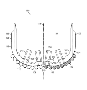
Reference is now made to Figure 1 which shows a cross-sectional illustration
of a
casing end tool in the form of a casing bit 100 in accordance with an
embodiment of the
invention. The casing bit 100 has a bowl-like or cup-like configuration with
an inner concave
12
CA 02755564 2011-09-14
WO 2010/141781 PCT/US2010/037330
surface 102 defining a central plenum region and an outer convex surface 104.
The inner and
outer surfaces define opposed sides of a wall which surrounds the central
plenum region.
Formed on the outer convex surface 104 of the casing bit 100 are a number of
blades 106. Each
blade 106 supports a plurality of cutters 108. The dark shaded cutters 110 in
the illustration are
oriented on a first blade 106 with their diamond tables facing the viewer,
while the light shaded
cutters 112 in the illustration are oriented on another blade 106 (for
example, radially opposite
the first blade) with their diamond tables facing away from the viewer. The
blades 106 extend
outwardly from a central rotational axis 114 of the casing bit 100 to define
the gage 116 of the
bit. Junk slots 118 for the casing bit are positioned between blades 106.
In a preferred embodiment, the primary material used to manufacture the body
of
the casing end tool is austemperized ductile iron (ADI). In an embodiment, the
casing end tool is
manufactured using an aluminum or aluminum alloy material. In an alternative
embodiment, the
casing end tool primary body is manufactured using a copper, brass, zinc
alloy, steel, or titanium
material.
In another embodiment, the casing end tool primary body is cast from
crystalline
tungsten infiltrated with a brass binder. In this embodiment the parent body
material may be
"graded" with the inclusion of a volume of tungsten carbide powder or paste
deployed on the
outermost surface followed by a layer or layers of mixed tungsten carbide and
crystalline
tungsten ultimately ending with pure crystalline tungsten covering the
distance to the inner
concave surface of the casing end tool. The purpose of the graded powder
layers is to enhance
the erosion resistance of the nose or face of the tool while using highly
machinable crystalline
tungsten for the majority of the powder mix in the tool body casting. By
grading the material an
13
CA 02755564 2016-11-17
abrupt transition from a soft material to a hard material during drill out of
the wall of the tool is
avoided.
In this infiltration embodiment an outer cylindrical shell of the bit is
typically
made of steel. This steel cylinder acts as the blank or casting mandrel as is
known in the art.
Typically a blank makes up the central body of an infiltrated drill bit. In
this instance, the blank
is a cylinder that is placed around the periphery of the milled facial
features in a graphite casting
mold. The steel cylinder may be fitted into a machined groove in the mold to
accurately locate it
relative to the facial features. When the mold is loaded with tungsten
carbide, or crystalline
tungsten or both the infiltration metal, typically a nickel brass alloy is
positioned to infiltrate
down into the powder(s) in a furnace cycle. Preferably the lower end of the
steel blank cylinder
is channeled and/or grooved to create a positive lock with the cast face of
the tool. Any excess
steel of the cylinder which protrudes below the face of the casting may be
machined off. The
great advantage of this embodiment is that it can take advantage of existing
materials, design
software, casting methods, and machine tools used in the manufacture of
tungsten carbide matrix
drill bits.
In an alternative embodiment, the casing bit incorporates a float valve for
use in
cementing operations. In an alternative embodiment, the casing end tool
employs a float valve
that is offset from center to improve the drillability of the float valve.
Sec, for example,
Published U.S. Application for Patent No. 2007/0246224.
Several approaches are incorporated in the construction of the superabrasive
cutting elements for the casing end tool of Figure 1. These cutter element
configurations are
intended to reduce the total volume of tungsten carbide substrate material
that has to be crushed,
14
CA 02755564 2016-11-17
pushed aside, or flushed up hole as a part of the drill out of the casing end
tool. Typical
superabrasive cutting elements are 13mm in diameter and 13mm in length. The
vast majority of
the 13mm length is of tungsten carbide.
Figure 2A shows a side view of one embodiment of a cutter 108 for use the tool
of Figure 1. This cutter, for example with a diameter ranging from 8mm and
19mm, uses a short
tungsten carbide substrate 200 (for example, resulting in a total cutter
length of 8mm, or 5mm, or
3mm). The cutter further includes a diamond layer (table) 202.
Figure 2B shows a side view of another embodiment of a cutter 108 for use in
the
tool of Figure 1. This cutter also has a short tungsten carbide substrate 200.
However, if a
longer cutter is needed, the short tungsten carbide substrate 200 is bonded to
an additional length
of alternative substrate material 204 such as steel or vanadium carbide. This
allows for casing
end tools that are designed around cutters of a traditional total length to
use cutters which reduce
the total amount of hard cemented tungsten carbide material to be encountered
during drill out.
The cutters of Figures 2A and 2B may employ diamond layers 202 that are
partially shallow leached or partially deep leached (see, for example, U.S.
Patent Nos. 6,861,098,
6,861,137, 6,878,447, 6,601,662,6,544,308, 6,562,462, 6,585,064, 6,589,640,
6,592,985,
6,739,214, 6,749,033, and 6,797,326.
In an alternative embodiment, the cutters of Figures 2A and 2B employ fully
leached
diamond tables 202 that have been reattached to the substrate 200 through a
second high
pressure/high temperature (HP/HT) press cycle (see, for example, U.S. Patent
No. 5,127,923.
Reference is once again made to Figure 1. The casing end tool includes a large
number of ports 130. If desired, each port may comprise a sleeved port 132. If
a port sleeve 132
CA 02755564 2011-09-14
WO 2010/141781 PCT/US2010/037330
is used for a given port 130, the sleeve may be made of thin walled tungsten
carbide, vanadium
carbide, ceramic, or steel. The casing end tool purposefully does not use
replaceable or threaded
nozzles which can choke flow and create higher hydraulic horsepower per square
inch. Instead,
the tool relies on flow rate through a large number of relatively large inner
diameter ports 130
(sleeved ports 132) for cleaning and drilling efficiency while reducing the
incidence of bit body
erosion. In an embodiment the port sleeves 132 are highly extended into the
inner plenum 134 of
the casing end tool to move the active area of erosive flow away from the
inner concave surface
102 of the tool.
In an embodiment the casing end tool does not have a regular or symmetric
inner
concave surface 102 profile but rather has an inner concave surface 102 with a
non-axisymmetric
pattern of raised bosses 140 or lands. This creates an uneven, undulating
inner concave surface
and thus an irregular inner profile. The point of this feature is to increase
the amount of
interrupted cut in the total bit body during drill out by a mill/drill bit
which would present an
axisymmetric face in contact with the inner concave surface 102. This will
stress the center part
of the tool bit body and improve fragmentation of the casing end tool during
drill out. It will
thus be much easier for the drill out operation to be completed. The outer
convex surface 104 of
the tool, on the contrary defines an axisymmetric shape.
In an alternative embodiment, the inner concave surface 102 of the casing end
tool may have an axisymmetric inner profile which preferably does not match
the axisymmetric
face of the mill/drill bit.
At least some of the raised bosses 140 or lands provide an additional function
in
that they increase the thickness of the casing end tool structure at and
around the ports 130. This
is important to provide increased contact and support area if highly extended
port sleeves 132 are
16
CA 02755564 2016-11-17
used. The port sleeves 132 extend, for example, at least 1/4" from the
surrounding raised boss
140 or land.
In an embodiment the body of the casing end tool is nitride treated to alter
the
surface electrical charge to enhance bit cleaning. See, for example, U.S.
Patent No. 5,330,016..
In an embodiment the gage sections 116 of the casing end tool have a width
that
narrows in the uphole direction from the downhole direction. See, for example,
U.S. Patent No.
4,696,354. This is not explicitly shown in Figure 1.
The casing end tool may incorporate one or more frangible zones or bypass
ports
to provide an additional passage area for the flow of cement out of the casing
end tool during the
cementing of the casing.
In an embodiment, the casing end tool of the present invention is operated in
conjunction with non-rotating casing centralizers to improve the transmission
of weight and
torque to the casing end tool. See, for example, U.S. Patent No. 5,797,455.
In an embodiment, the position of some of the raised bosses/lands 140
coincides
with channels 150 in the outer surface 104 that are cast into or machined into
the casing end tool
nose or face 152. This is shown in the cross-section of Figure 3. The ports
and port sleeves are
omitted from Figure 3 for reasons of clarity. The raised boss/land 140 with
corresponding
channel 150 is provided to create an uneven, undulating inner concave surface
102 (with an
irregular inner profile) so as to increase the amount of interrupted cut of
the body during drill out
and support improved fragmentation of the casing end tool during drill out.
The channels 150
17
CA 02755564 2016-11-17
are formed on the outer convex surface 104, while channels 154 are formed on
the inner concave
surface 102. Preferably, when included on both surfaces, the position of the
channels 150 and
154 is offset as shown.
Reference is now made to Figure 4 which shows a plan view of the casing bit
100
of Figure 1. The view in Figure 4 is looking into the bowl-like or cup-like
configuration towards
the inner concave surface 102. The raised bosses 140 are generally shown with
a circular/oval
shape as a matter of convenience and not limitation as the bosses can take on
any desired shape
which supports the formation of a non-axisymmetric pattern on the inner
concave surface. The
illustration of an oval shape, as opposed to circular shape, is provided to
indicate that the boss
feature of interest is located more on a side inside surface than a bottom
inside surface of the
tool. Figure 4 further shows how a boss 140 has been associated with the
location of each highly
extended port sleeve 132.
Reference is now made to Figure 5 which shows a plan view of the casing end
tool of Figure 1. The view in Figure 5 is looking at the face (outer convex
surface 104) of the bit
100. The bit includes a plurality of blades 106, each having a spiral
configuration. It will be
noted that the blades 106 could, alternatively, be straight blades as known in
the art. The layout
of the blades 106 is asymmetric, but it will be understood that a symmetric
blade could
alternatively be used.
In an embodiment, as shown in Figure 5, the casing bit 100 employs a cutter
layout on one or more blades that has trailing or leading redundant, tracking,
or plural cutters
160. See, for example, U.S. Patent Nos. 5,549,171, 5,551,522, 5,582,261, and
5,651,421.
These cutters 160 may be mounted on the
18
CA 02755564 2016-11-17
same blade as a set of primary cutters 108 or may be mounted on a separate and
distinct blade
106 or blades.
In an embodiment, the cutters 108 on the casing bit are deployed in pairs
resulting
in more but shorter blade sections. See, for example, U.S. Patent Nos.
4,714,120.
These blade sections are more likely to break up
into smaller pieces during drill out making them easier to flush out of the
hole.
In an embodiment, as shown in Figure 5, the casing bit 100 includes on at
least
one blade a set of cutter back up structures 170. See, for example, U.S.
Patent Nos. 5,090,492,
5,244,039, 4,889,017, and 4,823,892.
The cutter back up structures 170 may be cast from the parent body material or
may be
manufactured separately and pressed, glued or brazed in. These structures may
be made of steel,
ADI, tungsten carbide, vanadium carbide, tungsten carbide matrix, crystalling
tungsten matrix,
domed superabrasive, or may be diamond impregnated segments. The cutter back
up structures
170 may be slightly overexposed, equally exposed, or underexposed in
comparison to their
corresponding primary cutter. The cutter back up structures 170 may be at the
same radial
distance, or at a slightly greater distance, or at a slightly lesser distance
from bit centerline than
their corresponding primary cutter 108.
In an embodiment the upper gage 116 sections of the casing end tool are set
with
up drill PDC cutters or other hard or superabrasive up drill cutting
structure.
In a preferred embodiment, the casing bit 100 includes a PDC or other
superabrasive cutting element cutting structure that is designed to be force
balanced. See, for
example, U.S. Patent Nos. 4,815,342, and 5,042,596.
19
CA 02755564 2016-11-17
=
Such force balancing is preferably designed to be within less than 10%, or
less
than 7%, or less than 5%, or less than 2%.
Force balancing may be performed with respect to the bit under several
different
(or over a range of) cutting conditions.
In an embodiment wherein the casing end tool is a reamer to be used in an
existing wellbore, force balancing is accomplished by assuming incremental
constriction
diameters. For instance a simulated tool run of the reamer is performed
assuming a .125"
reduction in the original hole diameter and the tool is force balanced to
reflect the cutting done at
the assumed constriction diameter. Afterwards further simulated tool runs are
performed
assuming greater reductions in the original hole size with force balancing
being performed at
each step. Eventually the reamer design is force balanced across a range of
anticipated hole
diameters so that in application of the actual reamer it will be force
balanced for the actual
constriction diameter that exists in the wellbore. See, U.S. Patent
Application Publication No.
2010/0051349.
Reference is now made to Figure 6A which shows a plan view of the casing end
tool of Figure 1 similar to that shown in Figure 4. The view in Figure 6A,
like that of Figure 4,
is looking into the bowl-like or cup-like configuration towards the inner
concave surface 102.
On a bladed bit the provision of groups 180 of internal bosses/lands 140
radiate out generally
from the center. These groups of lands 140 alternate with an internal channel
182 formed in the
inner concave surface 102 of the bit. In this configuration, a group 180 of
internal bosses/lands
generally corresponds with an external facial fluid channel (junk slot). Each
of the included
internal channels 182 generally corresponds with an external facial blade 106.
Even in this
instance the preferred embodiment is non-axisymmetric of the height and radial
layout of the
CA 02755564 2011-09-14
WO 2010/141781 PCT/US2010/037330
internal lands. During drill out the lands are drilled first by the
axisymmetric face of the
mill/drill bit thus increasing the likelihood of break up and fragmentation of
the corresponding
raised facial features on the nose or face of the casing end tool. A partial
broken-away sectional
view of Figure 6A is provided in Figure 6B.
In any of the bladed embodiments described above, slits 190 may be cut or cast
in
the blades 106 between some of the cutter pockets, as shown in Figure 5, in
order to increase the
rate of fragmentation of the casing bit during drill out. See, also Figure 3
and the illustrated
channels 150 as an implementation of the slits 190.
In any of the embodiments described above, one or more holes 200 may be
drilled
or cast into the face of the casing bit (as shown in Figure 5). Importantly,
these are blind holes
which do not break into the plenum of the tool. The purpose of these blind
holes 200 is to create
interrupted cuts and fracture points across the end tool face to accelerate
the break up and
fragmentation of the end tool face during drill out. Alternatively, the blind
holes can be provided
on the inner concave surface.
Reference is now made to Figure 7 showing a casing reamer 300. Embodiments
of casing end tools in accordance with the descriptions provided herein can
comprise a reamer.
The reamer 300 may or may not have cutters 302 deployed across the full nose
304 or face 306
of the tool. Embodiments of casing end tools that will be used as reamers may
have eccentric
noses 308, or symmetric noses. If concentric the nose 304 or face 306 may have
a concave
"cone" section 310 (see, Figure 1). Alternative embodiments of casing end
tools intended for
use as reamers may use domed superabrasive cutting elements, or tungsten
carbide domes, rather
than flat faced cutting elements. Domed elements create less torque and are
less likely to bite
into the borehole.
21
CA 02755564 2011-09-14
WO 2010/141781 PCT/US2010/037330
Reference is now made to Figure 8 which shows a cross-sectional view of the
casing bit 100 (as shown in Figure 1, for example) further including an inner
collar 330. The
inner collar 330 may be made of aluminum, phenolic, or similar material. The
inner collar 330
has a central opening 332 aligned with the bit axis and sloped sides 334, and
functions to
stabilize the drill out bit (for example, a mill bit) during drill out of the
casing end tool.
Reference is now made to Figure 9 which shows a cross-sectional illustration
of
another embodiment of a casing bit 100. Figure 10 shows a plan view of the
face of the bit
shown in Figure 9. In this embodiment, the casing bit 100 is formed from a
cylindrical sidewall
portion 400 and a multi-sectional nose portion 402. The cylindrical sidewall
portion 400 is
threaded 404 on an inner wall surface at a top end for connection to the
casing. The cylindrical
sidewall portion 400 is further threaded 406 on an inner wall surface at a
bottom end for
connection to the multi-sectional nose portion 402. The multi-sectional nose
portion 402 is
assembled from a plurality of nose pieces 410. The assembly of nose pieces 410
has an outer
diameter that is threaded to mate with the threading 406 on the bottom end of
the cylindrical
sidewall portion. The nose portion assembly 402, as a whole, is screwed into
the cylindrical
sidewall portion 400 in a first direction which is opposite the direction of
rotation of the casing
bit 100 when engaging the formation. Thus, rotation of the casing bit 100
during formation
drilling will reinforce threaded engagement between the nose portion assembly
402 and the
cylindrical sidewall portion 400.
The dotted lines 430 in Figures 9 and 10 show locations in the cross-section
and
plan view where one nose piece 410 of the nose portion assembly 402 ends and
another nose
piece 410 begins. The screwing in of the nose portion assembly 402 acts like
clamp to secure the
individual pieces 410 of the nose portion assembly together. The clamping
effect is made in a
22
CA 02755564 2011-09-14
WO 2010/141781 PCT/US2010/037330
radial inward direction. The fit of the various nose portion pieces 410
together must be precise.
In a preferred implementation, wire electrodischarge machining (EDM) is used
to define the
edges (lines 430) of each piece 410 in relation to other pieces. It will be
understood, however,
that any other precision machining technique (such as laser cutting) could
alternatively be used
to form the pieces 410 of the nose assembly 402.
The nose assembly 402 can be cut apart into pieces from a single parent body
material. These pieces 410 may then be tightly clamped together and machined
to form the
blades, pockets, and internal surface of the casing bit (as described herein).
The outer diameter
is then threaded so that the center piece can be turned in the first direction
(for example,
clockwise) into a mating thread 406 on the inner surface of the cylindrical
sidewall portion 400.
Rotation in the first direction during assembly is preferably stopped by an
internal shoulder 450.
When downhole drilling is performed, the forces on the cutter faces reinforce
the first direction
rotation and keep the nose assembly 402 locked into the tool.
The advantage of providing the multi-sectional (piece 410) nose portion
assembly
402 is realized when the casing bit 100 must subsequently be drilled out. When
this occurs, the
mill/drill bit which is lowered into the borehole and rotated will not only
begin to machine away
the internal surface 102 nose assembly for the casing bit, but engagement of
the mill/drill bit
cutters on that internal surface 102 will put torque on the nose assembly 402
in a second
direction (for example, counter-clockwise) opposite that used to reinforce
threaded engagement.
The nose assembly 402 will thus unscrew from cylindrical sidewall portion 400.
Without the
threaded clamping engagement, the nose assembly 402 will come apart into
multiple pieces 410
and then be more readily broken and flushed from the borehole to complete
drillout of the casing
bit 100.
23
CA 02755564 2011-09-14
WO 2010/141781 PCT/US2010/037330
Reference is now made to Figure 11 which shows a side view of a cutter 500.
The cutter 500 of Figure 11 can be used at any one or more of the cutter
locations for casing end
tools such as the casing bits 100 or casing reamers shown herein. The cutter
500 is fitted with a
protective cap 502 made of a material better suited for milling operations
(such as tungsten
carbide or CBN). In this instance the casing end tool has an enhanced
capability of performing
drill out through float equipment or a previously run and cemented casing end
tool, or both.
In Figure 11, the PDC cutter 500 comprises a diamond table layer 504 (or
diamond face) and an underlying substrate 506 which may be made of a tungsten
carbide
material. The underlying substrate 506 may alternatively have the form shown
in Figures 2A
and 2B. The diamond table layer 504 may be non-leached, shallow leached, deep
leached, or
resubstrated fully leached, as desired.
It will be understood that the cap 502 can, in a first implementation, be
installed
on the PDC cutter 500 after the PDC cutter has been secured to the cutter
pocket of the bit body.
Alternatively, in a second implementation, the cap 502 is installed on the PDC
cutter 500 before
securing the combined cutter-cap assembly to the cutter pocket of the bit
body. Thus, the first
implementation represents, for example, a retrofitting of a manufactured PDC
casing bit to
include a cap on desired ones of the included PDC cutters. Conversely, the
second
implementation represents, for example, the fabrication of a new PDC casing
bit to include a
capped PDC cutter at selected locations.
Figure 11 specifically illustrates the use of a tungsten carbide cap 502
(i.e., a cap
made from tungsten carbide material). The material for the cap 502 may
comprise a high
toughness, low abrasion resistant tungsten carbide material, for example, a
tungsten carbide
material containing cobalt percentages in the 14-18% range. The cap 502 may
have any desired
24
CA 02755564 2011-09-14
WO 2010/141781 PCT/US2010/037330
shape, and several different shapes and configurations are discussed herein.
Alternatively, as
will be discussed in more detail herein, the cap 502 may alternatively be made
of a metal (or
metal alloy) material. Still further, that metal/metal alloy cap 502 may
include a tungsten
carbide or CBN tip. The cap 502 may alternatively be made of another suitable
material of
choice (non-limiting examples of materials for the cap include: steel,
titanium, nickel and
molybdenum).
The cap 502 is held in place on the PDC cutter through a bonding action
between
the cap and the substrate 506 of the PDC cutter 500. More specifically, a
portion of the cap is
bonded to a portion of, or a majority of, the substrate 506 of the installed
PDC cutter that is
exposed outside of the casing bit body (i.e., outside of the cutter pocket).
The cap 502 is
attached to the PDC cutter, in one implementation, using brazing 508 to
(tungsten carbide, for
example) substrate 506. The thickness of the braze material 508 illustrated in
Figure 11 is shown
over-scale in order to make its location and presence clear.
Preferably, the cap 502 is not brazed (i.e., is not attached) to the diamond
table
layer 504 of the PDC cutter 500. Rather, a first portion 510 of the cap over
the front face of the
diamond table layer 504 of the PDC cutter 500 simply rests adjacent to that
face, while a second
portion 512 of the cap over the substrate 506 is secured to that substrate by
bonding. In this
context, it is recognized that PDC diamond is not wetable with standard braze
material. It is
important that the diamond table 504 face of the PDC cutter 500 be protected
by the cap 502
without the cap being directly bonded to the face. The second portion 512 of
the cap 502
adjacent the substrate 506 of the PDC, which is brazed and attached to the
substrate material,
may further be attached through brazing to the bit body in an area at the back
of the cutter
pocket. The first portion 510 of the cap 502 may also be attached through
brazing to the cutter
CA 02755564 2011-09-14
WO 2010/141781 PCT/US2010/037330
pocket (more specifically, the base of the cutter pocket below the face of the
PDC cutter). In
some embodiments shorter substrate PDC cutters are used to increase the bond
area of the cap at
the base of the cutter pocket. In some embodiments the pocket base is
configured to increase the
bonding area available to the cap at the same location.
Some braze material 508 may advantageously be present between the cap 502 and
the front face of the diamond table layer 504 of the PDC cutter, but this
material does not serve
to secure the cap to the diamond table layer. In a preferred embodiment, the
braze material used
to braze the cap to the cutter substrate adheres to the inner surfaces of the
cap that are adjacent to
the diamond table face and periphery of the PDC diamond layer. This braze
material provides a
thin cushioning layer to limit the transfer of impact loads to the diamond
layer while the caps are
in use for milling casing or casing-associated equipment. The preferred
configuration which
does not adhere the cap to the diamond table face is preferred as this allows
the cap to break free
from the cutter when no longer needed (for example, once a milling operation
is completed).
In an alternative embodiment the cap can be pre-mounted on the PDC cutter
using
a high temperature braze material in an LS bonder as is known in the art. The
pre-capped PDC
cutter can then be brazed into the cutter pocket of a drill bit using known
brazing methods and
temperatures for brazing cutters into bits.
The casing end tool of the present invention is designed to balance the
requirements of drillability with the desired drilling performance
characteristics needed for
efficient and economical drilling with casing. To this end the current
invention incorporates new
technology and technology adapted from other drilling tools but modified and
enhanced to meet
the challenges presented by the unique geometry, clearances, and requirements
of mounting a
drilling tool on casing. The casing end tool of the present invention includes
features to improve
26
CA 02755564 2011-09-14
WO 2010/141781 PCT/US2010/037330
casing drilling performance, improve reaming, improve drillability, reduce
body erosion, and
increase break up and flushing of drilled out debris.
Embodiments of the invention have been described and illustrated above. The
invention is not limited to the disclosed embodiments.
27