Note: Descriptions are shown in the official language in which they were submitted.
02755889 2011-09-16
- 1 -
S10P0768
DESCRIPTION
Title of Invention: IMAGE PROCESSING DEVICE AND METHOD
Technical Field
[0001]
The present invention relates to an image processing
device and method, and specifically relates to an image
processing device and method which enable increase in
compressed information to be suppressed and also enable
prediction precision to be improved.
Background Art
[0002]
In recent years, devices have come into widespread use
which subject an image to compression encoding by employing
an encoding system handling image information as digital
signals, and at this time compress the image by orthogonal
transform such as discrete cosine transform or the like and
motion compensation, taking advantage of redundancy which is
a feature of the image information, in order to perform
highly efficient transmission and accumulation of
information. Examples of this encoding method include MPEG
(Moving Picture Expert Group) and so forth.
[0003]
In particular, MPEG2 (ISO/IEC 13818-2) is defined as a
CA 02755889
- 2 -
SlOP0768
general-purpose image encoding system, and is a standard
encompassing both of interlaced scanning images and
sequential-scanning images, and standard resolution images
and high definition images. For example, MPEG2 has widely
been employed now by broad range of applications for
professional usage and for consumer usage. By employing the
MPEG2 compression system, a code amount (bit rate) of 4
through 8 Mbps is allocated in the event of an interlaced
scanning image of standard resolution having 720 x 480
pixels, for example. By employing the MPEG2 compression
system, a code amount (bit rate) of 18 through 22 Mbps is
allocated in the event of an interlaced scanning image of
high resolution having 1920 x 1088 pixels, for example. Thus,
a high compression rate and excellent image quality can be
realized.
[0004]
MPEG2 has principally been aimed at high image quality
encoding adapted to broadcasting usage, but does not handle
lower code amount (bit rate) than the code amount of MPEG1,
i.e., an encoding system having a higher compression rate.
It is expected that demand for such an encoding system will
increase from now on due to the spread of personal digital
assistants, and in response to this, standardization of the
MPEG4 encoding system has been performed. With regard to an
image encoding system, the specification thereof was
CA027YM92011NM
- 3 -
SlOP0768
confirmed as international standard as ISO/IEC 14496-2 in
December in 1998.
[0005]
Further, in recent years, standardization of a standard
called H.26L (ITU-T Q6/16 VCEG) has progressed with image
encoding for television conference usage as the object.
With H.26L, it has been known that though greater
computation amount is requested for encoding and decoding
thereof as compared to a conventional encoding system such
as MPEG2 or MPEG4, higher encoding efficiency is realized.
Also, currently, as part of activity of MPEG4,
standardization for taking advantage of a function that is
not supported by H.26L with this H.26L taken as base to
realize higher encoding efficiency has been performed as
Joint Model of Enhanced-Compression Video Coding. As a
schedule of standardization, H.264 and MPEG-4 Part10
(Advanced Video Coding, hereafter referred to as H.264/AVC)
become an international standard in March, 2003.
[0006]
Further, as an extension thereof, standardization of
FRExt (Fidelity Range Extension) including a coding tool
necessary for business use such as RGB, 4:2:2, or 4:4:4,
8x8DCT and quantization matrix stipulated by MPEG-2 has been
completed in February, 2005. Thus, H.264/AVC has become a
coding system capable of suitably expressing even film noise
02755889 2011-09-16
- 4 -
SlOP0768
included in movies, and has been employed for wide ranging
applications such as Blue-Ray Disc (registered trademark)
and so forth.
[0007]
However, nowadays, needs for further high-compression
encoding have been increased, such as intending to compress
an image having around 4000 x 2000 pixels, which is
quadruple of a high-vision image. Alternatively, needs for
further high-compression encoding have been increased, such
as intending to distribute a high-vision image within an
environment with limited transmission capacity like the
Internet. Therefore, with the above-mentioned VCEG (= Video
Coding Expert Group) under the control of ITU-T, studies
relating to improvement of encoding efficiency have
continuously been performed.
[0008]
For example, with the MPEG2 system, motion prediction
and compensation processing with 1/2 pixel precision has
been performed by linear interpolation processing. On the
other hand, with the H.264/AVC system, prediction and
compensation processing with 1/4 pixel precision using a 6-
tap FIR (Finite Impulse Response Filter) filter has been
performed.
[0009]
As to this prediction and compensation processing with
02755889 2011-09-16
- 5 -
SlOP0768
1/4 pixel precision, in recent years, studies for further
improving efficiency of the H.264/AVC system have been
performed. As one of coding systems for this, with NPL 1,
motion prediction with 1/8 pixel precision has been proposed.
[0010]
Specifically, with NPL 1, interpolation processing with
1/2 pixel precision is performed by a filter [-3, 12, -39,
158, 158, -39, 12, -3] / 256. Also, interpolation
processing with 1/4 pixel precision is performed by a filter
[-3, 12, -37, 229, 71, -21, 6, -1] / 256, and interpolation
processing with 1/8 pixel precision is performed by linear
interpolation.
[0011]
In this way, motion prediction using interpolation
processing with higher pixel precision is performed, whereby
prediction precision can be improved, and improvement in
encoding efficiency can be realized particularly with a
relatively slow motion sequence having high texture in
resolution.
[0012]
Incidentally, as one factor for the H.264/AVC system
realizing high encoding efficiency as compared to the MPEG2
system according to the related art and so forth, adoption
of a next-described intra prediction system has been
proposed.
CA 02755889
- 6 -
SlOP0768
[0013]
With the H.264/AVC system, there have been defined
intra prediction modes for luminance signals of nine kinds
of prediction modes in block units of 4 x 4 pixels and 8 x 8
pixels, and four kinds of prediction modes in macro block
units of 16 x 16 pixels. With regard to color difference
signals, there have been defined intra prediction modes of
four kinds of prediction modes in block units of 8 x 8
pixels. The intra prediction modes for color difference
signals may be set independently from the intra prediction
modes for luminance signals. Note that the kinds of the
prediction modes correspond to directions indicated with
numbers 0, 1, 3 through 8 in Fig. 1. The prediction mode 2
is average value prediction.
[0014]
Such an intra prediction system has been employed,
thereby realizing improvement in prediction precision.
However, with the H.264/AVC system, as illustrated in the
directions in Fig. 1, intra prediction in increments of 22.5
degrees alone is performed. Accordingly, in the event that
the inclination of an edge has an angle other than that,
improvement in encoding efficiency is restricted.
[0015]
Therefore, with NFL 2, proposal has been made for
further improvement in encoding efficiency wherein
CA 02755889
- 7 -
SlOP0768
prediction is performed with a finer angle than 22.5 degrees.
Citation List
Non Patent Literature
[0016]
NPL 1: "Motion compensated prediction with 1/8-pel
displacement vector resolution", VCEG-AD09, ITU-
Telecommunications Standardization Sector STUDY GROUP
Question 6 Video coding Experts Group (VCEG), 23-27 Oct 2006
NPL 2: Virginie Drugeon, Thomas Wedi, and Torsten
Palfner, "High Precision Edge Prediction for Intra Coding",
2008
Summary of Invention
Technical Problem
[0017]
However, with the intra prediction of the H.264/AVC
system, a predetermined adjacent pixel of the block to be
encoded is used for prediction, but on the other hand, with
the proposal described in NPL 2, a pixel other than an
adjacent pixel of the block to be encoded have also to be
used.
[0018]
Accordingly, with the proposal described in NPL 2, even
when performing prediction with a finer angle than in
increments of 22.5 degrees, the number of times of memory
access, and processing increase.
02755889 2011-09-16
- 8 -
SlOP0768
[0019]
The present invention has been made in light of such a
situation, which further improves encoding efficiency in
intra prediction while suppressing increase in the number of
times of memory access and processing.
Solution to Problem
[0020]
An image processing device according to a first aspect
of the present invention includes: mode determining means
configured to determine a prediction mode for intra
prediction regarding the intra prediction block to be
subjected intra prediction as to image data; phase shift
means configured to shift the phase of an adjacent pixel
adjacent to the intra prediction block with a predetermined
positional relation in accordance with a shift direction
according to the prediction mode determined by the mode
determining means, and a shift amount serving as a
candidate; shift amount determining means configured to
determine the optimal shift amount of the phase as to the
adjacent pixel using the adjacent pixel and the adjacent
pixel of which the phase is shifted by the phase shift
means; and prediction image generating means configured to
generate a prediction image of the intra prediction block
using the adjacent pixel of which the phase is shifted in
accordance with the optimal shift amount determined by the
02755889 2011-09-16
- 9 -
SlOP0768
shift amount determining means.
[0021]
The image processing device may further include:
encoding means configured to encode difference information
between the image of the intra prediction block, and the
prediction image generated by the prediction image
generating means to generate an encoded stream; and
transmission means configured to transmit shift amount
information indicating the optimal shift amount determined
by the shift amount determining means, and prediction mode
information indicating the prediction mode determined by the
mode determining means along with an encoded stream
generated by the encoding means.
[0022]
The encoding means may encode difference information
indicating difference between the optimal shift amount
determined regarding the intra prediction block, and optimal
shift amount determined regarding a block which provides
MostProbableMode as the shift amount information, and the
transmission means may transmit an encoded stream generated
by the encoding means, and the difference information.
[0023]
The phase shift means may inhibit shift of the phase in
the event that the prediction mode determined by the mode
determining means is a DC prediction mode.
02755889 2011-09-16
- 10 -
SlOP0768
[0024]
The phase shift means may shift the phase in the
horizontal direction as to an upper adjacent pixel of the
adjacent pixels in accordance with a shift amount serving as
the candidate, and inhibit shift of the phase in the
vertical direction as to a left adjacent pixel of the
adjacent pixels in the event that the prediction mode
determined by the mode determining means is a Vertical
prediction mode, Diag_Down_Left prediction mode, or
Vertical Left prediction mode.
[0025]
The phase shift means may shift the phase in the
vertical direction as to a left adjacent pixel of the
adjacent pixels in accordance with a shift amount serving as
the candidate, and inhibit shift of the phase in the
horizontal direction as to an upper adjacent pixel of the
adjacent pixels in the event that the prediction mode
determined by the mode determining means is a Horizontal
prediction mode, or Horizontal_Up prediction mode.
[0026]
The mode determining means may determine all of the
prediction modes of the intra prediction, the phase shift
means may shift the phase of the adjacent pixel in
accordance with shift directions according to the all of the
prediction modes determined by the mode determining means,
CA 02755889
- 11 -
SlOP0768
and a shift amount serving as a candidate, and the shift
amount determining means may use the adjacent pixel and the
adjacent pixel of which phase is shifted by the phase shift
means to determine the optimal shift amount of the phase,
and the optimal prediction mode as to the adjacent pixel.
[0027]
The image processing device may further include motion
prediction compensation means configured to perform inter
motion prediction regarding the inter motion prediction
block of the image, and the phase shift means may use a
filter used at the time of fractional pixel precision
prediction by the motion prediction compensation means to
shift the phase of the adjacent pixel.
[0028]
An image processing method according to the first
aspect of the present invention may include the step of:
causing an image processing device to determine the
prediction mode of intra prediction regarding an intra
prediction block to be processed for intra prediction as to
image data; to shift the phase of an adjacent pixel adjacent
to the intra prediction block with a predetermined
positional relation in accordance with a shift direction
according to the determined prediction mode, and a shift
amount serving as a candidate; to determine the optimal
shift amount of the phase as to the adjacent pixel using the
02755889 2011-09-16
- 12 -
SlOP0768
adjacent pixel and the adjacent pixel of which the phase is
shifted; and to generate a prediction image of the intra
prediction block using the adjacent pixel of which the phase
is shifted in accordance with the determined optimal shift
amount.
[0029]
An image processing device according to a second aspect
of the present invention includes: reception means
configured to receive prediction mode information indicating
the prediction mode of intra prediction regarding an intra
prediction block to be processed for intra prediction, and
shift amount information indicating a shift amount for
shifting the phase of an adjacent pixel adjacent to the
intra prediction block with a predetermined positional
relation according to the prediction mode indicated by the
prediction mode information; phase shift means configured to
shift the phase of the adjacent pixel in accordance with a
shift direction and a shift amount according to the
prediction mode received by the reception means; and
prediction image generating means configured to generate a
prediction image of the intra prediction block using the
adjacent pixel of which the shift is shifted by the phase
shift means.
[0030]
The reception means may receive difference information
02755889 2011-09-16
- 13 -
SlOP0768
indicating difference between a shift amount regarding the
intra prediction block, and a shift amount regarding a block
which provides MostProbableMode as the shift amount
information.
[0031]
The image processing device may further include
decoding mans configured to decode the intra prediction
block using a prediction image generated by the prediction
image generating means.
[0032]
The decoding means may decode the prediction mode
information received by the reception means, and the shift
amount information.
[0033]
The phase shift means may inhibit shift of the phase of
the adjacent pixel in the event that the prediction mode
decoded by the decoding means is a DC prediction mode.
[0034]
The phase shift means shift may the phase in the
horizontal direction as to an upper adjacent pixel of the
adjacent pixels in accordance with the shift amount decoded
by the decoding means, and inhibit shift of the phase in the
vertical direction as to a left adjacent pixel of the
adjacent pixels in the event that the prediction mode
decoded by the decoding means is a Vertical prediction mode,
02755889 2011-09-16
- 14 -
SlOP0768
Diag_Down_Left prediction mode, or Vertical_Left prediction
mode.
[0035]
The phase shift means may shift the phase in the
vertical direction as to a left adjacent pixel of the
adjacent pixels in accordance with the shift amount decoded
by the decoding means, and inhibit shift of the phase in the
horizontal direction as to an upper adjacent pixel of the
adjacent pixels in the event that the prediction mode
decoded by the decoding means is a Horizontal prediction
mode, or Horizontal_Up prediction mode.
[0036]
The image processing device may further include motion
prediction compensation means configured to perform inter
motion prediction using a motion vector to be decoded by the
decoding means along with an encoded inter motion prediction
block, and the phase shift means may shift the phase of the
adjacent pixel using a filter to be used at the time of
fractional pixel precision prediction by the motion
prediction compensation means.
[0037]
An image processing method according to the second
aspect of the present invention includes the step of:
causing an image processing device to receive prediction
mode information indicating the prediction mode of intra
02755889 2011-09-16
- 15 -
S10P0768
prediction regarding an intra prediction block to be
processed for intra prediction, and shift amount information
indicating a shift amount for shifting the phase of an
adjacent pixel adjacent to the intra prediction block with a
predetermined positional relation according to the
prediction mode indicated by the prediction mode
information; to shift the phase of the adjacent pixel in
accordance with a shift direction and a shift amount
according to the received prediction mode; and to generate a
prediction image of the intra prediction block using the
adjacent pixel of which the phase is shifted.
[0038]
With the first aspect of the present invention, the
prediction mode of intra prediction is determined regarding
an intra prediction block to be processed for intra
prediction as to image data, and the phase of an adjacent
pixel adjacent to the intra prediction block with a
predetermined positional relation in accordance with a shift
direction is shifted according to the determined prediction
mode, and a shift amount serving as a candidate.
Subsequently, the optimal shift amount of the phase is
determined as to the adjacent pixel using the adjacent pixel
and the adjacent pixel of which the phase is shifted, and a
prediction image of the intra prediction block is generated
using the adjacent pixel of which the phase is shifted in
02755889 2011-09-16
- 16 -
SlOP0768
accordance with the determined optimal shift amount.
[0039]
With the second aspect of the present invention,
prediction mode information indicating the prediction mode
of intra prediction regarding an intra prediction block to
be processed for intra prediction, and shift amount
information indicating a shift amount for shifting the phase
of an adjacent pixel adjacent to the intra prediction block
with a predetermined positional relation according to the
prediction mode indicated by the prediction mode information
are received, and the phase of the adjacent pixel is shifted
in accordance with a shift direction and a shift amount
according to the received prediction mode. Subsequently, a
prediction image of the intra prediction block is generated
using the adjacent pixel of which the phase is shifted.
[0040]
Note that the above-mentioned image processing devices
may be stand-alone devices, or may be internal blocks making
up a single image encoding device or image decoding device.
Advantageous Effects of Invention
[0041]
According to the first aspect of the present invention,
a prediction image may be generated by intra prediction.
Also, according to the first aspect of the present invention,
encoding efficiency may be improved without increasing the
CA 02755889 2016-08-29
- 17 -
number of times of memory access and processing.
[0042]
According to the second aspect of the present invention,
a prediction image may be generated by intra prediction.
Also, according to the second aspect of the present invention,
encoding efficiency may be improved without increasing the
number of times of memory access and processing.
Brief Description of Drawings
[0043]
[Fig. 1] Fig. 1 is a diagram for describing the direction
of intra prediction of 4 x 4 pixels.
[Fig. 2] Fig. 2 is a block diagram illustrating a
configuration of an embodiment of an image encoding device to
which the present invention has been applied.
[Fig. 3] Fig. 3 is a diagram illustrating an example of
the block size of motion prediction and compensation
according to a H.264/AVC system.
[Fig. 4] Fig. 4 is a diagram for describing a motion
prediction and compensation method of multi-reference frames.
[Fig. 5] Fig. 5 is a diagram for describing an example
of a motion vector information generating method.
[Fig. 6] Fig. 6 is a block diagram illustrating a
configuration example of an intra prediction unit and an
adjacent pixel interpolation unit.
CA02755M9201109M
- 18 -
SlOP0768
[Fig. 7] Fig. 7 is a flowchart for describing the
encoding processing of the image encoding device in Fig. 2.
[Fig. 8] Fig. 8 is a flowchart for describing
prediction processing in step S21 in Fig. 7.
[Fig. 9] Fig. 9 is a diagram for describing processing
sequence in the event of an intra prediction mode of 16 x 16
pixels.
[Fig. 10] Fig. 10 is a diagram illustrating the kinds
of intra prediction mode of 4 x 4 pixels for luminance
signals.
[Fig. 11] Fig. 11 is a diagram illustrating the kinds
of intra prediction mode of 4 x 4 pixels for luminance
signals.
[Fig. 12] Fig. 12 is a diagram for describing the
direction of intra prediction of 4 x 4 pixels.
[Fig. 13] Fig. 13 is a diagram for describing intra
prediction of 4 x 4 pixels.
[Fig. 14] Fig. 14 is a diagram for describing encoding
of the intra prediction mode of 4 x 4 pixels for luminance
signals.
[Fig. 15] Fig. 15 is a diagram illustrating the kinds
of intra prediction mode of 16 x 16 pixels for luminance
signals.
[Fig. 16] Fig. 16 is a diagram illustrating the kinds
of intra prediction mode of 16 x 16 pixels for luminance
CA02755M9201109M
- 19 -
SlOP0768
signals.
[Fig. 17] Fig. 17 is a diagram for describing intra
prediction of 16 x 16 pixels.
[Fig. 18] Fig. 18 is a diagram for describing operation
for realizing intra prediction with fractional pixel
precision.
[Fig. 19] Fig. 19 is a diagram for describing an
advantageous effect example of intra prediction with
fractional pixel precision.
[Fig. 20] Fig. 20 is a flowchart for describing intra
prediction processing in step S31 in Fig. 8.
[Fig. 21] Fig. 21 is a flowchart for describing
adjacent pixel interpolation processing in step S45 in Fig.
20.
[Fig. 22] Fig. 22 is a flowchart for describing inter
motion prediction processing in step S32 in Fig. 8.
[Fig. 23] Fig. 23 is a block diagram illustrating
another configuration example of the intra prediction unit
and the adjacent pixel interpolation unit.
[Fig. 24] Fig. 24 is a flowchart for describing another
example of intra prediction processing in step S31 in Fig. 8.
[Fig. 25] Fig. 25 is a flowchart for describing
adjacent pixel interpolation processing in step S101 in Fig.
24.
[Fig. 26] Fig. 26 is a block diagram illustrating the
CA027YM92011NM
- 20 -
SlOP0768
configuration of an embodiment of an image decoding device
to which the present invention has been applied.
[Fig. 27] Fig. 27 is a block diagram illustrating
another configuration example of the intra prediction unit
and the adjacent pixel interpolation unit.
[Fig. 28] Fig. 28 is a flowchart for describing the
decoding processing of the image decoding device in Fig. 26.
[Fig. 29] Fig. 29 is a flowchart for describing
prediction processing in step S138 in Fig. 28.
[Fig. 30] Fig. 30 is a block diagram illustrating a
configuration example of the hardware of a computer.
Description of Embodiments
[0044]
Hereafter, an embodiment of the present invention will
be described with reference to the drawings.
[0045]
[Configuration Example of Image Encoding Device]
Fig. 2 represents the configuration of an embodiment of
an image encoding device serving as an image processing
device to which the present invention has been applied.
[0046]
This image encoding device 51 subjects an image to
compression encoding using, for example, the H.264 and MPEG-
4 Part10 (Advanced Video Coding) (hereafter, described as
264/AVC) system.
CA 02755889
- 21 -
SlOP0768
[0047]
With the example in Fig. 2, the image encoding device
51 is configured of an AID conversion unit 61, a screen
sorting buffer 62, a computing unit 63, an orthogonal
transform unit 64, a quantization unit 65, a lossless
encoding unit 66, an accumulating buffer 67, an inverse
quantization unit 68, an inverse orthogonal transform unit
69, a computing unit 70, a deblocking filter 71, frame
memory 72, a switch 73, an intra prediction unit 74, an
adjacent pixel interpolation unit 75, a motion
prediction/compensation unit 76, a prediction image
selecting unit 77, and a rate control unit 78.
[0048]
The AID conversion unit 61 converts an input image from
analog to digital, and outputs to the screen sorting buffer
62 for storing. The screen sorting buffer 62 sorts the
images of frames in the stored order for display into the
order of frames for encoding according to GOP (Group of
Picture).
[0049]
The computing unit 63 subtracts from the image read out
from the screen sorting buffer 62 the prediction image from
the intra prediction unit 74 selected by the prediction
image selecting unit 77 or the prediction image from the
motion prediction/compensation unit 76, and outputs
CA 02755889
- 22 -
SlOP0768
difference information thereof to the orthogonal transform
unit 64. The orthogonal transform unit 64 subjects the
difference information from the computing unit 63 to
orthogonal transform, such as discrete cosine transform,
Karhunen-Loeve transform, or the like, and outputs a
transform coefficient thereof. The quantization unit 65
quantizes the transform coefficient that the orthogonal
transform unit 64 outputs.
[0050]
The quantized transform coefficient that is the output
of the quantization unit 65 is input to the lossless
encoding unit 66, and subjected to lossless encoding, such
as variable length coding, arithmetic coding, or the like,
and compressed.
[0051]
The lossless encoding unit 66 obtains information
indicating intra prediction, and so forth from the intra
prediction unit 74, and obtains information indicating an
intra inter prediction mode, and so forth from the motion
prediction/compensation unit 76. Note that, hereafter, the
information indicating intra prediction will also be
referred to as intra prediction mode information. Also,
information indicating an information mode indicating inter
prediction will also be referred to as inter prediction mode
information.
CA 02755889
- 23 -
SlOP0768
[0052]
The lossless encoding unit 66 encodes the quantized
transform coefficient, and also encodes the information
indicating intra prediction, the information indicating an
inter prediction mod, and so forth, and takes these as part
of header information in the compressed image. The lossless
encoding unit 66 supplies the encoded data to the
accumulating buffer 67 for accumulation.
[0053]
For example, with the lossless encoding unit 66,
lossless encoding processing, such as variable length coding,
arithmetic coding, or the like, is performed. Examples of
the variable length coding include CAVLC (Context-Adaptive
Variable Length Coding) determined by the H.264/AVC system.
Examples of the arithmetic coding include CABAC (Context-
Adaptive Binary Arithmetic Coding).
[0054]
The accumulating buffer 67 outputs the data supplied
from the lossless encoding unit 66 to, for example, a
downstream storage device or transmission path or the like
not shown in the drawing, as a compressed image encoded by
the H.264/AVC system.
[0055]
Also, the quantized transform coefficient output from
the quantization unit 65 is also input to the inverse
CA 02755889
- 24 -
SlOP0768
quantization unit 68, subjected to inverse quantization, and
then subjected to further inverse orthogonal transform at
the inverse orthogonal transform unit 69. The output
subjected to inverse orthogonal transform is added to the
prediction image supplied from the prediction image
selecting unit 77 by the computing unit 70, and changed into
a locally decoded image. The deblocking filter 71 removes
block distortion from the decoded image, and then supplies
to the frame memory 72 for accumulation. An image before
the deblocking filter processing is performed by the
deblocking filter 71 is also supplied to the frame memory 72
for accumulation.
[0056]
The switch 73 outputs the reference images accumulated
in the frame memory 72 to the motion prediction/compensation
unit 76 or intra prediction unit 74.
[0057]
With this image encoding device 51, the I picture, B
picture, and P picture from the screen sorting buffer 62 are
supplied to the intra prediction unit 74 as an image to be
subjected to intra prediction (also referred to as intra
processing), for example. Also, the B picture and P picture
read out from the screen sorting buffer 62 are supplied to
the motion prediction/compensation unit 76 as an image to be
subjected to inter prediction (also referred to as inter
02755889 2011-09-16
- 25 -
SlOP0768
processing).
[0058]
The intra prediction unit 74 performs intra prediction
processing of all of the intra prediction modes serving as
candidates based on the image to be subjected to intra
prediction read out from the screen sorting buffer 62, and
the reference image supplied from the frame memory 72 to
generate a prediction image.
[0059]
The intra prediction unit 74 calculates a cost function
value as to the intra prediction modes wherein a prediction
image has been generated, and selects the intra prediction
mode of which the calculated cost function value provides
the minimum value, as the optimal intra prediction mode.
The intra prediction unit 74 supplies an adjacent pixel to
the current block for intra prediction, and the optimal
intra prediction mode information, to the adjacent pixel
interpolation unit 75.
[0060]
The adjacent pixel interpolation unit 75 shits the
phase of the adjacent pixel in the shift direction according
to the optimal intra prediction mode from the intra
prediction unit 74 by a shift amount serving as a candidate.
In reality, the adjacent pixel interpolation unit 75 applies
6-tap FIR filter to an adjacent pixel to perform linear
02755889 2011-09-16
- 26 -
S1OP0768
interpolation regarding the shift direction according to the
optimal intra prediction mode, thereby shifting the phase of
the adjacent pixel with fractional pixel precision.
Accordingly, hereafter, for convenience of description, the
adjacent pixel of which the phase has been shifted by 6-tap
FIR filter and linear interpolation will be referred to as
an interpolated adjacent pixel or an adjacent pixel of which
the phase has been shifted as appropriate, but these have
the same meaning.
[0061]
The adjacent pixel interpolation unit 75 supplies the
adjacent pixel of which the phase has been shifted to the
intra prediction unit 74.
[0062]
The intra prediction unit 74 uses the pixel value of
the adjacent pixel from an adjacent image buffer 81, and the
pixel value of the adjacent pixel of which the phase has
been shifted by the adjacent pixel interpolation unit 75 to
determine the optimal shift amount of the phase as to the
adjacent pixel. Also, the intra prediction unit 74 uses the
pixel value of the adjacent pixel of which the phase has
been shifted with the determined optimal shift amount to
generate a prediction image of the current block, and
supplies the generated prediction image and a cost function
value calculated regarding the corresponding optimal intra
02755889 2011-09-16
- 27 -
SlOP0768
prediction mode to the prediction image selecting unit 77.
[0063]
In the event that the prediction image generated in the
optimal intra prediction mode has been selected by the
prediction image selecting unit 77, the intra prediction
unit 74 supplies the information indicating the optimal
intra prediction mode, and the information of the optimal
shift amount to the lossless encoding unit 66. In the event
that the information has been transmitted from the intra
prediction unit 74, the lossless encoding unit 66 encodes
this information, and takes this as part of the header
information in the compressed image.
[0064]
The motion prediction/compensation unit 76 performs
motion prediction and compensation processing regarding all
of the inter prediction modes serving as candidates.
Specifically, as to the motion prediction/compensation unit
76, the image to be subjected to inter processing read out
from the screen sorting buffer 62 is supplied and the
reference image is supplied from the frame memory 72 via the
switch 73. The motion prediction/compensation unit 76
detects the motion vectors of all of the inter prediction
modes serving as candidates based on the image to be
subjected to inter processing and the reference image,
subjects the reference image to compensation processing
CA 02755889
- 28 -
SlOP0768
based on the motion vectors, and generates a prediction
image.
[0065]
Also, the motion prediction/compensation unit 76
calculates a cost function value as to all of the inter
prediction modes serving as candidates. The motion
prediction/compensation unit 76 determines, of the
calculated cost function values, a prediction mode that
provides the minimum value, to be the optimal inter
prediction mode.
[0066]
The motion prediction/compensation unit 76 supplies the
prediction image generated in the optimal inter prediction
mode, and the cost function value thereof to the prediction
image selecting unit 77. In the event that the prediction
image generated in the optimal inter prediction mode has
been selected by the prediction image selecting unit 77, the
motion prediction/compensation unit 76 outputs information
indicating the optimal inter prediction mode (inter
prediction mode information) to the lossless encoding unit
66.
[0067]
Note that, according to need, the motion vector
information, flag information, reference frame information,
and so forth are output to the lossless encoding unit 66.
CA 02755889
- 29 -
SlOP0768
The lossless encoding unit 66 also subjects the information
from the motion prediction/compensation unit 76 to lossless
encoding processing such as variable length coding or
arithmetic coding, and inserts into the header portion of
the compressed image.
[0068]
The prediction image selecting unit 77 determines the
optimal prediction mode from the optimal intra prediction
mode and the optimal inter prediction mode based on the cost
function values output from the intra prediction unit 74 or
motion prediction/compensation unit 76. The prediction
image selecting unit 77 then selects the prediction image in
the determined optimal prediction mode, and supplies to the
computing units 63 and 70. At this time, the prediction
image selecting unit 77 supplies the selection information
of the prediction image to the intra prediction unit 74 or
motion prediction/compensation unit 76.
[0069]
The rate control unit 78 controls the rate of the
quantization operation of the quantization unit 65 based on
a compressed image accumulated in the accumulating buffer 67
so as not to cause overflow or underflow.
[0070]
[Description of H.264/AVC System]
Fig. 3 is a diagram illustrating an example of the
CA02755M9201109M
- 30 -
S10P0768
block size of motion prediction and compensation according
to the H.264/AVC system. With the H.264/AVC system, motion
prediction and compensation is performed with the block size
taken as variable.
[0071]
Macro blocks made up of 16 x 16 pixels divided into 16 x
16-pixel, 16 x 8-pixel, 8 x 16-pixel, and 8 x 8-pixel
partitions are shown from the left in order on the upper
tier in Fig. 3. Also, 8 x 8-pixel partitions divided into 8
x 8-pixel, 8 x 4-pixel, 4 x 8-pixel, and 4 x 4-pixel sub
partitions are shown from the left in order on the lower
tier in Fig. 3.
[0072]
Specifically, with the H.264/AVC system, one macro
block may be divided into one of 16 x 16-pixel, 16 x 8-pixel,
8 x 16-pixel, and 8 x 8-pixel partitions with each partition
having independent motion vector information. Also, an 8 x
8-pixel partition may be divided into one of 8 x 8-pixel, 8
x 4-pixel, 4 x 8-pixel, and 4 x 4-pixel sub partitions with
each sub partition having independent motion vector
information.
[0073]
Fig. 4 is a diagram for describing prediction and
compensation processing with 1/4 pixel precision according
to the H.264/AVC system. With the H.264/AVC system,
CA 02755889 2011-09-16
- 31 -
SlOP0768
prediction and compensation processing with 1/4 pixel
precision using 6-tap FIR (Finite Impulse Response Filter)
filter is performed.
[0074]
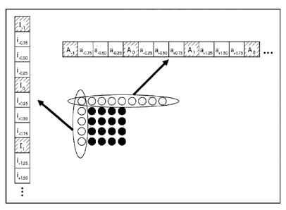
With the example in Fig. 4, positions A indicate the
positions of integer precision pixels, and positions b, c,
and d indicate positions with 1/2 pixel precision, and
positions el, e2, and e3 indicate positions with 1/4 pixel
precision. First, hereafter, Clip() is defined like the
following Expression (1).
[0075]
[Mathematical Expression 1]
Clipl(a)= { 0; if (a<O),
a=otherwise
max pix, if(a>max pm) ===(1)
,
Note that, in the event that the input image has 8-bit
precision, the value of max_pix becomes 255.
[0076]
The pixel values in the positions b and d are generated
like the following Expression (2) using a 6-tap FIR filter.
[Mathematical Expression 2]
F = A_2 - 5 = A_i + 20 = Ao + 20 = Al - 5 = A2 + A3
b, d - Clipl((F + 16) >> 5) . . . (2)
[0077]
CA 02755889 2011-09-16
- 32 -
SlOP0768
The pixel value in the position c is generated like the
following Expression (3) by applying a 6-tap FIR filter in
the horizontal direction and the vertical direction.
[Mathematical Expression 3]
F = b_2 - 5 = b_l + 20 = bo + 20 = bl - 5 = b2 + b3
or
F = d_2 - 5 = d_l + 20 = do + 20 = di - 5 = d2 + d3
c = Clipl ( (F + 512) >> 10) . . . (3)
Note that Clip processing is lastly executed only once
after both of sum-of-products processing in the horizontal
direction and the vertical direction are performed.
[0078]
Positions el through e3 are generated by linear
interpolation as shown in the following Expression (4).
[Mathematical Expression 4]
el = (A + b + 1) >> 1
e2 = (b + d + 1) >> 1
e3 = (b + c + 1) >> 1 . . . (4)
[0079]
With the H.264/AVC system, by the motion prediction and
compensation processing described above with reference to
Figs. 3 through 4 being performed, vast amounts of motion
vector information are generated, and if these are encoded
without change, deterioration in encoding efficiency is
caused. In response to this, with the H.264/AVC system,
CA 02755889
- 33 -
SlOP0768
according to a method shown in Fig. 5, reduction in motion
vector coding information has been realized.
[0080]
Fig. 5 is a diagram for describing a motion vector
information generating method according to the H.264/AVC
system.
[0081]
With the example in Fig. 5, the current block E to be
encoded from now on (e.g., 16 x 16 pixels), and blocks A
through D, which have already been encoded, adjacent to the
current block E are shown.
[0082]
Specifically, the block D is adjacent to the upper left
of the current block E, the block B is adjacent to above the
current block E, the block C is adjacent to the upper right
of the current block E, and the block A is adjacent to the
left of the current block E. Note that the reason why the
blocks A through D are not sectioned is because each of the
blocks represents a block having one structure of 16 x 16
pixels through 4 x 4 pixels described above with reference
to Fig. 2.
[0083]
For example, let us say that motion vector information
as to X (= A, B, C, D, E) is represented with mvx. First,
prediction motion vector information pmvE as to the current
02755889 2011-09-16
- 34 -
SlOP0768
block E is generated like the following Expression (5) by
median prediction using motion vector information regarding
the blocks A, B, and C.
[0084]
pmvE = med ( mvA , mva mvc) . . . (5)
The motion vector information regarding the block C may
not be used (may be unavailable) due to a reason such as the
edge of an image frame, before encoding, or the like. In
this case, the motion vector information regarding the block
D is used instead of the motion vector information regarding
the block C.
[0085]
Data mvdE to be added to the header portion of the
compressed image, serving as the motion vector information
as to the current block E, is generated like the following
Expression (6) using pmvE.
mvdE = mvE - pmvE . . . (6)
[0086]
Note that, in reality, processing is independently
performed as to the components in the horizontal direction
and vertical direction of the motion vector information.
[0087]
In this way, prediction motion vector information is
generated, the data mvdE that is difference between the
prediction motion vector information generated based on
CA 02755889
- 35 -
SlOP0768
correlation with an adjacent block, and the motion vector
information is added to the header portion of the compressed
image as motion vector information, whereby the motion
vector information can be reduced.
[0088]
Here, the prediction and compensation processing with
1/4 pixel precision in the H.264/AVC system described above
with reference to Fig. 4 is executed at the motion
prediction/compensation unit, but with the image encoding
device 51 in Fig. 2, prediction with 1/4 pixel precision is
also performed in intra prediction. This intra prediction
with fractional pixel precision is executed by the intra
prediction unit 74 and adjacent pixel interpolation unit 75,
which will be described next.
[0089]
[Configuration Example of Intra Prediction Unit and
Adjacent Pixel Interpolation Unit]
Fig. 6 is a block diagram illustrating a detailed
configuration example of the intra prediction unit and
adjacent pixel interpolation unit.
[0090]
In the case of the example in Fig. 6, the intra
prediction unit 74 is configured of an adjacent image buffer
81, an optimal mode determining unit 82, an optimal shift
amount determining unit 83, and a prediction image
CA 02755889
- 36 -
SlOP0768
generating unit 84.
[0091]
The adjacent pixel interpolation unit 75 is configured
of a mode determining unit 91, a horizontal direction
interpolation unit 92, and a vertical direction
interpolation unit 93.
[0092]
The adjacent image buffer 81 accumulates an adjacent
pixel of the block to be subjected to intra prediction from
the frame memory 72. In the case of Fig. 6, drawing of the
switch 73 is omitted, but the adjacent pixel is supplied
form the frame memory 72 to the adjacent image buffer 81 via
the switch 73.
[0093]
An image to be subjected to intra prediction read out
from the screen sorting buffer 62 is input to the optimal
mode determining unit 82. The optimal mode determining unit
82 reads out an adjacent pixel corresponding to the block to
be subjected to intra prediction from the adjacent image
buffer 81.
[0094]
The optimal mode determining unit 82 performs intra
prediction processing of all of the intra prediction modes
serving as candidates using the adjacent pixel corresponding
to the image of the block to be subjected to intra
CA 02755889
- 37 -
SlOP0768
prediction to generate a prediction image. The optimal mode
determining unit 82 calculates cost function values as to
the intra prediction modes of which the prediction images
have been generated, and determines the intra prediction
mode of which the calculated cost function value provides
the minimum value to be the optimal intra prediction mode.
The information of the determined prediction mode is
supplied to the mode determining unit 91, optimal shift
amount determining unit 83, and prediction image generating
unit 84. Also, the cost function value corresponding to the
supplied prediction mode is also supplied to the prediction
image generating unit 84.
[0095]
The image to be subjected to intra prediction read out
from the screen sorting buffer 62, and the information of
the prediction mode determined to be the optimal by the
optimal mode determining unit 82 are input to the optimal
shift amount determining unit 83. Also, the adjacent pixel,
which has been subjected to linear interpolation by the
horizontal direction interpolation unit 92 and vertical
direction interpolation unit 93, and the phase of which has
been shifted according to the optimal intra prediction mode
is input to the optimal shift amount determining unit 83.
The optimal shift amount determining unit 83 reads out the
adjacent pixel corresponding to the block to be subjected to
CA 02755889
- 38 -
SlOP0768
intra prediction from the adjacent image buffer 81.
[0096]
The optimal shift amount determining unit 83 uses the
image of the block to be subjected to intra prediction, the
corresponding adjacent pixel, and the pixel value of the
corresponding interpolated adjacent pixel regarding the
prediction mode determined by the optimal mode determining
unit 82 to determine the optimal shift amount. The optimal
shift amount determining unit 83 calculates, for example,
prediction error (residual error) or the like, and
determines a shift amount having the calculated least
prediction error to be the optimal shift amount. The
information of the optimal shift amount determined by the
optimal shift amount determining unit 83 is supplied to the
prediction image generating unit 84.
[0097]
The cost function value corresponding to the prediction
mode information determined by the optimal mode determining
unit 82, and the optimal shift amount information determined
by the optimal shift amount determining unit 83 are input to
the prediction image generating unit 84. The prediction
image generating unit 84 reads out the adjacent pixel
corresponding to the block to be subjected to intra
prediction from the adjacent image buffer 81, and shifts the
phase of the read adjacent pixel in the phase direction
CA 02755889
- 39 -
SlOP0768
according to the prediction mode with the optimal shift
amount.
[0098]
The prediction image generating unit 84 performs intra
prediction in the optimal intra prediction mode determined
by the optimal mode determining unit 82 using the adjacent
pixel of which the phase has been shifted to generate a
prediction image of the block to be processed. The
prediction image generating unit 84 outputs the generated
prediction image and the corresponding cost function value
to the prediction image selecting unit 77.
[0099]
Also, in the event that the prediction image generated
in the optimal intra prediction mode has been selected by
the prediction image selecting unit 77, the prediction image
generating unit 84 supplies the information indicating the
optimal intra prediction mode, and the information of the
shift amount to the lossless encoding unit 66.
[0100]
The mode determining unit 91 outputs the control signal
according to the prediction mode determined by the optimal
mode determining unit 82 to the horizontal direction
interpolation unit 92 and vertical direction interpolation
unit 93. For example, a control signal indicating ON of
interpolation processing is output according to the
CA 02755889
- 40 -
SlOP0768
prediction mode.
[0101]
The horizontal direction interpolation unit 92 and
vertical direction interpolation unit 93 each read out an
adjacent pixel from the adjacent image buffer 81 according
to the control signal from the mode determining unit 91.
The horizontal direction interpolation unit 92 and vertical
direction interpolation unit 93 each shift the phase of the
read adjacent pixel in the horizontal direction and vertical
direction by 6-tap FIR filter and linear interpolation. The
information of the adjacent pixel interpolated by the
horizontal direction interpolation unit 92 and vertical
direction interpolation unit 93 is supplied to the optimal
shift amount determining unit 83.
[0102]
[Description of Encoding Processing of Image Encoding
Device]
Next, the encoding processing of the image encoding
device 51 in Fig. 2 will be described with reference to the
flowchart in Fig. 7.
[0103]
In step S11, the A/D conversion unit 61 converts an
input image from analog to digital. In step S12, the screen
sorting buffer 62 stores the image supplied from the AID
conversion unit 61, and performs sorting from the sequence
CA 02755889
- 41 -
SlOP0768
for displaying the pictures to the sequence for encoding.
[0104]
In step S13, the computing unit 63 computes difference
between an image sorted in step S12 and the prediction image.
The prediction image is supplied to the computing unit 63
from the motion prediction/compensation unit 76 in the event
of performing inter prediction, and from the intra
prediction unit 74 in the event of performing intra
prediction, via the prediction image selecting unit 77.
[0105]
The difference data is smaller in the data amount as
compared to the original image data. Accordingly, the data
amount can be compressed as compared to the case of encoding
the original image without change.
[0106]
In step S14, the orthogonal transform unit 64 subjects
the difference information supplied from the computing unit
63 to orthogonal transform. Specifically, orthogonal
transform, such as discrete cosine transform, Karhunen-Loeve
transform, or the like, is performed, and a transform
coefficient is output. In step S15, the quantization unit
65 quantizes the transform coefficient. At the time of this
quantization, a rate is controlled such that later-described
processing in step S25 will be described.
[0107]
CA 02755889
- 42 -
SlOP0768
The difference information thus quantized is locally
decoded as follows. Specifically, in step S16, the inverse
quantization unit 68 subjects the transform coefficient
quantized by the quantization unit 65 to inverse
quantization using a property corresponding to the property
of the quantization unit 65. In step S17, the inverse
orthogonal transform unit 69 subjects the transform
coefficient subjected to inverse quantization by the inverse
quantization unit 68 to inverse orthogonal transform using a
property corresponding to the property of the orthogonal
transform unit 64.
[0108]
In step S18, the computing unit 70 adds the prediction
image input via the prediction image selecting unit 77 to
the locally decoded difference information, and generates a
locally decoded image (the image corresponding to the input
to the computing unit 63). In step S19, the deblocking
filter 71 subjects the image output from the computing unit
70 to filtering. Thus, block distortion is removed. In step
S20, the frame memory 72 stores the image subjected to
filtering. Note that an image not subjected to filtering
processing by the deblocking filter 71 is also supplied from
the computing unit 70 to the frame memory 72 for storing.
[0109]
In step S21, the intra prediction unit 74 and motion
02755889 2011-09-16
- 43 -
SlOP0768
prediction/compensation unit 76 each perform image
prediction processing. Specifically, in step S21, the intra
prediction unit 74 performs intra prediction processing in
the intra prediction mode. The motion
prediction/compensation unit 76 performs motion prediction
and compensation processing in the inter prediction mode.
[0110]
The details of the prediction processing in step S21
will be described later with reference to Fig. 8, but
according to this processing, the prediction processes in
all of the intra prediction modes serving as candidates are
performed, and the cost function values in all of the
prediction modes serving as candidates are calculated. The
optimal intra prediction mode is selected based on the
calculated cost function values, and the prediction image
generated by the intra prediction in the optimal intra
prediction mode, and the cost function value thereof are
supplied to the prediction image selecting unit 77.
[0111]
Specifically, at this time, the intra prediction unit
74 supplies the prediction image generated by intra
prediction using the adjacent pixel of which the phase has
been shifted in the shift direction according to the optimal
intra prediction mode by 6-tap FIR filter and linear
interpolation with the optimal shift amount, to the
CA 02755889
- 44 -
SlOP0766
prediction image selecting unit 77. Note that the cost
function value regarding the optimal intra prediction mode
is also supplied to the prediction image selecting unit 77
along with the prediction image.
[0112]
On the other hand, based on the calculated cost
function values, the optimal inter prediction mode is
determined out of the inter prediction modes, and the
prediction image generated in the optimal inter prediction
mode, and the cost function value thereof are supplied to
the prediction image selecting unit 77.
[0113]
In step S22, the prediction image selecting unit 77
determines one of the optimal intra prediction mode and the
optimal inter prediction mode to be the optimal prediction
mode based on the cost function values output from the intra
prediction unit 74 and the motion prediction/compensation
unit 76. The prediction image selecting unit 77 then
selects the prediction image in the determined optimal
prediction mode, and supplies to the computing units 63 and
70. This prediction image is, as described above, used for
calculations in steps S13 and S18.
[0114]
Note that the selection information of this prediction
image is supplied to the intra prediction unit 74 or motion
CA 02755889
- 45 -
SlOP0768
prediction/compensation unit 76. In the event that the
prediction image in the optimal intra prediction mode has
been selected, the intra prediction unit 74 supplies
information indicating the optimal intra prediction mode
(i.e., intra prediction mode information) and information of
the shift amount determined to be the optimal, to the
lossless encoding unit 66.
[0115]
In the event that the prediction image in the optimal
inter prediction mode has been selected, the motion
prediction/compensation unit 76 outputs information
indicating the optimal inter prediction mode, and according
to need, information according to the optimal inter
prediction mode to the lossless encoding unit 66. Examples
of the information according to the optimal inter prediction
mode include motion vector information, flag information,
and reference frame information. Specifically, in the event
that the prediction image according to the inter prediction
mode has been selected as the optimal inter prediction mode,
the motion prediction/compensation unit 76 outputs the inter
prediction mode information, motion vector information, and
reference frame information to the lossless encoding unit 66.
[0116]
In step S23, the lossless encoding unit 66 encodes the
quantized transform coefficient output from the quantization
CA 02755889
- 46 -
SlOP0768
unit 65. Specifically, the difference image is subjected to
lossless encoding such as variable length coding, arithmetic
coding, or the like, and compressed. At this time, the
intra prediction mode information from the intra prediction
unit 74, or the information according to the optimal inter
prediction mode from the motion prediction/compensation unit
76, and so forth input to the lossless encoding unit 66 in
step S22 described above are also encoded, and added to the
header information.
[0117]
In step S24, the accumulating buffer 67 accumulates the
difference image as the compressed image. The compressed
image accumulated in the accumulating buffer 67 is read out
as appropriate, and transmitted to the decoding side via the
transmission path.
[0118]
In step S25, the rate control unit 78 controls the rate
of the quantization operation of the quantization unit 65
based on the compressed image accumulated in the
accumulating buffer 67 so as not to cause overflow or
under flow.
[0119]
[Description of Prediction Processing]
Next, the prediction processing in step S21 in Fig. 7
will be described with reference to the flowchart in Fig. 8.
02755889 2011-09-16
- 47 -
SlOP0768
[0120]
In the event that the image to be processed, supplied
from the screen sorting buffer 62, is an image in a block to
be subjected to intra processing, the decoded image to be
referenced is read out from the frame memory 72, and
supplied to the intra prediction unit 74 via the switch 73.
[0121]
In step S31, the intra prediction unit 74 uses the
supplied image to subject pixels of the block to be
processed to intra prediction in all of the intra prediction
modes serving as candidates. Note that pixels not subjected
to deblocking filtering by the deblocking filter 71 are used
as the decoded pixels to be referenced.
[0122]
The details of the intra prediction processing in step
S31 will be described later with reference to Fig. 20, but
according to this processing, intra prediction is performed
using all of the intra prediction modes serving as
candidates. A cost function value is calculated as to all
of the intra prediction modes serving as candidates, and the
optimal intra prediction mode is determined based on the
calculated cost function values.
[0123]
Subsequently, according to 6-tap FIR filter and linear
interpolation, the phase of an adjacent pixel is shifted
02755889 2011-09-16
- 48 -
SlOP0768
with the optimal shift amount in the shift direction
according to the determined optimal intra prediction mode.
A prediction image is generated by intra prediction in the
optimal intra prediction mode using the adjacent pixel of
which the phase has been shifted. The generated prediction
image and the cost function value of the optimal intra
prediction mode are supplied to the prediction image
selecting unit 77.
[0124]
In the event that the image to be processed supplied
from the screen sorting buffer 62 is an image to be
subjected to inter processing, the image to be referenced is
read out from the frame memory 72, and supplied to the
motion prediction/compensation unit 76 via the switch 73.
In step S32, based on these images, the motion
prediction/compensation unit 76 performs inter motion
prediction processing. That is to say, the motion
prediction/compensation unit 76 references the image
supplied from the frame memory 72 to perform the motion
prediction processing in all of the inter prediction modes
serving as candidates.
[0125]
The details of the inter motion prediction processing
in step S32 will be described later with reference to Fig.
22, but according to this processing, the motion prediction
02755889 2011-09-16
- 49 -
SlOP0768
processing in all of the inter prediction modes serving as
candidates is performed, and a cost function value as to all
of the inter prediction modes serving as candidates is
calculated.
[0126]
In step S33, the motion prediction/compensation unit 76
compares the cost function values as to the inter prediction
modes calculated in step S32, and determines the prediction
mode that provides the minimum value, to be the optimal
inter prediction mode. The motion prediction/compensation
unit 76 supplies the prediction image generated in the
optimal inter prediction mode, and the cost function value
thereof to the prediction image selecting unit 77.
[0127]
[Description of Intra Prediction Processing According
to H.264/AVC system]
Next, the intra prediction modes determined by the
H.264/AVC system will be described.
[0128]
First, the intra-prediction modes as to luminance
signals will be described. With the intra prediction modes
for luminance signals, three systems of an intra 4 x 4
prediction mode, an intra 8 x 8 prediction mode, and an
intra 16 x 16 prediction mode are determined. These are
modes for determining block units, and are set for each
02755889 2011-09-16
- 50 -
SlOP0768
macro block. Also, an intra prediction mode may be set to
color difference signals independently from luminance
signals for each macro block.
[0129]
Further, in the event of the intra 4 x 4 prediction
mode, one prediction mode can be set out of the nine kinds
of prediction modes for each 4 x 4-piexl current block. In
the event of the intra 8 x 8 prediction mode, one prediction
mode can be set out of the nine kinds of prediction modes
for each 8 x 8-piexl current block. Also, in the event of
the intra 16 x 16 prediction mode, one prediction mode can
be set to a 16 x 16-pixel current macro block out of the
four kinds of prediction modes.
[0130]
Note that, hereafter, the intra 4 x 4 prediction mode,
intra 8 x 8 prediction mode, and intra 16 x 16 prediction
mode will also be referred to as 4 x 4-pixel intra
prediction mode, 8 x 8-pixel intra prediction mode, and 16 x
16-pixel intra prediction mode as appropriate, respectively.
[0131]
With the example in Fig. 9, numerals -1 through 25
appended to the blocks represent the bit stream sequence
(processing sequence on the decoding side) of the blocks
thereof. Note that, with regard to luminance signals, a
macro block is divided into 4 x 4 pixels, and DOT of 4 x 4
CA 02755889
- 51 -
SlOP0768
pixels is performed. Only in the event of the intra 16 x 16
prediction mode, as shown in a block of -1, the DC
components of the blocks are collected, a 4 x 4 matrix is
generated, and this is further subjected to orthogonal
transform.
[0132]
On the other hand, with regard to color difference
signals, after a macro block is divided into 4 x 4 pixels,
and DCT of 4 x 4 pixels is performed, as shown in the blocks
16 and 17, the DC components of the blocks are collected, a
2 x 2 matrix is generated, and this is further subjected to
orthogonal transform.
[0133]
Note that, with regard to the intra 8 x 8 prediction
mode, this may be applied to only a case where the current
macro block is subjected to 8 x 8 orthogonal transform with
a high profile or a profile beyond this.
[0134]
Fig. 10 and Fig. 11 are diagrams showing nine kinds of
4 x 4-pixel intra-prediction modes (Intra 4x4 pred mode) for
_ _
luminance signals. The eight kinds of modes other than the
mode 2 showing average value (DC) prediction correspond to
directions indicated with numbers 0, 1, 3 through 8 in Fig.
8, respectively.
[0135]
CA 02755889
- 52 -
SlOP0768
The nine kinds of intra 4x4 pred mode will be described
_ _
with reference to Fig. 12. With the example in Fig. 12,
pixels a through p represent the pixels of the block to be
subjected to intra-processing, and pixel values A through M
represent the pixel values of pixels belonging to an
adjacent block. Specifically, the pixels a through p are an
image to be processed read out from the screen sorting
buffer 62, and the pixel values A through M are the pixel
values of a decoded image to be read out from the frame
memory 72 and referenced.
[0136]
In the event of the intra-prediction modes shown in Fig.
and Fig. 11, the prediction pixel values of the pixels a
through p are generated as follows using the pixel values A
through M of the pixels belonging to an adjacent pixel.
Here, that a pixel value is "available" represents that the
pixel value is available without a reason such that the
pixel is positioned in the edge of the image frame, or has
not been encoded yet. On the other hand, that a pixel value
is "unavailable" represents that the pixel value is
unavailable due to a reason such that the pixel is
positioned in the edge of the image frame, or has not been
encoded yet.
[0137]
The mode 0 is a Vertical Prediction mode (vertical
CA 02755889
- 53 -
SlOP0768
prediction mode), and is applied to only a case where the
pixel values A through D are "available". In this case, the
prediction pixel values of the pixels a through p are
generated like the following Expression (7).
Prediction pixel values of pixels a, e, i, and m = A
Prediction pixel values of pixels b, f, j, and n = B
Prediction pixel values of pixels c, g, k, and o = C
Prediction pixel values of pixels d, h, 1, and p = D . . .
(7)
[0138]
The mode 1 is a Horizontal Prediction mode (horizontal
prediction mode), and is applied to only a case where the
pixel values I through L are "available". In this case, the
prediction pixel values of the pixels a through p are
generated like the following Expression (8).
Prediction pixel values of pixels a, b, c, and d = I
Prediction pixel values of pixels e, f, g, and h = J
Prediction pixel values of pixels i, j, k, and 1 = K
Prediction pixel values of pixels m, n, o, and p = L . . .
(8)
[0139]
The mode 2 is a DC Prediction mode, and the prediction
pixel value is generated like Expression (9) when the pixel
values A, B, C, D, I, J, K, and L are all "available".
(A+B+C+D+I+J+K+L+ 4)>> 3 ... (9)
02755889 2011-09-16
- 54 -
SlOP0768
[0140]
Also, when the pixel values A, B, C, and D are all
"unavailable", the prediction pixel value is generated like
Expression (10).
(I + J + K + L + 2) >> 2 . . . (10)
[0141]
Also, when the pixel values I, J, K, and L are all
"unavailable", the prediction pixel value is generated like
Expression (11).
(A + B + C + D + 2) >> 2 . . . (11)
[0142]
Note that, when the pixel values A, B, C, D, I, J, K,
and L are all "unavailable", 128 is employed as the
prediction pixel value.
[0143]
The mode 3 is a Diagonal_Down_Left Prediction mode, and
is applied to only a case where the pixel values A, B, C, D,
I, J, K, L, and M are "available". In this case, the
prediction pixel values of the pixels a through p are
generated like the following Expression (12).
Prediction pixel value of pixel a = (A + 2B + C + 2) >> 2
Prediction pixel values of pixels b and e = (B + 2C + D + 2)
>> 2
Prediction pixel values of pixels c, f, and i = (C + 2D + E
+ 2) >> 2
02755889 2011-09-16
- 55 -
SlOP0768
Prediction pixel values of pixels d, g, j, and m = (D + 2E +
F + 2) >> 2
Prediction pixel values of pixels h, k, and n = (E + 2F + G
+ 2) >> 2
Prediction pixel values of pixels 1 and o = (F + 2G + H + 2)
>> 2
Prediction pixel value of pixel p = (G + 3H + 2) >> 2 . . .
(12)
[0144]
The mode 4 is a Diagonal_Down_Right Prediction mode,
and is applied to only a case where the pixel values A, B, C,
D, I, J, K, L, and M are "available". In this case, the
prediction pixel values of the pixels a through p are
generated like the following Expression (13).
Prediction pixel value of pixel m = (J + 2K + L + 2) >> 2
Prediction pixel values of pixels i and n = (I + 2J + K + 2)
>> 2
Prediction pixel values of pixels e, j, and o = (M + 21 + J
+ 2) >> 2
Prediction pixel values of pixels a, f, k, and p = (A + 2M +
I + 2) >> 2
Prediction pixel values of pixels b, g, and 1 = (M + 2A + B
+ 2) >> 2
Prediction pixel values of pixels c and h = (A + 2B + C + 2)
>> 2
02755889 2011-09-16
- 56 -
SlOP0768
Prediction pixel value of pixel d = (B + 20 + D + 2) >>
2 . . . (13)
[0145]
The mode 5 is a Diagonal_Vertical_Right Prediction mode,
and is applied to only a case where the pixel values A, B, C,
D, I, J, K, L, and M are "available". In this case, the
prediction pixel values of the pixels a through p are
generated like the following Expression (14).
Prediction pixel values of pixels a and j = (M + A + 1) >> 1
Prediction pixel values of pixels b and k = (A + B + 1) >> 1
Prediction pixel values of pixels c and 1 = (B + C + 1) >> 1
Prediction pixel value of pixel d = (C + D + 1) >> 1
Prediction pixel values of pixels e and n = (1 + 2M + A + 2)
>> 2
Prediction pixel values of pixels f and o = (M + 2A + B + 2)
>> 2
Prediction pixel values of pixels g and p = (A + 2B + C + 2)
>> 2
Prediction pixel value of pixel h = (B + 20 + D + 2) >> 2
Prediction pixel value of pixel i = (M + 21 + J + 2) >> 2
Prediction pixel value of pixel m = (I + 2J + K + 2) >>
2 . . . (14)
[0146]
The mode 6 is a Horizontal Down Prediction mode, and is
applied to only a case where the pixel values A, B, C, D, I,
CA 02755889
- 57 -
SlOP0768
J, K, L, and M are "available". In this case, the
prediction pixel values of the pixels a through p are
generated like the following Expression (15).
Prediction pixel values of pixels a and g = (M + I + 1) >> 1
Prediction pixel values of pixels b and h = (I + 2M + A + 2)
>> 2
Prediction pixel value of pixel c = (M + 2A + B + 2) >> 2
Prediction pixel value of pixel d - (A + 2B + C + 2) >> 2
Prediction pixel values of pixels e and k = (I + J + 1) >> 1
Prediction pixel values of pixels f and 1 = (M + 21 + J + 2)
>> 2
Prediction pixel values of pixels i and o = (J + K + 1) >> 1
Prediction pixel values of pixels j and p = (I + 2J + K + 2)
>> 2
Prediction pixel value of pixel m = (K + L + 1) >> 1
Prediction pixel value of pixel n = (J + 2K + L + 2) >>
2 . . . (15)
[0147]
The mode 7 is a Vertical Left Prediction mode, and is
applied to only a case where the pixel values A, B, C, D, I,
J, K, L, and M are "available". In this case, the
prediction pixel values of the pixels a through p are
generated like the following Expression (16).
Prediction pixel value of pixel a = (A + B + 1) >> 1
Prediction pixel values of pixels b and i = (B + C + 1) >> 1
ud)275Emm
- 58 -
SlOP0768
Prediction pixel values of pixels c and j = (C + D + 1) >> 1
Prediction pixel values of pixels d and k = (D + E + 1) >> 1
Prediction pixel value of pixel 1 = (E + F + 1) >> 1
Prediction pixel value of pixel e = (A + 2B + C + 2) >> 2
Prediction pixel values of pixels f and m = (B + 2C + D + 2)
>> 2
Prediction pixel values of pixels g and n = (C + 2D + E + 2)
>> 2
Prediction pixel values of pixels h and o = (D + 2E + F + 2)
>> 2
Prediction pixel value of pixel p = (E + 2F + G + 2) >>
2 . . . (16)
[0148]
The mode 8 is a Horizontal_Up Prediction mode, and is
applied to only a case where the pixel values A, B, C, D, I,
J, K, L, and M are "available". In this case, the
prediction pixel values of the pixels a through p are
generated like the following Expression (17).
Prediction pixel value of pixel a = (I + J + 1) >> 1
Prediction pixel value of pixel b = (I + 2J + K + 2) >> 2
Prediction pixel values of pixels c and e = (J + K + 1) >> 1
Prediction pixel values of pixels d and f = (J + 2K + L + 2)
>> 2
Prediction pixel values of pixels g and i = (K + L + 1) >> 1
Prediction pixel values of pixels h and j = (K + 3L + 2) >>
02755889 2011-09-16
- 59 -
S10P0768
2
Prediction pixel values of pixels k, 1, m, n, o, and p =
L . . . (17)
[0149]
Next, the encoding system of the 4 x 4-pixel intra-
prediction mode (Intra_4x4_pred_mode) for luminance signals
will be described with reference to Fig. 13. With the
example in Fig. 13, the current block C to be encoded, which
is made up of 4 x 4 pixels, is shown, and a block A and a
block B, which are adjacent to the current block C and are
made up of 4 x 4 pixels, are shown.
[0150]
In this case, it can be conceived that the
Intra 4x4 pred mode in the current block C, and the
_ _
Intra 4x4 pred mode in the block A and block B have high
_ _
correlation. Encoding processing is performed as follows
using this correlation, whereby higher encoding efficiency
can be realized.
[0151]
Specifically, with the example in Fig. 13, the
Intra 4x4 pred mode in the block A and block B are taken as
_ _
Intra 4x4 pred modeA and Intra 4x4 pred modeB respectively,
_ _ _ _
and MostProbableMode is defined as the following Expression
(18).
MostProbableMode - Min(Intra_4x4_pred_modeA,
CA 02755889
- 60 -
S10P0768
Intra 4x4 pred modeB) . . . (18)
_ _
[0152]
That is to say, of the block A and block B, one to
which a smaller mode number is assigned is taken as
MostProbableMode.
[0153]
Two values called as
prev_intra4x4_pred_mode_flag[luma4x4B1k1dx] are defined
within a bit stream as parameters as to the current block C,
and decoding processing is performed by processing based on
the pseudo-code shown in the following Expression (19),
whereby the values of Intra_4x4_pred_mode and
Intra4x4PredMode[luma4x4B1k1dx] as to the current block C
can be obtained.
[0154]
if(prev_intra4x4_pred_mode_flag[luma4x4B1k1dx])
Intra4x4PredMode[luma4x4B1k1dx] = MostProbableMode
else
if(rem_intra4x4_pred_mode[luma4x4B1k1dx] <
MostProbableMode)
Intra4x4PredMode[luma4x4B1k1dx] =
rem intra4x4 pred mode[luma4x4B1k1dx]
else
Intra4x4PredMode[luma4x4B1k1dx] =
rem intra4x4 pred mode[luma4x4B1k1dx] + 1 . . . (19)
CA 02755889
- 61 -
SlOP0768
[0155]
Next, the 16 x 16-pixel intra prediction mode will be
described. Fig. 14 and Fig. 15 are diagrams showing the
four kinds of the 16 x 16-pixel intra prediction modes for
luminance signals (Intra_16x16_pred_mode).
[0156]
The four kinds of intra prediction modes will be
described wither reference to Fig. 16. With the example in
Fig. 16, the current macro block A to be subjected to intra-
processing is shown, and P(x, y); x, y = -1, 0, 15
represents the pixel value of a pixel adjacent to the
current macro block A.
[0157]
The mode 0 is a Vertical Prediction mode, and is
applied only when P(x, -1); x, y = -1, 0, 15 is
"available". In this case, the prediction pixel value
Pred(x, y) of each pixel of the current macro block A is
generated like the following Expression (20).
Pred(x, y) = P(x, -1); x, y = 0, 15 . . . (20)
[0158]
The mode 1 is a Horizontal Prediction mode, and is
applied only when P(-1, y); x, y = -1, 0, 15 is
"available". In this case, the prediction pixel value
Pred(x, y) of each pixel of the current macro block A is
generated like the following Expression (21).
CA 02755889 2011-09-16
- 62 -
SlOP0768
Pred(x, y) = P(-1, y); x, y = 0, 15 . . . (21)
[0159]
The mode 2 is a DC Prediction mode, and in the event
that all of P(x, -1) and P(-1, y); x, y = -1, 0, 15 are
"available", the prediction pixel value Pred(x, y) of each
pixel of the current macro block A is generated like the
following Expression (22).
[Mathematical expression 5]
15 15
Pred(x, y) =[P(x', ¨1)+1 P (-1,y')+161>> 5
x-o
with x, y = 0,===,15 "'(22)
[0160]
Also, in the event that P(x, -1); x, y = -1, 0, 15
is "unavailable", the prediction pixel value Pred(x, y) of
each pixel of the current macro block A is generated like
the following Expression (23).
[Mathematical expression 6]
Pred(x, y) = [Ep( --1,37')+8] 4 with x, y = 0,- = -,15 -(23)
[0161]
In the event that P(-1, y); x, y = -1, 0, 15 is
"unavailable", the prediction pixel value Pred(x, y) of each
pixel of the current macro block A is generated like the
following Expression (24).
[Mathematical expression 7]
CA 02755889 2011-09-16
- 63 -
SlOP0768
Pred(X5 y) = [EP( Xt, -0+81 4 with x, y = -,15
"(24)
[0162]
In the event that all of P(x, -1) and P(-1, y); x, y =
-1, 0, 15 are "unavailable", 128 is employed as the
prediction pixel value.
[0163]
The mode 3 is a Plane Prediction mode, and is applied
only when all of P(x, -1) and P(-1, y); x, y = -1, 0, 15
are "available". In this case, the prediction pixel value
Pred(x, y) of each pixel of the current macro block A is
generated like the following Expression (25).
[Mathematical expression 8]
Pred(x,y) = Clipl((a+b = (x-7)+c = (y-7)+16) >>5)
a= 16 = (P(-1,15)+P(15,-1))
b = (5 = H+32)>>6
c = (5 = V+32) 6
8
H =Ex = (P(7+x,-1)¨P(7¨x,-1))
,-1
8
V =Ey = (P(-1,7+y)¨P(-1,7¨y)) -(25)
y-1
[0164]
Next, the intra prediction modes as to color difference
signals will be described. Fig. 17 is a diagram showing the
four kinds of intra prediction modes for color difference
02755889 2011-09-16
- 64 -
SlOP0768
signals (Intra_chroma_pred_mode). The intra prediction
modes for color difference signals may be set independently
from the intra prediction modes for luminance signals. The
intra prediction modes as to color difference signals
conform to the above-mentioned 16 x 16-pixel intra
prediction modes for luminance signals.
[0165]
However, the 16 x 16-pixel intra prediction modes for
luminance signals take a 16 x 16-pixel block as an object,
but on the other hand, the intra prediction modes as to
color difference signals take an 8 x 8-pixel block as an
object. Further, as shown in the above-mentioned Fig. 14
and Fig. 17, mode numbers between both do not correspond.
[0166]
Now, let us conform to the definitions of the pixel
values of the current block A in the 16 x 16-pixel intra
prediction mode, and an adjacent pixel value. For example,
let us say that the pixel value of a pixel adjacent to the
current macro block A (8 x 8 pixels in the event of color
difference) to be subjected to intra processing is taken as
P(x, y); x, y = -1, 0, ..., 7.
[0167]
The mode 0 is a DC Prediction mode, and in the event
that all of P(x, -1) and P(-1, y); x, y = -1, 0, ..., 7 are
"available", the prediction pixel value Pred(x, y) of each
CA 02755889 2011-09-16
- 65 -
SlOP0768
pixel of the current macro block A is generated like the
following Expression (26).
[Mathematical expression 9]
7
Pred(x, y) = (I(P(-1,n)+P(n,-1)))+8) >> 4
=
with x, y = 0,===,7 (26)
[0168]
Also, in the event that P(-1, y); x, y = -1, 0, 7 is
"unavailable", the prediction pixel value Pred(x, y) of each
pixel of the current macro block A is generated like the
following Expression (27).
[Mathematical expression 10]
7
Pred(x, y) =RE P(n,-1))+4]>>3 with x, y = -.(27)
n -0
[0169]
Also, in the event that P(x, -1); x, y = -1, 0, 7 is
"unavailable", the prediction pixel value Pred(x, y) of each
pixel of the current macro block A is generated like the
following Expression (28).
[Mathematical expression 11]
7
Pred(x, y) =[(E P(- 1, n))+4]>>3 with x, y = 0,===,7 -.(28)
[0170]
The mode 1 is a Horizontal Prediction mode, and is
applied only when P(-1, y); x, y = -1, 0, 7 is
02755889 2011-09-16
- 66 -
SlOP0768
"available". In this case, the prediction pixel value
Pred(x, y) of each pixel of the current macro block A is
generated like the following Expression (29).
Pred(x, y) = P(-1, y); x, y = 0, ..., 7 . . . (29)
[0171]
The mode 2 is a Vertical Prediction mode, and is
applied only when P(x, -1); x, y = -1, 0, 7 is
"available". In this case, the prediction pixel value
Pred(x, y) of each pixel of the current macro block A is
generated like the following Expression (30).
Pred(x, y) = P(x, -1); x, y = 0, 7 . . . (30)
[0172]
The mode 3 is a Plane Prediction mode, and is applied
only when P(x, -1) and P(-1, y); x, y = -1, 0, 7 are
"available". In this case, the prediction pixel value
Pred(x, y) of each pixel of the current macro block A is
generated like the following Expression (31).
[Mathematical expression 12]
CA 02755889 2011-09-16
- 67 -
SlOP0768
Pred(x,y) = Clipl(a+b = (x-3)+c = (y-3)+16) >>5,x,y =0,...,7
a= 16 = (P(-1,7)+P(7,-1))
b = (17 = H+16)>>5
c = (17 = V+ 16) >>5
4
H. =Z x = [P(3 +x,-1)-P(3 -x,-1
4
V = y = FP(-1,3+y)-P(-i,3-y)] -=(31)
[0173]
As described above, the intra-prediction modes for
luminance signals include the nine kinds of prediction modes
of 4 x 4-pixel and 8 x 8-pixel block units, and the four
kinds of prediction modes of 16 x 16-pixel macro block units.
The modes of these block units are set for each macro block
unit. The intra prediction modes for color difference
signals include the four kinds of prediction modes of 8 x 8-
pixel block units. The intra prediction modes for color
difference signals may be set independently from the intra
prediction modes for luminance signals.
[0174]
Also, with regard to the 4 x 4-pixel intra prediction
modes (intra 4 x 4 prediction modes), and the 8 x 8-pixel
intra prediction modes (intra 8 x 8 prediction modes) for
luminance signals, one intra prediction mode is set for each
4 x 4-pixel and 8 x 8-pixel luminance signal block. With
CA 02755889
- 68 -
SlOP0768
regard to the 16 x 16-pixel intra prediction mode (intra 16
x 16 prediction mode) for luminance signals and the intra
prediction modes for color difference signals, one
prediction mode is set as to one macro block.
[0175]
Note that the kinds of prediction modes correspond to
directions indicated with the above-mentioned numbers 0, 1,
3 through 8 in Fig. 1. The prediction mode 2 is average
value prediction.
[0176]
As described above, the intra prediction according to
the H.264/AVC system is performed with integer pixel
precision. On the other hand, with the image encoding
device 51, intra prediction with fraction pixel precision is
performed.
[0177]
[Operation of Intra Prediction with Fraction Pixel
Precision]
Next, operation for realizing intra prediction with
fraction pixel precision will be described with reference to
Fig. 18. Note that the example in Fig. 18 illustrates an
example in the event the current block has 4 x 4 pixels.
[0178]
In the case of the example in Fig. 18, solid circles
represent the pixels of the current block to be subjected to
CA 02755889 2011-09-16
- 69 -
SlOP0768
intra prediction, and white circles represent adjacent
pixels adjacent to the current block. Further, in details,
of the adjacent pixels that are the white circles, the upper
left adjacent pixel adjacent to the upper left potion of the
current block is A_1 and also 1_1, and this pixel is
equivalent to a pixel of which the pixel value is M in Fig.
12. Of the adjacent pixels that are white circles, the
upper adjacent pixels adjacent to the upper portion of the
current block are Ao, Al, A2, and so on, and these pixels are
equivalent to pixels of which the pixel values are A through
H in Fig. 12. Of the adjacent pixels that are white circles,
the left adjacent pixels adjacent to the left portion of the
current block are Io, II, 12, and so on, and these pixels are
equivalent to pixels of which the pixel values are I through
L in Fig. 12.
[0179]
Also, a_0.5, a+0.5, and so on, and i+0.5, and so on
shown between the adjacent pixels represent pixels with 1/2
pixel precision. Further, a_0.75, a_0.25, a+0.25, a+0.75, and SO
on, and i_0.75, i+0.75, and so on shown between the
pixels a_0.5, .3+0.5, and so on, and 1+0.5, and so on
represent pixels with 1/4 pixel precision.
[0180]
First, as a first operation, with the intra prediction
unit 74, intra prediction is performed as to the intra
CA02755M9201109M
- 70 -
SlOP0768
prediction modes using the pixel values A through M shown in
Fig. 12, and the optimal intra prediction is determined out
of the intra prediction modes. In the event that the
current block is 4 x 4, this optimal intra prediction mode
is one of the nine prediction modes in Fig. 10 or Fig. 11.
[0181]
For example, let us say that the mode 0 (Vertical
Prediction mode) has been selected as the optimal intra
prediction mode. At this time, adjacent pixels used for
prediction of the current block are the pixels Ao, Al, A2,
and A3 in Fig. 18 of which the pixel values are pixel values
A through D in Fig. 12.
[0182]
As a second operation, with the adjacent pixel
interpolation unit 75, according to the 6-tap FIR filter
according to the H.264/AVC system described above with
reference to Fig. 4, pixels a_0.5, a+0.5, and so on with 1/2
pixel precision in Fig. 18 are generated. That is to say,
the pixel a_0.5 is shown with the following Expression (32).
a_0.5= (A..2 + 20*A0+ 20*A1-5*A1+ A2+ 16) >> 5 . . .
(32)
This may be applied to other pixels a+0.5, a+1.5, and so forth
with 1/2 pixel precision.
[0183]
As a third operation, with the adjacent pixel
CA 02755889 2011-09-16
- 71 -
SlOP0768
interpolation unit 75, pixels a-0.75r a-0.25r a+0.25r and a+0.75
with 1/4 pixel precision in Fig. 18 are generated from
pixels Ao, Al, A2, A3, and pixels a_0.5, a,0.5, and so forth by
linear interpolation. Specifically, the pixel a+0.25 is
indicated by the following Expression (33).
[0184]
a_0.5 = Ao + a+0.5 + 1) >> 2 . . . (33)
This may be applied to other pixels with 1/4 pixel precision.
[0185]
As a fourth operation, with the intra prediction unit
74, in the case of the mode 0, values -0.75, -0.50, -0.25,
+0.25, +0.50, and +0.75 that are phase differences between
an integer pixel and each of the fractional pixel precisions
are taken as candidates in the shift amount in the
horizontal direction, and the optimal shift amount is
determined.
[0186]
For example, in the event that the shift amount is
+0.25, intra prediction is performed using the pixel values
of pixels a+0.25r a+1.25r a+2.25r and a+3.25 instead of the pixel
values of the pixels Ao, AI, A2, and A3.
[0187]
In this way, the optimal shift amount is determined as
to the optimal intra prediction mode selected in the first
operation. For example, there may be a case where the shift
CA 02755889 2011-09-16
- 72 -
SlOP0768
amount is 0 is determined to be the optimal, and the pixel
value of an integer pixel is used.
[0188]
Note that, of the nine prediction modes shown in Fig.
or Fig. 11, with regard to the mode 2 (DC prediction
mode), average value processing is performed. Accordingly,
even when performing shift, this does not directly get
involved with improvement in encoding efficiency, and
accordingly, the above-mentioned operation is inhibited and
not performed.
[0189]
With regard to the mode 0 (Vertical Prediction mode),
mode 3 (Diagonal_Down_Left Prediction mode), or mode 7
(Vertical Left Prediction mode), shift only with the upper
adjacent pixels Ao, Al, A2, and so on in Fig. 18 serves as a
candidate.
[0190]
With regard to the mode 1 (Horizontal Prediction mode)
or mode 8 (Horizontal_Up Prediction mode), shift only with
the left adjacent pixels I , I, 12, and so on in Fig. 18
serves as a candidate.
[0191]
With regard to the other modes (modes 4 through 6),
shift has to be taken into consideration regarding both of
the upper adjacent pixels and left adjacent pixels.
CA 02755889
- 73 -
SlOP0768
[0192]
Also, with regard to the upper adjacent pixels, only
the shift amount in the horizontal direction is determined,
and with regard to the left adjacent pixels, only the shift
amount in the vertical direction is determined.
[0193]
The above-mentioned first through fourth operations are
preformed to determine the optimal shift amount, whereby the
choices of pixel values used in the intra prediction mode
can be increased, and further optimal intra prediction can
be performed. Thus, encoding efficiency in intra prediction
can further be improved.
[0194]
Also, with the H.264/AVC system, as described above
with reference to Fig. 4, the circuit of a 6-tap FIR filter
only used for inter motion prediction compensation can also
effectively be used for intra prediction. Thus, efficiency
can be improved without increasing the circuit.
[0195]
Further, there can be performed intra prediction with
further finer resolution than 22.5 degrees that is
resolution for intra prediction determined in the H.264/AVC
system.
[0196]
[Advantageous Effect Example of Intra Prediction with
CA02755M9201109M
- 74 -
SlOP0768
Fractional Pixel Precision]
With the example in Fig. 19, dotted lines represent the
directions of the prediction modes of intra prediction
according to the H.264/AVC system described above with
reference to Fig. 1. Numbers appended with the dotted lines
correspond to the numbers of the nine prediction modes shown
in Fig. 10 or Fig. 11, respectively. Note that the mode 2
is average value prediction, and accordingly, the number
thereof is not shown.
[0197]
With the H.264/AVC system, intra prediction can be
performed only with resolution of 22.5 degrees shown in
dotted lines. On the other hand, with the image encoding
device 51, intra prediction with fractional pixel precision
is performed, intra prediction with further finer resolution
than 22.5 degrees as represented with a thick line. Thus,
in particular, encoding efficiency as to texture having an
oblique edge can be improved.
[0198]
[Description of Intra Prediction Processing]
Next, intra prediction processing serving as the above-
mentioned operations will be described with reference to the
flowchart in Fig. 20. Note that this intra prediction
processing is the intra prediction processing in step S31 in
Fig. 8, and with the example in Fig. 20, description will be
CA 02755889
- 75 -
SlOP0768
made a case of luminance signals as an example.
[0199]
In step S41, the optimal mode determining unit 82
performs intra prediction as to the intra prediction modes
of 4 x 4 pixels, 8 x 8 pixels, and 16 x 16 pixels.
[0200]
As described above, with the intra 4 x 4 prediction
modes and the intra 8 x 8 prediction modes, there are
provided nine kinds of prediction modes, and one prediction
mode may be defined for each block, respectively. With
regard to the intra 16 x 16 prediction mode, and the intra
prediction mode for color difference signals, one prediction
mode may be defined as to one macro block.
[0201]
The optimal mode determining unit 82 refers to a
decoded adjacent pixel read out from the adjacent image
buffer 81 to subject a pixel of the block to be processed to
intra prediction using all kinds of the intra prediction
modes. Thus, prediction images are generated regarding all
kinds of the prediction modes of the intra prediction modes.
Note that as for a decoded pixel to be referenced, a pixel
not subjected to deblocking filtering by the deblocking
filter 71 is used.
[0202]
In step S42, the optimal mode determining unit 82
CA 02755889
- 76 -
SlOP0768
calculates a cost function value as to the intra prediction
modes of 4 x 4 pixels, 8 x 8 pixels, and 16 x 16 pixels.
Here, calculation of a cost function value is performed
based on one of the techniques of a High Complexity mode or
Low Complexity mode. These modes are determined in JM
(Joint Model) that is reference software in the H.264/AVC
system.
[0203]
Specifically, in the High Complexity mode, tentatively,
up to encoding processing is performed as to all of the
prediction modes serving as candidates as the processing in
step S41. A cost function value represented with the
following Expression (34) is calculated as to the prediction
modes, and a prediction mode that provides the minimum value
thereof is selected as the optimal prediction mode.
[0204]
Cost(Mode) =D+X= R . . . (34)
D denotes difference (distortion) between the raw image
and a decoded image, R denotes a generated code amount
including an orthogonal transform coefficient, and k denotes
a LaGrange multiplier to be provided as a function of a
quantization parameter QP.
[0205]
On the other hand, in the Low Complexity mode, a
prediction image is generated, and up to header bits of
ud)275Emm
- 77 -
SlOP0768
motion vector information, prediction mode information, flag
information, and so forth are calculated as to all of the
prediction modes serving as candidates as the processing in
step S41. A cost function value represented with the
following Expression (35) is calculated as to the prediction
modes, and a prediction mode that provides the minimum value
thereof is selected as the optimal prediction mode.
[0206]
Cost(Mode) = D + QPtoQuant(QP) = Header Bit . . . (35)
D denotes difference (distortion) between the raw image
and a decoded image, Header_Bit denotes header bits as to a
prediction mode, and QPtoQuant is a function to be provided
as a function of the quantization parameter QP.
[0207]
In the Low Complexity mode, a prediction image is only
generated as to all of the prediction modes, and there is no
need to perform encoding processing and decoding processing,
and accordingly, a calculation amount can be reduced.
[0208]
In step S43, the optimal mode determining unit 82
determines the optimal mode as to the intra prediction modes
of 4 x 4 pixels, 8 x 8 pixels, and 16 x 16 pixels.
Specifically, as described above, in the event of the intra
4 x 4 prediction mode and intra 8 x 8 prediction mode, the
number of prediction mode types is nine, and in the event of
CA 02755889
- 78 -
SlOP0768
the intra 16 x 16 prediction mode, the number of prediction
mode types is four. Accordingly, the optimal mode
determining unit 82 determines, based on the cost function
values calculated in step S42, the optimal intra 4 x 4
prediction mode, optimal intra 8 x 8 prediction mode, and
optimal intra 16 x 16 prediction mode out thereof.
[0209]
In step S44, the optimal mode determining unit 82
selects the optimal intra prediction mode out of the optimal
modes determined as to the intra prediction modes of 4 x 4
pixels, 8 x 8 pixels, and 16 x 16 pixels based on the cost
function values calculated in step S42. Specifically, the
optimal mode determining unit 82 selects a mode of which the
cost function value is the minimum value out of the optimal
modes determined as to 4 x 4 pixels, 8 x 8 pixels, and 16 x
16 pixels, as the optimal intra prediction mode.
[0210]
The determined prediction mode information is supplied
to the mode determining unit 91, optimal shift amount
determining unit 83, and prediction image generating unit 84.
Also, the cost function value corresponding to the
prediction mode is also supplied to the prediction image
generating unit 84.
[0211]
In step S45, the adjacent pixel interpolation unit 75
CA 02755889
- 79 -
SlOP0768
and optimal shift amount determining unit 83 execute
adjacent interpolation processing. The details of the
adjacent interpolation processing in step S45 will be
described later with reference to Fig. 21, but according to
this processing, the optimal shift amount is determined in
the shift direction according to the determined optimal
intra prediction mode. Information relating to the
determined optimal shift amount is supplied to the
prediction image generating unit 84.
[0212]
In step 546, the prediction image generating unit 84
generates a prediction image using the adjacent pixel of
which the phase has been shifted with the optimal shift
amount.
[0213]
Specifically, the prediction image generating unit 84
reads out the adjacent pixel corresponding to the current
block to be subjected to intra prediction form the adjacent
image buffer 81. The prediction image generating unit 84
then shifts the phase of the read adjacent pixel in the
phase direction according to the prediction mode with the
optimal shift amount by the 6-tap FIR filter and linear
interpolation. The prediction image generating unit 84
performs intra prediction in the prediction mode determined
by the optimal mode determining unit 82 using the adjacent
CA 02755889
- 80 -
SlOP0768
pixel of which the phase has been shifted to generate a
prediction image of the current block, and supplies the
generated prediction image and the corresponding cost
function value to the prediction image selecting unit 77.
[0214]
Note that in the event that the optimal shift amount is
0, the pixel value of the adjacent pixel from the adjacent
image buffer 81 is used.
[0215]
In the event that the prediction image generated in the
optimal intra prediction mode by the prediction image
selecting unit 77 has been selected, information indicating
the optimal intra prediction, and information of the shift
amount are supplied to the lossless encoding unit 66 by the
prediction image generating unit 84. These are then encoded
at the lossless encoding unit 66, and added to the header
information of the compressed image (above-mentioned step
S23 in Fig. 7).
[0216]
Note that as for encoding of the information of the
shift amount, difference between the determined shift amount
of the current block, and the shift amount in a block that
provides the MostProbableMode described above with reference
to Fig. 13 is encoded.
[0217]
CA 02755889
- 81 -
SlOP0768
However, for example, in the event that the
MostProbableMode is the mode 2 (DC prediction), and the
prediction mode of the current block is the mode 0 (Vertical
prediction), there is no shift amount in the horizontal
direction in the block that provides the MostProbableMode.
Also, even with a situation wherein this block is a intra
macro block in inter slice, there is no shift amount in the
horizontal direction in the block that provides the
MostProbableMode.
[0218]
In such a case, difference encoding processing will be
performed assuming that the shift amount in the horizontal
direction in the block that provides the MostProbableMode is
0.
[0219]
[Description of Adjacent Pixel Interpolation
Processing]
Next, the adjacent pixel interpolation processing in
step S45 in Fig. 20 will be described with reference to the
flowchart in Fig. 21. With the example in Fig. 21,
description will be made regarding a case where the current
block is 4 x 4.
[0220]
The information of the prediction mode determined by
the optimal mode determining unit 82 is supplied to the mode
CA 02755889
- 82 -
SlOP0768
determining unit 91. In step S51, the mode determining unit
91 determines whether or not the optimal intra prediction
mode is the DC mode. In the event that determination is
made in step S51 that the optimal intra prediction mode is
not the DC mode, the processing proceeds to step S52.
[0221]
In step S52, the mode determining unit 91 determines
whether the optimal intra prediction mode is the Vertical
Prediction mode, Diagonal_Down_Left Prediction mode, or
Vertical Left Prediction mode.
[0222]
In the event that determination is made in step S52
that the optimal intra prediction mode is the Vertical
Prediction mode, Diagonal_Down_Left Prediction mode, or
Vertical Left Prediction mode, the processing proceeds to
step S53.
[0223]
In step S53, the mode determining unit 91 outputs a
control signal to the horizontal direction interpolation
unit 92 to perform interpolation in the horizontal direction.
Specifically, in response to the control signal from the
mode determining unit 91, the horizontal direction
interpolation unit 92 reads out an upper adjacent pixel from
the adjacent image buffer 81, and shifts the phase in the
horizontal direction of the read upper adjacent pixel by the
CA 02755889
- 83 -
SlOP0768
6-tap FIR filter and linear interpolation. The horizontal
direction interpolation unit 92 supplies the information of
the interpolated upper adjacent pixel to the optimal shift
amount determining unit 83.
[0224]
In step S54, the optimal shift amount determining unit
83 determines the optimal shift amount of the upper adjacent
pixel of -0.75 through +0.75 regarding the prediction mode
determined by the optimal mode determining unit 82. Note
that, with this determination, the image of the current
block to be subjected to intra prediction, and the
information of the upper adjacent pixel read out from the
adjacent image buffer 81, and the interpolated upper
adjacent pixel are used. Also, at this time, the optimal
shift amount regarding the left adjacent pixels is set to 0.
The information of the determined optimal shift amount is
supplied to the prediction image generating unit 84.
[0225]
In the event that determination is made in step S52
that the optimal intra prediction mode is not the Vertical
Prediction mode, Diagonal_Down_Left Prediction mode, or
Vertical Left Prediction mode, the processing proceeds to
step S55.
[0226]
In step S55, the mode determining unit 91 determines
CA 02755889
- 84 -
SlOP0768
whether the optimal intra prediction mode is the Horizontal
Prediction mode or Horizontal_Up Prediction mode. In the
event that determination is made in step S55 that the
optimal intra prediction mode is the Horizontal Prediction
mode or Horizontal_Up Prediction mode, the processing
proceeds to step S56.
[0227]
In step S56, the mode determining unit 91 outputs a
control signal to the vertical direction interpolation unit
93 to perform interpolation in the vertical direction.
Specifically, in response to the control signal from the
mode determining unit 91, the vertical direction
interpolation unit 93 reads out a left adjacent pixel from
the adjacent image buffer 81, and shifts the phase in the
vertical direction of the read left adjacent pixel by the 6-
tap FIR filter and linear interpolation. The vertical
direction interpolation unit 93 supplies the information of
the interpolated left adjacent pixel to the optimal shift
amount determining unit 83.
[0228]
In step S57, the optimal shift amount determining unit
83 determines the optimal shift amount of the left adjacent
pixel of -0.75 through +0.75 regarding the prediction mode
determined by the optimal mode determining unit 82. Note
that, with this determination, the image of the current
CA 02755889
- 85 -
SlOP0768
block to be subjected to intra prediction, and the
information of the left adjacent pixel read out from the
adjacent image buffer 81, and the interpolated left adjacent
pixel are used. Also, at this time, the optimal shift
amount regarding the upper adjacent pixels is set to 0. The
information of the determined optimal shift amount is
supplied to the prediction image generating unit 84.
[0229]
In the event that determination is made in step S55
that the optimal intra prediction mode is not the Horizontal
Prediction mode or Horizontal_Up Prediction mode, the
processing proceeds to step S58.
[0230]
In step S58, the mode determining unit 91 outputs a
control signal to the horizontal direction interpolation
unit 92 to perform interpolation in the horizontal direction,
and outputs a control signal to the vertical direction
interpolation unit 93 to perform interpolation in the
vertical direction.
[0231]
Specifically, in response to the control signal from
the mode determining unit 91, the horizontal direction
interpolation unit 92 reads out an upper adjacent pixel from
the adjacent image buffer 81, and shifts the phase in the
horizontal direction of the read upper adjacent pixel by the
CA 02755889
- 86 -
S10P0768
6-tap FIR filter and linear interpolation. The horizontal
direction interpolation unit 92 supplies the information of
the interpolated upper adjacent pixel to the optimal shift
amount determining unit 83.
[0232]
Also, in response to the control signal from the mode
determining unit 91, the vertical direction interpolation
unit 93 reads out a left adjacent pixel from the adjacent
image buffer 81, and shifts the phase in the vertical
direction of the read left adjacent pixel by the 6-tap FIR
filter and linear interpolation. The vertical direction
interpolation unit 93 supplies the information of the
interpolated left adjacent pixel to the optimal shift amount
determining unit 83.
[0233]
In step S59, the optimal shift amount determining unit
83 determines the optimal shift amounts of the upper and
left adjacent pixels of -0.75 through +0.75 regarding the
prediction mode determined by the optimal mode determining
unit 82. With this determination, the image of the current
block to be subjected to intra prediction, and the
information of the upper and left adjacent pixels read out
from the adjacent image buffer 81, and the interpolated
upper and left adjacent pixels are used. The information of
the determined optimal shift amounts is supplied to the
CA 02755889
- 87 -
SlOP0768
prediction image generating unit 84.
[0234]
On the other hand, in the event that determination is
made in step S51 that the optimal intra prediction mode is
the DC mode, the adjacent pixel interpolation processing is
ended. Specifically, neither the horizontal direction
interpolation unit 82 nor the vertical direction
interpolation unit 83 operates, and with the optimal shift
amount determining unit 83, the optimal shift amount is
determined to be zero.
[0235]
[Description of Inter Motion Prediction Processing]
Next, the inter motion prediction processing in step
S32 in Fig. 8 will be described with reference to the
flowchart in Fig. 22.
[0236]
In step S61, the motion prediction/compensation unit 76
determines a motion vector and a reference image as to each
of the eight kinds of the inter prediction modes made up of
16 x 16 pixels through 4 x 4 pixels. That is to say, a
motion vector and a reference image are determined as to the
block to be processed in each of the inter prediction modes.
[0237]
In step S62, the motion prediction/compensation unit 76
subjects the reference image to motion prediction and
CA 02755889
- 88 -
SlOP0768
compensation processing based on the motion vector
determined in step S61 regarding each of the eight kinds of
the inter prediction modes made up of 16 x 16 pixels through
4 x 4 pixels. According to this motion prediction and
compensation processing, a prediction image in each of the
inter prediction modes is generated.
[0238]
In step S63, the motion prediction/compensation unit 76
generates motion vector information to be added to the
compressed image regarding the motion vectors determined as
to each of the eight kinds of the inter prediction modes
made up of 16 x 16 pixels through 4 x 4 pixels. At this time,
the motion vector generating method described above with
reference to Fig. 5 is employed.
[0239]
The generated motion vector information is also
employed at the time of calculation of cost function values
in the next step S64, and in the event that the
corresponding prediction image has ultimately been selected
by the prediction image selecting unit 77, this prediction
image is output to the lossless encoding unit 66 along with
the prediction mode information and reference frame
information.
[0240]
In step S64, the motion prediction/compensation unit 76
CA 02755889
- 89 -
SlOP0768
calculates the cost function value shown in the above-
mentioned Expression (34) or Expression (35) as to each of
the eight kinds of the inter prediction modes made up of 16
x 16 pixels through 4 x 4 pixels. The cost function value
calculated here is employed at the time of determining the
optimal inter prediction mode in the above-mentioned step
S34 in Fig. 8.
[0241]
Note that the operation principle according to the
present invention is not restricted to the operations
described above with reference to Fig. 18, Fig. 20 and Fig.
21. For example, an arrangement may be made wherein as to
all of the intra prediction modes, the prediction values of
all of the shift amounts serving as candidates are
calculated, and residual error thereof is calculated, and
the optimal intra prediction mode and optimal shift amount
are determined. A configuration example of the intra
prediction unit and adjacent pixel interpolation unit in the
event of performing this operation will be shown in Fig. 23.
[0242]
[Another Configuration Example of Intra Prediction Unit
and Adjacent Pixel Interpolation Unit]
Fig. 23 is a block diagram illustrating another
configuration example of the intra prediction unit and
adjacent pixel interpolation unit.
CA 02755889
- 90 -
SlOP0768
[0243]
In the case of the example in Fig. 23, the intra
prediction unit 74 is configured of an adjacent image buffer
101, an optimal mode/optimal shift amount determining unit
102, and a prediction image generating unit 103.
[0244]
The adjacent pixel interpolation unit 75 is configured
of a horizontal direction interpolation unit 111, and a
vertical direction interpolation unit 112.
[0245]
. The adjacent image buffer 101 accumulates an adjacent
pixel of the current block to be subjected to intra
prediction from the frame memory 72. In the case of Fig. 23
as well, drawing of the switch 73 is omitted, but in reality,
an adjacent pixel is supplied from the frame memory 72 to
the adjacent image buffer 101 via the switch 73.
[0246]
The pixels of the current block to be subjected to
intra prediction are input from the screen sorting buffer 62
to the optimal mode/optimal shift amount determining unit
102. The optimal mode/optimal shift amount determining unit
102 reads out an adjacent pixel corresponding to the current
block to be subjected to intra prediction from the adjacent
image buffer 101.
[0247]
CA 02755889
- 91 -
SlOP0768
The optimal mode/optimal shift amount determining unit
102 supplies the information of a candidate intra prediction
mode (hereafter, referred to as candidate mode) to the
horizontal direction interpolation unit 111 and vertical
direction interpolation unit 112. The information of the
adjacent pixel interpolated according to the candidate mode
is input to the optimal mode/optimal shift amount
determining unit 102 from the horizontal direction
interpolation unit 111 and vertical direction interpolation
unit 112.
[0248]
The optimal mode/optimal shift amount determining unit
102 performs intra prediction as to all of the candidate
modes and all of the candidate shift amounts using the
pixels of the current block to be subjected to intra
prediction, the corresponding adjacent pixel, and the pixel
value of the interpolated adjacent pixel to generate a
prediction image. The optimal mode/optimal shift amount
determining unit 102 then calculates a cost function value,
prediction error, and so forth to determine the optimal
intra prediction mode and the optimal shift amount out of
all of the candidate modes and all of the shift amounts.
The information of the determined prediction mode and shift
amount is supplied to the prediction image generating unit
103. Note that, at this time, the cost function value as to
CA 02755889
- 92 -
SlOP0768
the prediction mode is also supplied to the prediction image
generating unit 103.
[0249]
The prediction image generating unit 103 reads out an
adjacent pixel corresponding to the current block to be
subjected to intra prediction from the adjacent image buffer
101, and shifts the phase of the read adjacent pixel in the
phase direction according to the prediction mode by the 6-
tap FIR filter and linear interpolation with the optimal
shift amount.
[0250]
The prediction image generating unit 103 performs intra
prediction with the optimal intra prediction mode determined
by the optimal mode/optimal shift amount determining unit
102 using the adjacent pixel of which the phase has been
shifted to generate a prediction image of the current block.
The prediction image generating unit 103 outputs the
generated prediction image and the corresponding cost
function value to the prediction image selecting unit 77.
[0251]
Also, in the event that the prediction image generated
in the optimal intra prediction mode has been selected by
the prediction image selecting unit 77, the prediction image
generating unit 103 supplies information indicating the
optimal intra prediction mode and the information of the
CA 02755889
- 93 -
S10P0768
shift amount to the lossless encoding unit 66.
[0252]
The horizontal direction interpolation unit 111 and
vertical direction interpolation unit 112 each read out an
adjacent pixel from the adjacent image buffer 101 according
to the candidate mode from the optimal mode/optimal shift
amount determining unit 102. The horizontal direction
interpolation unit 111 and vertical direction interpolation
unit 112 shift the phase of the read adjacent pixel in the
horizontal direction and vertical direction by the 6-tap FIR
filter and linear interpolation, respectively.
[0253]
[Another Description of Intra Prediction Processing]
Next, the intra prediction processing that the intra
prediction unit 74 and adjacent pixel interpolation unit 75
in Fig. 23 perform will be described with reference to the
flowchart in Fig. 24. Note that this intra prediction
processing is another example of the intra prediction
processing in step S31 in Fig. 8.
[0254]
The optimal mode/optimal shift amount determining unit
102 supplies information of the candidate intra prediction
modes to the horizontal direction interpolation unit 111 and
vertical direction interpolation unit 112.
[0255]
02755889 2011-09-16
- 94 -
SlOP0768
In step S101, the horizontal direction interpolation
unit 111 and vertical direction interpolation unit 112
execute the adjacent pixel interpolation processing as to
all of the candidate intra prediction modes. Specifically,
in step S101, the adjacent pixel interpolation processing is
executed as to each of the intra prediction modes of 4 x 4
pixels, 8 x 8 pixels, and 16 x 16 pixels.
[0256]
The details of the adjacent interpolation processing in
step S101 will be described later with reference to Fig. 25,
but according to this processing, information of the
adjacent pixel interpolated in the shift direction according
to each of the intra prediction modes is supplied to the
optimal mode/optimal shift amount determining unit 102.
[0257]
In step S102, the optimal mode/optimal shift amount
determining unit 102 performs intra prediction as to the
intra prediction modes of 4 x 4 pixels, 8 x 8 pixels, and 16
x 16 pixels, and the shift amounts.
[0258]
Specifically, the optimal mode/optimal shift amount
determining unit 102 performs intra prediction as to all of
the intra prediction modes and all of the candidate shift
amounts using the pixels of the current block to be
subjected to intra prediction, the corresponding adjacent
CA 02755889
- 95 -
SlOP0768
pixel, and the pixel value of the interpolated adjacent
pixel. As a result thereof, prediction images are generated
as to all of the intra prediction modes and all of the
candidate shift amounts.
[0259]
In step S103, the optimal mode/optimal shift amount
determining unit 102 calculates the cost function value of
the above-mentioned Expression (34) or Expression (35) as to
each of the intra prediction modes of 4 x 4 pixels, 8 x 8
pixels, and 16 x 16 pixels wherein a prediction image is
generated, and each shift amount.
[0260]
In step S104, the optimal mode/optimal shift amount
determining unit 102 compares the calculated cost function
values, thereby determining the optimal mode and optimal
shift amount as to each of the intra prediction modes of 4 x
4 pixels, 8 x 8 pixels, and 16 x 16 pixels.
[0261]
In step S105, the optimal mode/optimal shift amount
determining unit 102 selects the optimal intra prediction
mode and optimal shift amount out of the optimal modes and
optimal shift amounts determined in step S104 based on the
cost function values calculated in step S103. Specifically,
the optimal intra prediction mode and optimal shift amount
are selected out of the optimal modes and optimal shift
CA 02755889
- 96 -
SlOP0768
amounts determined as to the intra prediction modes of 4 x 4
pixels, 8 x 8 pixels, and 16 x 16 pixels. Information of the
selected prediction mode and shift amount is supplied to the
prediction image generating unit 103 along with the
corresponding cost function value.
[0262]
In step S106, the prediction image generating unit 103
generates a prediction image using an adjacent pixel of
which the phase has been shifted with the optimal shift
amount.
[0263]
Specifically, the prediction image generating unit 103
reads out the adjacent pixel corresponding to the current
block to be subjected to intra prediction from the adjacent
image buffer 101. The prediction image generating unit 103
then shifts the phase of the read adjacent pixel in the
phase direction according to the determined prediction mode
with the optimal shift amount by the 6-tap FIR filter and
linear interpolation.
[0264]
The prediction image generating unit 103 performs intra
prediction in the prediction mode determined by the optimal
mode/optimal shift amount determining unit 102 using the
adjacent pixel of which the phase has been shifted to
generate a prediction image of the current block. The
CA 02755889
- 97 -
S10P0768
generated prediction image is supplied to the prediction
image selecting unit 77 along with the corresponding cost
function value.
[0265]
[Description of Adjacent Pixel Interpolation
Processing]
Next, the adjacent pixel interpolation processing in
step S101 in Fig. 24 will be described with reference to the
flowchart in Fig. 25. Note that this adjacent pixel
interpolation processing is processing to be performed for
each candidate intra prediction mode. Also, steps S111
through S116 in Fig. 25 perform the same processing as steps
S51 through S53, S55, S56, and S58 in Fig. 21, and
accordingly, detailed description thereof will be omitted as
appropriate.
[0266]
The information of the candidate intra prediction mode
from the optimal mode/optimal shift amount determining unit
102 is supplied to the horizontal direction interpolation
unit 111 and vertical direction interpolation unit 112. In
step S111, the horizontal direction interpolation unit 111
and vertical direction interpolation unit 112 determine
whether or not the candidate intra prediction mode is the DC
mode. In the event that determination is made in step S111
that the candidate intra prediction mode is not the DC mode,
CA 02755889
- 98 -
SlOP0768
the processing proceeds to step S112.
[0267]
In step S112, the horizontal direction interpolation
unit 111 and vertical direction interpolation unit 112
determine whether or not the candidate intra prediction mode
is the Vertical Prediction mode, Diagonal_Down_Left
Prediction mode, or Vertical_Left Prediction mode.
[0268]
In the event that determination is made in step S112
that the candidate intra prediction mode is the Vertical
Prediction mode, Diagonal_Down_Left Prediction mode, or
Vertical Left Prediction mode, the processing proceeds to
step S113.
[0269]
In step S113, the horizontal direction interpolation
unit 111 performs interpolation in the horizontal direction
according to the candidate intra prediction mode. The
horizontal direction interpolation unit 111 supplies
information of an interpolated upper adjacent pixel to the
optimal mode/optimal shift amount determining unit 102. At
this time, the vertical direction interpolation unit 112
does not perform interpolation processing in the vertical
direction.
[0270]
In the event that determination is made in step S112
02755889 2011-09-16
- 99 -
SlOP0768
that the candidate intra prediction mode is not the Vertical
Prediction mode, Diagonal_Down_Left Prediction mode, or
Vertical Left Prediction mode, the processing proceeds to
step S114.
[0271]
In step S114, the horizontal direction interpolation
unit 111 and vertical direction interpolation unit 112
determine whether the candidate intra prediction mode is the
Horizontal Prediction mode or Horizontal_Up Prediction mode.
In the event that determination is made in step S114 that
the candidate intra prediction mode is the Horizontal
Prediction mode or Horizontal_Up Prediction mode, the
processing proceeds to step S115.
[0272]
In step S115, the vertical direction interpolation unit
112 performs interpolation in the vertical direction
according to the candidate intra prediction mode. The
vertical direction interpolation unit 112 supplies
information of an interpolated left adjacent pixel to the
optimal mode/optimal shift amount determining unit 102. At
this time, the horizontal direction interpolation unit 111
does not perform interpolation processing in the horizontal
direction.
[0273]
In the event that determination is made in step S114
02755889 2011-09-16
- 100 -
SlOP0768
that the candidate intra prediction mode is not the
Horizontal Prediction mode or Horizontal_Up Prediction mode,
the processing proceeds to step S116.
[0274]
In step S116, the horizontal direction interpolation
unit 111 and vertical direction interpolation unit 112
perform interpolation in the horizontal direction and
interpolation in the vertical direction, respectively, in
accordance with the candidate intra prediction mode. The
horizontal direction interpolation unit 111 and vertical
direction interpolation unit 112 supply information
regarding the interpolated upper adjacent pixel and left
adjacent pixel to the optimal mode/optimal shift amount
determining unit 102, respectively.
[0275]
The encoded compressed image is transmitted via a
predetermined transmission path, and decoded by an image
decoding device.
[0276]
[Configuration Example of Image Decoding Device]
Fig. 26 represents the configuration of an embodiment
of an image decoding device serving as the image processing
device to which has been applied.
[0277]
An image decoding device 151 is configured of an
CA 02755889
- 101 -
SlOP0768
accumulating buffer 161, a lossless decoding unit 162, an
inverse quantization unit 163, an inverse orthogonal
transform unit 164, a computing unit 165, a deblocking
filter 166, a screen sorting buffer 167, a D/A conversion
unit 168, frame memory 169, a switch 170, an intra
prediction unit 171, an adjacent pixel interpolation unit
172, a motion prediction/compensation unit 173, and a switch
174.
[0278]
The accumulating buffer 161 accumulates a transmitted
compressed image. The lossless decoding unit 162 decodes
information supplied from the accumulating buffer 161 and
encoded by the lossless encoding unit 66 in Fig. 2 using a
system corresponding to the encoding system of the lossless
encoding unit 66. The inverse quantization unit 163
subjects the image decoded by the lossless decoding unit 162
to inverse quantization using a system corresponding to the
quantization system of the quantization unit 65 in Fig. 2.
The inverse orthogonal transform unit 164 subjects the
output of the inverse quantization unit 163 to inverse
orthogonal transform using a system corresponding to the
orthogonal transform system of the orthogonal transform unit
64 in Fig. 2.
[0279]
The output subject to inverse orthogonal transform is
CA 02755889
- 102 -
SlOP0768
decoded by being added with the prediction image supplied
from the switch 174 by the computing unit 165. The
deblocking filter 166 removes the block distortion of the
decoded image, then supplies to the frame memory 169 for
accumulation, and also outputs to the screen sorting buffer
167.
[0280]
The screen sorting buffer 167 performs sorting of
images. Specifically, the sequence of frames sorted for
encoding sequence by the screen sorting buffer 62 in Fig. 2
is resorted in the original display sequence. The D/A
conversion unit 168 converts the image supplied from the
screen sorting buffer 167 from digital to analog, and
outputs to an unshown display for display.
[0281]
The switch 170 reads out an image to be subjected to
inter processing and an image to be referenced from the
frame memory 169, outputs to the motion
prediction/compensation unit 173, and also reads out an
image to be used for intra prediction from the frame memory
169, and supplies to the intra prediction unit 171.
[0282]
Information indicating the intra prediction mode
obtained by decoding the header information, and information
of the shift amount of an adjacent pixel is supplied from
CA 02755889
- 103 -
SlOP0768
the lossless decoding unit 162 to the intra prediction unit
171. The intra prediction unit 171 also outputs such
information to the adjacent pixel interpolation unit 172.
[0283]
The intra prediction unit 171 causes, based on such
information, according to need, the adjacent pixel
interpolation unit 172 to shift the phase of the adjacent
pixel, generates a prediction image using the adjacent pixel
of the adjacent pixel of which the phase has been shifted,
and outputs the generated prediction image to the switch 174.
[0284]
The adjacent pixel interpolation unit 172 shifts the
phase of the adjacent pixel in the shift direction according
to the intra prediction mode supplied from the intra
prediction unit 171 with the shift amount supplied from the
intra prediction unit 171. In reality, the adjacent pixel
interpolation unit 172 performs linear interpolation by
applying the 6-tap FIR filter to the adjacent pixel in the
shift direction according to the intra prediction mode,
thereby shifting the phase of the adjacent pixel with
fractional pixel precision. The adjacent pixel
interpolation unit 172 supplies the adjacent pixel of which
the phase has been shifted to the intra prediction unit 171.
[0285]
Information obtained by decoding the header information
ud)275Emm
- 104 -
SlOP0768
(prediction mode information, motion vector information, and
reference frame information) is supplied from the lossless
decoding unit 162 to the motion prediction/compensation unit
173. In the event that information indicating the inter
prediction mode has been supplied, the motion
prediction/compensation unit 173 subjects the image to
motion prediction and compensation processing based on the
motion vector information and reference frame information to
generate a prediction image. The motion
prediction/compensation unit 173 outputs the prediction
image generated in the inter prediction mode to the switch
174.
[0286]
The switch 174 selects the prediction image generated
by the motion prediction/compensation unit 173 or intra
prediction unit 171, and supplies to the computing unit 165.
[0287]
[Configuration Example of Intra Prediction Unit and
Adjacent Pixel Interpolation Unit]
Fig. 27 is a block diagram illustrating a detailed
configuration example of the intra prediction unit and
adjacent pixel interpolation unit.
[0288]
In the case of the example in Fig. 27, the intra
prediction unit 171 is configured of a prediction mode
CA 02755889
- 105 -
SlOP0768
reception unit 181, a shift amount reception unit 182, and
an intra prediction image generating unit 183. The adjacent
pixel interpolation unit 172 is configured of a horizontal
direction interpolation unit 191 and a vertical direction
interpolation unit 192.
[0289]
The prediction mode reception unit 181 receives the
intra prediction mode information decoded by the lossless
decoding unit 162. The prediction mode reception unit 181
supplies the received intra prediction mode information to
the intra prediction image generating unit 183, horizontal
direction interpolation unit 191, and vertical direction
interpolation unit 192.
[0290]
The shift amount reception unit 182 receives the
information of the shift amounts (horizontal direction and
vertical direction) decoded by the lossless decoding unit
162. The shift amount reception unit 182 supplies, of the
received shift amounts, the shift amount in the horizontal
direction to the horizontal direction interpolation unit 191,
and supplies the shift amount in the vertical direction to
the vertical direction interpolation unit 192.
[0291]
The information of the intra prediction mode received
by the prediction mode reception unit 181 is input to the
CA 02755889
- 106 -
SlOP0768
intra prediction image generating unit 183. Also, the
information of the upper adjacent pixel or interpolated
upper adjacent pixel from the horizontal direction
interpolation unit 191, and the information of the left
adjacent pixel or interpolated left adjacent pixel from the
vertical direction interpolation unit 192 are input to the
intra prediction image generating unit 183.
[0292]
The intra prediction image generating unit 183 performs
intra prediction in the prediction mode that the input intra
prediction mode information indicates using the pixel value
of the adjacent pixel or interpolated adjacent pixel to
generate a prediction image, and outputs the generated
prediction image to the switch 174.
[0293]
The horizontal direction interpolation unit 191 reads
out an upper adjacent pixel from the frame memory 169
according to the prediction mode from the prediction mode
reception unit 181. The horizontal direction interpolation
unit 191 shifts the phase of the read upper adjacent pixel
with the shift amount in the horizontal direction from the
shift amount reception unit 182 by the 6-tap FIR filter and
linear interpolation. The information of the interpolated
upper adjacent pixel or non-interpolated upper adjacent
pixel (i.e., adjacent pixel from the frame memory 169) is
CA 02755889
- 107 -
SlOP0768
supplied to the intra prediction image generating unit 183.
In the case of Fig. 27, drawing of the switch 170 is omitted,
but the adjacent pixel is read out from the frame memory 169
via the switch 170.
[0294]
The vertical direction interpolation unit 192 reads out
a left adjacent pixel from the frame memory 169 according to
the prediction mode from the prediction mode reception unit
181. The vertical direction interpolation unit 192 shifts
the phase of the read left adjacent pixel with the shift
amount in the vertical direction from the shift amount
reception unit 182 by the 6-tap FIR filter and linear
interpolation. The information of the linearly interpolated
left adjacent pixel or non-interpolated left adjacent pixel
(i.e., adjacent pixel from the frame memory 169) is supplied
to the intra prediction image generating unit 183.
[0295]
[Description of Decoding Processing of Image Decoding
Device]
Next, the decoding processing that the image decoding
device 151 executes will be described with reference to the
flowchart in Fig. 28.
[0296]
In step S131, the accumulating buffer 161 accumulates
the transmitted image. In step S132, the lossless decoding
CA 02755889
- 108 -
SlOP0768
unit 162 decodes the compressed image supplied from the
accumulating buffer 161. Specifically, the I picture, P
picture, and B picture encoded by the lossless encoding unit
66 in Fig. 2 are decoded.
[0297]
At this time, the motion vector information, reference
frame information, prediction mode information (information
indicating the intra prediction mode or inter prediction
mode), flag information, shift amount information, and so
forth are also decoded.
[0298]
Specifically, in the event that the prediction mode
information is intra prediction mode information, the
prediction mode information and shift amount information are
supplied to the intra prediction unit 171. In the event
that the prediction mode information is inter prediction
mode information, motion vector information and reference
frame information corresponding to the prediction mode
information are supplied to the motion
prediction/compensation unit 173.
[0299]
In step S133, the inverse quantization unit 163
inversely quantizes the transform coefficient decoded by the
lossless decoding unit 162 using a property corresponding to
the property of the quantization unit 65 in Fig. 2. In step
CA 02755889
- 109 -
S1OP0768
S134, the inverse orthogonal transform unit 164 subjects the
transform coefficient inversely quantized by the inverse
quantization unit 163 to inverse orthogonal transform using
a property corresponding to the property of the orthogonal
transform unit 64 in Fig. 2. This means that difference
information corresponding to the input of the orthogonal
transform unit 64 in Fig. 2 (the output of the computing
unit 63) has been decoded.
[0300]
In step S135, the computing unit 165 adds the
prediction image selected in the processing in later-
described step S141 and input via the switch 174, to the
difference information. Thus, the original image is decoded.
In step S136, the deblocking filter 166 subjects the image
output from the computing unit 165 to filtering. Thus,
block distortion is removed. In step S137, the frame memory
169 stores the image subjected to filtering.
[0301]
In step S138, the intra prediction unit 171 and motion
prediction/compensation unit 173 perform the corresponding
image prediction processing in response to the prediction
mode information supplied from the lossless decoding unit
162.
[0302]
Specifically, in the event that the intra prediction
CA 02755889
- 110 -
SlOP0768
mode information has been supplied from the lossless
decoding unit 162, the intra prediction unit 171 performs
the intra prediction processing in the intra prediction mode.
At this time, the intra prediction unit 171 performs intra
prediction processing using the adjacent pixel of which the
phase has been shifted in the shift direction according to
the intra prediction mode with the shift amount supplied
from the lossless decoding unit 162.
[0303]
The details of the prediction processing in step S138
will be described later with reference to Fig. 29, but
according to this processing, the prediction image generated
by the intra prediction unit 171 or the prediction image
generated by the motion prediction/compensation unit 173 is
supplied to the switch 174.
[0304]
In step S139, the switch 174 selects the prediction
image. Specifically, the prediction image generated by the
intra prediction unit 171 or the prediction image generated
by the motion prediction/compensation unit 173 is supplied.
Accordingly, the supplied prediction image is selected,
supplied to the computing unit 165, and in step S134, as
described above, added to the output of the inverse
orthogonal transform unit 164.
[0305]
CA 02755889
- 111 -
SlOP0768
In step S140, the screen sorting buffer 167 performs
sorting. Specifically, the sequence of frames sorted for
encoding by the screen sorting buffer 62 of the image
encoding device 51 is sorted in the original display
sequence.
[0306]
In step S141, the D/A conversion unit 168 converts the
image from the screen sorting buffer 167 from digital to
analog. This image is output to an unshown display, and the
image is displayed.
[0307]
[Description of Prediction Processing]
Next, the prediction processing in step S138 in Fig. 28
will be described with reference to the flowchart in Fig. 29.
[0308]
In step S171, the prediction mode reception unit 181
determines whether or not the current block has been
subjected to intra encoding. Upon the intra prediction mode
information being supplied from the lossless decoding unit
162 to the prediction mode reception unit 181, in step S171
the prediction mode reception unit 181 determines that the
current block has been subjected to intra encoding, and the
processing proceeds to step S172.
[0309]
In step S172, the prediction mode reception unit 181
CA 02755889
- 112 -
SlOP0768
receives and obtains the intra prediction mode information
from the lossless decoding unit 162. The prediction mode
reception unit 181 supplies the received intra prediction
mode information to the intra prediction image generating
unit 183, horizontal direction interpolation unit 191, and
vertical direction interpolation unit 192.
[0310]
In step S173, the shift amount reception unit 182
receives and obtains the information of the shift amounts
(horizontal direction and vertical direction) of the
adjacent pixel decoded by the lossless decoding unit 162.
The shift amount reception unit 182 supplies, of the
received shift amounts, the shift amount in the horizontal
direction to the horizontal direction interpolation unit 191,
and supplies the shift amount in the vertical direction to
the vertical direction interpolation unit 192.
[0311]
The horizontal direction interpolation unit 191 and
vertical direction interpolation unit 192 read out an
adjacent pixel from the frame memory 169, and in step S174
execute the adjacent pixel interpolation processing. The
details of the adjacent interpolation processing in step
S174 is basically the same processing as the adjacent
interpolation processing described above with reference to
Fig. 25, and accordingly, description and illustration
CA 02755889
- 113 -
SlOP0768
thereof will be omitted.
[0312]
According to this processing, the adjacent pixel
interpolated in the shift direction according to the intra
prediction mode from the prediction mode reception unit 181,
or the adjacent pixel not interpolated according to the
intra prediction mode is supplied to the intra prediction
image generating unit 183.
[0313]
Specifically, in the event that the intra prediction
mode is the mode 2 (DC prediction), the horizontal direction
interpolation unit 191 and vertical direction interpolation
unit 192 supply the upper and left adjacent pixels read out
from the frame memory 169 to the intra prediction image
generating unit 183 without performing interpolation of the
adjacent pixels.
[0314]
In the event that the intra prediction mode is the mode
0 (Vertical prediction), mode 3 (Diagonal_Down_Left
prediction), or mode 7 (Vertical_Left prediction), only
interpolation in the horizontal direction will be performed.
Specifically, the horizontal direction interpolation unit
191 interpolates the upper adjacent pixel read out from the
frame memory 169 with the shift amount in the horizontal
direction from the shift amount reception unit 182, and
CA 02755889
- 114 -
SlOP0768
supplies the interpolated upper adjacent pixel to the intra
prediction image generating unit 183. At this time, the
vertical direction interpolation unit 192 supplies the left
adjacent pixel read out from the frame memory 169 to the
intra prediction image generating unit 183 without
performing interpolation of the left adjacent pixel.
[0315]
In the event that the intra prediction mode is the mode
1 (Horizontal prediction) or mode 8 (Horizontal_Up
prediction), only interpolation in the vertical direction
will be performed. Specifically, the vertical direction
interpolation unit 192 interpolates the left adjacent pixel
read out from the frame memory 169 with the shift amount in
the vertical direction from the shift amount reception unit
182, and supplies the interpolated left adjacent pixel to
the intra prediction image generating unit 183. At this
time, the horizontal direction interpolation unit 191
supplies the upper adjacent pixel read out from the frame
memory 169 to the intra prediction image generating unit 183
without performing interpolation of the upper adjacent pixel.
[0316]
In the event that the intra prediction mode is other
prediction modes, interpolation in the horizontal direction
and vertical direction will be performed. Specifically, the
horizontal direction interpolation unit 191 interpolates the
CA 02755889
- 115 -
S10P0768
upper adjacent pixel read out from the frame memory 169 with
the shift amount in the horizontal direction from the shift
amount reception unit 182, and supplies the interpolated
upper adjacent pixel to the intra prediction image
generating unit 183. The vertical direction interpolation
unit 192 interpolates the left adjacent pixel read out from
the frame memory 169 with the shift amount in the vertical
direction from the shift amount reception unit 182, and
supplies the interpolated left adjacent pixel to the intra
prediction image generating unit 183.
[0317]
In step S175, the intra prediction image generating
unit 183 performs intra prediction in the prediction mode
that the input intra prediction mode information indicates
using the pixel values of the adjacent pixels or
interpolated adjacent pixels from the horizontal direction
interpolation unit 191 and vertical direction interpolation
unit 192. According to this intra prediction, a prediction
image is generated, and the generated prediction image is
output to the switch 174.
[0318]
On the other hand, in the event that determination is
made in step S171 that the current block has not been
subjected to intra encoding, the processing proceeds to step
S176.
CA 02755889
- 116 -
SlOP0768
[0319]
In the event that the image to be processed is an image
to be subjected to inter processing, the inter prediction
mode information, reference frame information, and motion
vector information are supplied from the lossless decoding
unit 162 to the motion prediction/compensation unit 173. In
step S176, the motion prediction/compensation unit 173
obtains the inter prediction mode information, reference
frame information, motion vector information, and so forth
from the lossless decoding unit 162.
[0320]
In step S177, the motion prediction/compensation unit
173 performs inter motion prediction. Specifically, in the
event that the image to be processed is an image to be
subjected to inter prediction processing, a necessary image
is read out from the frame memory 169, and supplied to the
motion prediction/compensation unit 173 via the switch 170.
In step S177, the motion prediction/compensation unit 173
performs motion prediction in the inter prediction mode to
generate a prediction image based on the motion vector
obtained in step S176. The generated prediction image is
output to the switch 174.
[0321]
As described above, with the image encoding device 51,
a pixel with fractional pixel precision is obtained by the
CA 02755889
- 117 -
SlOP0768
6-tap FIR filter and linear interpolation, and the optimal
shift amount is determined, whereby choices of pixel values
to be used in the intra prediction mode can be increased.
Thus, the optimal intra prediction can be performed, and
encoding efficiency in the intra prediction can further be
improved.
[0322]
Also, with the H.264/AVC system, the circuit of a 6-tap
FIR filter only used for inter motion prediction
compensation that has been described above with reference to
Fig. 4 can also effectively be used for intra prediction.
Thus, efficiency can be improved without increasing the
circuit.
[0323]
Further, there can be performed intra prediction with
further finer resolution than 22.5 degrees that is
resolution for intra prediction determined in the H.264/AVC
system.
[0324]
Note that, with the image encoding device 51, unlike
the proposal described in NPL 2, only a pixel adjacent to
the current block to be used for intra prediction of the
H.264/AVC system with a predetermined position is used for
intra prediction. That is to say, the pixel to be read out
to the adjacent pixel buffer 81 may be an adjacent pixel
CA 02755889
- 118 -
SlOP0768
alone.
[0325]
Accordingly, increase in the number of times of memory
access and processing due to pixels other an adjacent pixel
of the block to be encoded being used in the proposal of NPL
2, i.e., deterioration in processing efficiency can be
prevented.
[0326]
Note that, with the above description, the case of the
intra 4 x 4 prediction mode for luminance signals have been
described as an example of the adjacent pixel interpolation
processing, but the present invention may also be applied to
the cases of the intra 8 x 8 and intra 16 x 16 prediction
modes. Also, the present invention may be applied to the
case of the intra prediction modes for color difference
signals.
[0327]
Note that in the event of the intra 8 x 8 prediction
mode, in the same way as with the case of the intra 4 x 4
prediction mode, average value processing is performed
regarding the mode 2 (DC prediction mode). Accordingly,
even when performing shift, this does not directly get
involved with improvement in encoding efficiency, and
accordingly, the above-mentioned operations are inhibited
and not performed.
02755889 2011-09-16
- 119 -
SlOP0768
[0328]
With regard to the mode 0 (Vertical Prediction mode),
mode 3 (Diagonal Down_Left Prediction mode), or mode 7
(Vertical Left Prediction mode), shift only with the upper
adjacent pixels Ao, Alr A2r and so on in Fig. 18 serves as a
candidate.
[0329]
With regard to the mode 1 (Horizontal Prediction mode)
or mode 8 (Horizontal Up Prediction mode), shift only with
the left adjacent pixels I , II, 12, and so on in Fig. 18
serves as a candidate.
[0330]
With regard to the other modes (modes 4 through 6),
shift has to be taken into consideration regarding both of
the upper adjacent pixels and left adjacent pixels.
[0331]
Also, in the event of the intra 16 x 16 prediction mode
and the intra prediction mode for color difference signals,
with regard to the Vertical Prediction mode, only shift in
the horizontal direction of upper adjacent pixels is
performed. With regard to the Horizontal Prediction mode,
only shift in the vertical direction of left adjacent pixels
is performed. With regard to the DC Prediction mode, no
shift processing is performed. With regard to the Plane
Prediction mode, both of shift in the horizontal direction
CA 02755889
- 120 -
SlOP0768
of upper adjacent pixels, and shift in the vertical
direction of left adjacent pixels are performed.
[0332]
Further, as described in NPL 1, in the event that
interpolation processing with 1/8 pixel precision is
performed in motion prediction, with the present invention
as well, interpolation processing with 1/8 pixel precision
is performed.
[0333]
Description has been made so far with the H.264/AVC
system employed as a coding system, but the present
invention is not restricted to this, and another coding
system/decoding system for performing intra prediction using
adjacent pixels may be employed.
[0334]
Note that the present invention may be applied to an
image encoding device and an image decoding device used at
the time of receiving image information (bit streams)
compressed by orthogonal transform such as discrete cosine
transform or the like and motion compensation via a network
medium such as satellite broadcasting, a cable television,
the Internet, a cellular phone, or the like, for example, as
with MPEG, H.26x, or the like. Also, the present invention
may be applied to an image encoding device and an image
decoding device used at the time of processing image
CA 02755889
- 121 -
SlOP0768
information on storage media such as an optical disc, a
magnetic disk, and flash memory. Further, the present
invention may be applied to a motion prediction compensation
device included in such an image encoding device and an
image decoding device and so forth.
[0335]
The above-mentioned series of processing may be
executed by hardware, or may be executed by software. In
the event of executing the series of processing by software,
a program making up the software thereof is installed in a
computer. Here, examples of the computer include a computer
built into dedicated hardware, and a general-purpose
personal computer whereby various functions can be executed
by various types of programs being installed thereto.
[0336]
Fig. 30 is a block diagram illustrating a configuration
example of the hardware of a computer which executes the
above-mentioned series of processing using a program.
[0337]
With the computer, a CPU (Central Processing Unit) 301,
ROM (Read Only Memory) 302, and RAM (Random Access Memory)
303 are mutually connected by a bus 304.
[0338]
Further, an input/output interface 305 is connected to
the bus 304. An input unit 306, an output unit 307, a
CA 02755889
- 122 -
SlOP0768
storage unit 308, a communication unit 309, and a drive 310
are connected to the input/output interface 305.
[0339]
The input unit 306 is made up of a keyboard, a mouse, a
microphone, and so forth. The output unit 307 is made up of
a display, a speaker, and so forth. The storage unit 308 is
made up of a hard disk, nonvolatile memory, and so forth.
The communication unit 309 is made up of a network interface
and so forth. The drive 310 drives a removable medium 311
such as a magnetic disk, an optical disc, a magneto-optical
disk, semiconductor memory, or the like.
[0340]
With the computer thus configured, for example, the CPU
301 loads a program stored in the storage unit 308 to the
RAM 303 via the input/output interface 305 and bus 304, and
executes the program, and accordingly, the above-mentioned
series of processing is performed.
[0341]
The program that the computer (CPU 301) executes may be
provided by being recorded in the removable medium 311
serving as a package medium or the like, for example. Also,
the program may be provided via a cable or wireless
transmission medium such as a local area network, the
Internet, or digital broadcasting.
[0342]
CA 02755889
- 123 -
SlOP0768
With the computer, the program may be installed in the
storage unit 308 via the input/output interface 305 by
mounting the removable medium 311 on the drive 310. Also,
the program may be received by the communication unit 309
via a cable or wireless transmission medium, and installed
in the storage unit 308. Additionally, the program may be
installed in the ROM 302 or storage unit 308 beforehand.
[0343]
Note that the program that the computer executes may be
a program wherein the processing is performed in the time
sequence along the sequence described in the present
Specification, or may be a program wherein the processing is
performed in parallel or at necessary timing such as when
call-up is performed.
[0344]
The embodiments of the present invention are not
restricted to the above-mentioned embodiment, and various
modifications may be made without departing from the essence
of the present invention.
Reference Signs List
[0345]
51 image encoding device
66 lossless encoding unit
74 intra prediction unit
75 adjacent pixel interpolation unit
CA 02755889
- 124 -
SlOP0768
76 motion prediction/compensation unit
77 prediction image selecting unit
81 adjacent pixel buffer
82 optimal mode determining unit
83 optimal shift amount determining unit
84 prediction image generating unit
91 mode determining unit
92 horizontal direction interpolation unit
93 vertical direction interpolation unit
151 image decoding device
162 lossless decoding unit
171 intra prediction unit
172 adjacent pixel interpolation unit
173 motion prediction/compensation unit
174 switch
181 prediction mode reception unit
182 shift amount reception unit
183 intra prediction image generating unit
191 horizontal direction interpolation unit
192 vertical direction interpolation unit