Note: Descriptions are shown in the official language in which they were submitted.
CA 02755966 2016-12-20
54592-2
SORBENT DEVICES WITH LONGITUDINAL DIFFUSION PATHS
AND METHODS OF USING THEM
PRIORITY APPLICATION
[0001] This application claims priority to U.S. Provisional Application No.
61/162,749 filed
on March 24, 2009.
TECHNOLOGICAL FIELD
[0002] Certain features, aspect and embodiments are directed to sorbent
devices that include
a longitudinal diffusion path to permit passive sampling of species. In
particular, certain
embodiments are directed to multi-bed sorbent tubes that include an internal,
longitudinal
diffusion path to permit passive sampling of samples that include a plurality
of species having
varying boiling points.
BACKGROUND
[0003] One common application of chromatographic analysis is the use of
thermal
desorption units to determine the constituents of a particular environment.
For example, it is
often desired to detect the amount of volatile organic compounds (VOCs)
present in a certain
sample of air. One way of doing this is by first transporting a sorbent tube
packed with an
adsorbent material into the environment to be tested, and allowing the VOCs in
the air to be
collected. In each case, the analytes to be measured (i.e., the VOCs) are
retained by the
adsorbent as the air passes through the tube.
SUMMARY
[0004] In one aspect, a sorbent device comprising a body comprising a sampling
inlet, and a
longitudinal diffusion path between the sampling inlet and the base of the
device is provided.
In some examples, the sorbent device can include at least one sorbent material
fluidically
coupled to the longitudinal diffusion path. In other examples, the sorbent
device can include a
serial arrangement of at least two different sorbent materials each
fluidically coupled to the
longitudinal diffusion path, in which the sorbent materials are arranged from
a material with a
weakest sorbent strength to a material with a strongest sorbent strength with
the weakest
sorbent strength material adjacent to the sampling inlet. In some embodiments,
the sorbent
device is effective to sample passively an air space comprising volatile
species.
1
CA 02755966 2011 09 19
WO 2010/111222 PCT/US2010/028236
[0005] In certain embodiments, the device can include a fluid permeable
barrier between the
at least two different sorbent materials. In some embodiments, the sorbent
device can include
at least four different sorbent materials, in which the sorbent materials are
arranged from a
material with a weakest sorbent strength to a material with a strongest
sorbent strength with the
weakest sorbent strength material adjacent to the sampling inlet. In other
embodiments, the
sorbent device can include at least six different sorbent materials, in which
the sorbent
materials are arranged from a material with a weakest sorbent strength to a
material with a
strongest sorbent strength with the weakest sorbent strength material adjacent
to the sampling
inlet. In certain embodiments, the sorbent device can include an air gap
between the sampling
inlet and the weakest strength sorbent material. In additional embodiments,
the surface area of
the sorbent material having the strongest sorbent strength is greater than the
surface area of the
sorbent material having the weakest sorbent strength. In some examples, the
sorbent device
can include a carrier in longitudinal diffusion path of the sorbent device. In
other examples,
the sorbent material or materials can be disposed in the carrier. In some
examples, the sorbent
material or materials can be disposed between the carrier and an inner surface
of the sorbent
device. In certain examples, the sorbent device can include a void space
between the at least
two different sorbent materials. In additional examples, the longitudinal
diffusion path can
include a variable cross-sectional diameter. In certain embodiments, the
longitudinal diffusion
path can include an opening that spans the full length of the longitudinal
diffusion path from
the sampling inlet to the sampling outlet. In some embodiments, the base can
be configured to
couple to an additional sorbent device comprising a longitudinal diffusion
path. In other
embodiments, at least one of the sampling outlet and the base comprises a
coupling configured
to couple to the additional sorbent device, in which coupling of the sorbent
device to the
additional sorbent device provides fluidic coupling between the longitudinal
diffusion path of
the sorbent device and the longitudinal diffusion path of the additional
sorbent device. In
further embodiments, the sorbent device can include a cover coupled to the
device base, the
cover configured to prevent entry of sample into the sorbent device through
the base. In
additional embodiments, the device can include a cover coupled to the sampling
inlet, the
cover configured to permit flow of air into the sorbent device in an open
position and prevent
flow of air into the sorbent device in a closed position.
[0006] In an additional aspect, a sorbent device comprising a hollow tube
comprising a
sampling inlet and a base or sampling outlet, the hollow tube comprising an
interior volume in
which at least two different sorbent materials are disposed, the interior
volume comprising a
longitudinal diffusion path between the sampling inlet and the base is
disclosed. In some
2
CA 02755966 2011 09 19
WO 2010/111222 PCT/US2010/028236
examples, the longitudinal diffusion path is fluidically coupled to at least
one sorbent material
or at least two sorbent materials, in which the sorbent materials are arranged
serially from a
material with a weakest sorbent strength to a material with a strongest
sorbent strength with the
weakest sorbent strength material adjacent to the sampling inlet. In certain
examples, the
sorbent device is effective to sample passively an air space comprising
volatile species.
[0007] In certain embodiments, the at least two different sorbent materials
are separated
from each other by a fluid permeable barrier. In other embodiments, the
sorbent device can
include a void space between the at least two different sorbent materials. In
further
embodiments, the sorbent device can include at least four different sorbent
materials disposed
in the body, in which the sorbent materials are arranged from a material with
a weakest sorbent
strength to a material with a strongest sorbent strength with the weakest
sorbent strength
material adjacent to the sampling inlet. In some examples, the sorbent device
can include a
carrier in the interior volume. In other examples, the sorbent material or
materials can be
disposed in the carrier. In additional examples, the sorbent material or
materials can be
disposed between the carrier and an inner surface of the sorbent device. In
some embodiments,
the hollow tube comprises stainless steel, and the four sorbent materials are
independently
selected from the group consisting of a charcoal, a carbon black, a carbon-
molecular sieve, a
porous polymer, a silicone, a molecular sieve, and a silica gel. In other
embodiments, the
sorbent device can include at least six different sorbent materials, in which
the sorbent
materials are arranged from a material with a weakest sorbent strength to a
material with a
strongest sorbent strength with the weakest sorbent strength material adjacent
to the sampling
inlet. In some embodiments, the device further includes an air gap between the
sampling inlet
and the weakest strength sorbent material. In further embodiments, the surface
area of the
sorbent material having the strongest sorbent strength is greater than the
surface area of the
sorbent material having the weakest sorbent strength. In some examples, the
longitudinal
diffusion path can include a variable cross-sectional diameter. In additional
examples, the
longitudinal diffusion path comprises an opening that spans the full length of
the longitudinal
diffusion path from the sampling inlet to the sampling outlet. In certain
examples, the
longitudinal diffusion path comprises a non-uniform cross-sectional shape. In
further
examples, at least one of the base and the sampling inlet comprises a coupling
configured to
couple to an additional sorbent device comprising a longitudinal diffusion
path, in which
coupling of the sorbent device to the additional sorbent device provides
fluidic coupling
between the longitudinal diffusion path of the sorbent device and the
longitudinal diffusion
path of the additional sorbent device. In some examples, the sorbent device
can include a
3
CA 02755966 2011 09 19
WO 2010/111222 PCT/US2010/028236
cover coupled to the base, the cover configured to prevent entry of sample
into the sorbent
device through the sampling outlet.
[0008] In another aspect, a kit comprising a sorbent device comprising a body
comprising a
sampling inlet, a base, and a longitudinal diffusion path between the sampling
inlet and the
base, the sorbent device further comprising a serial arrangement of at least
two different
sorbent materials each fluidically coupled to the longitudinal diffusion path,
in which the
sorbent materials are arranged from a material with a weakest sorbent strength
to a material
with a strongest sorbent strength with the weakest sorbent strength material
adjacent to the
sampling inlet, in which the sorbent device is effective to sample passively
an air space
comprising volatile species is provided.
[0009] In certain examples, the kit can include an additional sorbent device
configured to
passively sample air in an environment, the additional sorbent device
comprising a body
comprising a sampling inlet, a base and a longitudinal diffusion path between
the sampling
inlet and the base, the additional sorbent device further comprising at least
one sorbent material
fluidically coupled to the longitudinal diffusion path of the additional
sorbent device, in which
the sorbent material of the additional sorbent device is different from the
sorbent materials of
the sorbent device. In further examples, the additional sorbent device can
include a coupling
configured to couple to the sorbent device to provide fluidic coupling between
the longitudinal
diffusion path of the sorbent device and the longitudinal diffusion path of
the additional
sorbent device. In some examples, the kit can include at least one standard.
In other examples,
the kit can include a cover configured to couple to the base to prevent sample
from entering the
sorbent device through the sampling outlet. In additional examples, the kit
can include a cover
configured to couple to the sampling inlet to prevent fluid from entering the
sampling inlet. In
certain examples, the kit can include a plurality of additional sorbent
devices each comprising
a body comprising a sampling inlet, a base, a longitudinal diffusion path
between the sampling
inlet and the base, in which the plurality of additional sorbent devices each
comprise a different
sorbent medium than present in the sorbent device, and in which the plurality
of additional
sorbent devices each comprise a coupling to provide fluidic coupling between
the longitudinal
diffusion paths. In other examples, the kit can include instructions for
sampling the air in the
environment using the sorbent device. In further examples, the kit can include
a thermal
desorption analyzer for use with the sorbent device. In some examples, the kit
can include a
coupling on the body, the coupling configured to attach the sorbent device to
a structure.
[0010] In an additional aspect, a method comprising exposing a sorbent device
to an
environment comprising volatile species to permit volatile species in the
environment to
4
CA 02755966 2011 09 19
WO 2010/111222 PCT/US2010/028236
passively adsorb to the sorbent device is provided. In some examples, the
method can include
exposing a sorbent device that comprises a sampling inlet, a base and a
longitudinal diffusion
path between the sampling inlet and the base, the longitudinal diffusion path
fluidically
coupled to at least two different sorbent materials in the sorbent device that
are arranged
serially from a material with a weakest sorbent strength to a material with a
strongest sorbent
strength with the weakest sorbent strength material adjacent to the sampling
inlet.
[0011] In certain examples, the method can include desorbing the species
adsorbed to the
sorbent device. In other examples, the method can include fluidically coupling
the sorbent
device to a thermal desorption analyzer. In additional examples, the method
can include
configuring the sorbent device with at least four different sorbent materials
disposed serially in
the cavity, in which the sorbent materials are arranged serially from a
material with a weakest
sorbent strength to a material with a strongest sorbent strength with the
weakest sorbent
strength material adjacent to the sampling inlet. In some examples, at least
one of the four
different sorbent materials comprises a graphitized carbon black. In other
examples, each of
the four different sorbent materials independently is a graphitized carbon
black or a carbon
molecular sieve with none of the materials being the same material. In further
examples, the
strongest sorbent material is disposed adjacent to the device base, the
weakest sorbent material
is disposed adjacent to the sampling inlet and the other sorbent materials are
between the
strongest sorbent material and the weakest sorbent materials and arranged in
order from
weakest sorbent strength to strongest sorbent strength. In other examples, the
method can
include configuring at least one of the sampling inlet and the base to include
a coupling
configured to couple to an additional sorbent device comprising a longitudinal
diffusion path,
in which coupling of the sorbent device to the additional sorbent device
provide fluidic
coupling between the longitudinal diffusion path of the sorbent device and the
longitudinal
diffusion path of the additional sorbent device. In additional examples, the
method can include
coupling the sorbent device to a thermal desorption analyzer and desorbing the
adsorbed
species in the sorbent device. In some examples, the method can include
providing an
additional sorbent device comprising a sampling inlet, a base and a
longitudinal diffusion path
between the sampling inlet and the base and fluidically coupled to at least
one sorbent material
in the additional sorbent device.
[0012] In another aspect, a method of facilitating passive sampling of an air
space is
provided. In certain examples, the method can include providing a sorbent
device comprising
a body comprising a sampling inlet, a base and a longitudinal diffusion path
between the
sampling inlet and the base, the sorbent device further comprising a serial
arrangement of at
CA 02755966 2016-12-20
54592-2
least two different sorbent materials each fluidically coupled to the
longitudinal diffusion
path, in which the sorbent materials are arranged from a material with a
weakest sorbent
strength to a material with a strongest sorbent strength with the weakest
sorbent strength
material adjacent to the sampling inlet, in which the sorbent device is
effective to adsorb
volatile species in the air space to sample passively the air space.
[0013] In an additional aspect, a sorbent device comprising a first sampling
inlet, a second
sampling inlet and a longitudinal diffusion path between the sampling inlets
is described. In
some examples, two or more sorbent materials are present in the sorbent device
and are each
fluidically coupled to the longitudinal diffusion path. In certain
embodiments, the sorbent
materials are present in a palindromic arrangement in the sorbent device. In
other examples,
the sorbent device can include a gas port configured to provide a carrier gas
to the sorbent
device.
[0013a] In an additional aspect, there is provided a sorbent device comprising
a body
comprising a sampling inlet, a base and an open longitudinal diffusion path
between the
sampling inlet and the base, the sorbent device further comprising a serial
arrangement of at
least two different sorbent materials each fluidically coupled to the
longitudinal diffusion
path, in which the sorbent materials are arranged from a material with a
weakest sorbent
strength to a material with a strongest sorbent strength with the weakest
sorbent strength
material adjacent to the sampling inlet, in which the sorbent device is
effective to sample
passively an air space comprising volatile species, in which the open
longitudinal diffusion
path comprises open space along a longitudinal direction between the sampling
inlet and the
base and along the serially arranged sorbent materials.
[0013b] In an additional aspect, there is provided a sorbent device comprising
a hollow tube
comprising a sampling inlet and a base, the hollow tube comprising an interior
volume in
which at least two different sorbent materials are disposed, the interior
volume comprising an
open longitudinal diffusion path between the sampling inlet and the sampling
outlet, in which
the longitudinal diffusion path is fluidically coupled to the at least two
sorbent materials in the
sorbent device, and in which the sorbent materials are arranged serially from
a material with a
weakest sorbent strength to a material with a strongest sorbent strength with
the weakest
sorbent strength material adjacent to the sampling inlet, in which the sorbent
device is
effective to sample passively an air space comprising volatile species, in
which the open
6
CA 02755966 2016-12-20
54592-2
longitudinal diffusion path comprises open space along a longitudinal
direction between the
sampling inlet and the base and along the serially arranged sorbent materials.
[0013c] In an additional aspect, there is provided a kit comprising a sorbent
device
comprising a body comprising a sampling inlet, a base and an open longitudinal
diffusion path
between the sampling inlet and the base, the sorbent device further comprising
a serial
arrangement of at least two different sorbent materials each fluidically
coupled to the
longitudinal diffusion path, in which the sorbent materials are arranged from
a material with a
weakest sorbent strength to a material with a strongest sorbent strength with
the weakest
sorbent strength material adjacent to the sampling inlet, in which the sorbent
device is
effective to sample passively an air space comprising volatile species, in
which the open
longitudinal diffusion path comprises open space along a longitudinal
direction between the
sampling inlet and the base and along the serially arranged sorbent materials.
[0013d] In an additional aspect, there is provided a method comprising
exposing a sorbent
device to an environment comprising volatile species to permit volatile
species in the
environment to passively adsorb to the sorbent device, the sorbent device
comprising a
sampling inlet, a base and an open longitudinal diffusion path between the
sampling inlet and
the base and fluidically coupled to at least two sorbent materials in the
sorbent device that are
arranged serially from a material with a weakest sorbent strength to a
material with a strongest
sorbent strength with the weakest sorbent strength material adjacent to the
sampling inlet, in
which the open longitudinal diffusion path comprises open space along a
longitudinal
direction between the sampling inlet and the base and along the serially
arranged sorbent
materials.
[0013e] In an additional aspect, there is provided a method of facilitating
passive sampling of
an air space, the method comprising providing a sorbent device comprising a
body comprising
a sampling inlet, a base and an open longitudinal diffusion path between the
sampling inlet
and the base, the sorbent device further comprising a serial arrangement of at
least two
different sorbent materials each fluidically coupled to the longitudinal
diffusion path, in which
the sorbent materials are arranged from a material with a weakest sorbent
strength to a
material with a strongest sorbent strength with the weakest sorbent strength
material adjacent
to the sampling inlet, in which the sorbent device is effective to adsorb
volatile species in the
air space to sample passively the air space, in which the open longitudinal
diffusion path
6a
CA 02755966 2016-12-20
54592-2
comprises open space along a longitudinal direction between the sampling inlet
and the base
and along the serially arranged sorbent materials.
[0014] Additional features, aspects, examples and embodiments are described in
more detail
below.
BRIEF DESCRIPTION OF THE FIGURES
[0015] Certain illustrative embodiments are described in more detail below
with reference to
the accompanying figures in which:
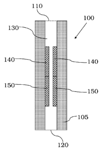
[0016] FIG. 1 is an illustration of a sorbent device including a longitudinal
diffusion path, in
accordance with certain examples;
[0017] FIGS. 2A and 2B are illustrations of sorbent devices including void
space between
the sorbent materials, in accordance with certain examples;
[0018] FIGS. 3A-3D are illustrations of sorbent devices including longitudinal
diffusion
paths with variable spacing, in accordance with certain examples;
[0019] FIGS. 4A and 4B are illustrations showing that sorbent material can be
disposed to
provide a longitudinal diffusion path with a substantially constant cross-
sectional diameter, in
accordance with certain examples;
[0020] FIGS. 5A-5C are illustrations of sorbent devices including three, four
or five
different sorbent materials, in accordance with certain examples;
[0021] FIGS. 6A and 6B are illustrations of pluggable sorbent devices and FIG.
6C is an
illustration showing the coupling of the devices of FIGS. 6A and 6B, in
accordance with
certain examples;
[0022] FIGS. 7A-7D are illustration of sorbent devices formed from coupling
pluggable
sorbent devices, in accordance with certain examples;
6b
CA 02755966 2011 09 19
WO 2010/111222 PCT/US2010/028236
[0023] FIG. 8 is an illustration of a sorbent device including an inner
arrangement of sorbent
materials, in accordance with certain examples;
[0024] FIG. 9 is an illustration of a sorbent device including an inner
arrangement of sorbent
materials and including a material coupled to the sorbent material adjacent to
the sampling
inlet, in accordance with certain examples;
[0025] FIG. 10 is an illustration of a sorbent device including a non-
adsorbing material to
the sorbent material nearest to the sampling inlet, in accordance with certain
examples;
[0026] FIG. 11 is an illustration of a sorbent device including a tapered
arrangement of
sorbent materials, in accordance with certain examples;
[0027] FIG. 12 is an illustration of a sorbent device including a palindromic
arrangement of
sorbent materials, in accordance with certain examples;
[0028] FIG. 13 is an illustration of a sorbent device including a palindromic
arrangement of
sorbent materials and a gas port, in accordance with certain examples; and
[0029] FIG. 14 is a schematic of a thermal desorption analyzer, in accordance
with certain
examples.
[0030] Certain dimensions and components shown in the figures may have been
enlarged,
distorted, exaggerated or otherwise shown in a non-conventional manner to
facilitate a better
understanding of the technology described herein. The lengths, widths, cross-
sectional shapes
and the like shown in the figures are merely illustrative, and other lengths,
widths and cross-
sectional shapes will be readily selected by the person of ordinary skill in
the art, given the
benefit of this disclosure.
DETAILED DESCRIPTION
[0031] Examples of the sorbent devices described herein can be used in many
different
applications including, but not limited to, indoor and outdoor air monitoring,
analysis of the
offgasing of soil, water, biofuels, polymers, packaging materials, flavors and
fragrances,
cosmetics, exhaust gases, and many other applications where volatile species
may be present.
The particular materials selected for inclusion in the sorbent devices may
vary depending on
the particular species to be analyzed. The term sorbent device is used for
convenience
purposes only, and the sorbent devices described herein are effective to
adsorb (or absorb) and
desorb analyte species. In certain embodiments, by selecting combinations of
different sorbent
materials, the sorbent devices are effective to passively sample air species
including samples
having a broad molecular weight range of analytes.
7
CA 02755966 2011 09 19
WO 2010/111222 PCT/US2010/028236
[0032] In certain embodiments, the sorbent devices described herein include
two or more
different types of a packing material, also referred to herein as a sorbent
material that can be
used for adsorption. In some examples described herein, each sorbent material
can be present
in an individual sorbent device that is coupled or plugged to another sorbent
device including a
different sorbent material such that the diffusion paths of each device are
fluidically coupled to
each other.
[0033] In certain examples, the sorbent devices described herein can be used
with
chromatographic analysis to determine the constituents of a particular
environment. For
example, it is often desirable to detect the amount of volatile organic
compounds (VOCs)
present in a certain sample of air. The VOCs may be collected by drawing a
sample of gas
(typically ambient air) through such a tube using a syringe, small vacuum
pump, or other
means. This latter method is commonly referred to as "pumped sampling." In
each case, the
analytes to be measured, e.g., the VOCs, are retained by the sorbent material
as the air passes
through the sorbent device. Once the VOCs are collected, the sorbent device
having the
adsorbed analytes is subsequently heated in a thermal desorption instrument,
and a flow of
inert gas, such as helium, nitrogen or hydrogen, is provided to sweep the VOCs
out of the
sorbent device and into a chromatographic column for separation and analysis.
[0034] In certain examples, the sorbent devices disclosed herein can be
advantageously used
in passive sampling processes where ambient air is permitted to diffuse into
the sorbent device
without the assistance of a pump or other means. Passive sampling permits the
use of fewer
mechanical parts, uses substantially no energy and increases the overall
applications of the
sorbent devices described herein. In particular, the sorbent devices described
herein can be
used in any setting where it is desirable to analyze species in an air source
using diffusive
monitoring. Such air sources may exist, for example, in industrial settings,
home settings or in
other settings that may include one or more species dissolved in the ambient
air (or other air
sources).
[0035] In certain examples, the sorbent devices described herein can be used
in soil vapor
intrusion analyses. Soil vapor intrusion occurs when toxic compounds that are
present in the
air space in soil of a contaminated location enter a building, potentially
creating a health risk.
Many contaminated sites have high diesel levels and toxic polynuclear aromatic
compounds, in
addition to the current EPA air toxics list of components. When sampling sites
using currently
available desorption tubes, diesel entering the tube would not be easily
released thereby
rendering the tube unusable for re-sampling. In addition, because of the
strong adsorptive
nature of the tube, polynuclear aromatic compounds with boiling points above
naphthalene are
8
CA 02755966 2011 09 19
WO 2010/111222 PCT/US2010/028236
not quantitatively desorbed from the tube, making the quantitative
investigation of these
compounds difficult or not possible. Also, when initially sampling a site,
there are many
unknown compounds. The EPA has identified target analytes that are of health
concern which
need to be captured by the tubes; however, these sites contain other compounds
which are not
regulated. Thus, these unknown compounds may interfere with the analysis or
may not be
detected using current tube designs. The sorbent devices described herein can
be placed in or
above the soil for a desired time to permit diffusion of species into the
sorbent device. The
device can then be removed and analyzed using, for example, thermal desorption
analysis.
[0036] In certain examples, an illustration of a sorbent device is shown in
FIG. 1. The
sorbent device 100 includes a sampling inlet 110, a base 120, which is
referred to in some
instances herein as a sampling outlet, and a longitudinal diffusion path 130
between the
sampling inlet 110 and the base 120. The terms inlet and outlet are used for
convenience
purposes only and are generally described in reference to the order of the
sorbent materials in
the sorbent device 100. For example, the sorbent materials in the device are
typically arranged
from a material with a weakest sorbent strength to a material with a strongest
sorbent strength
with the weakest sorbent strength material adjacent to the sampling inlet.
Such ordering
provides several advantages including the ability to adsorb many different
types of species
using a single sorbent device. The terms stronger and weaker are relative
terms, and the
adsorption strength and desorption efficiency are functions of surface area,
pore size(s) and
shape(s), pore volume and surface chemistry of the sorbent materials. No
absolute strength is
required, rather the various materials that are used are stronger or weaker
adsorbers relative to
another material. It will be within the ability of the person of ordinary
skill in the art, given the
benefit of this disclosure, to select a material that is stronger or weaker
than another material.
Higher boiling point compounds are typically retained by the weaker sorbent
materials, and the
lighter analytes break through and are retained by the stronger sorbent
materials. Thus, when
compounds are adsorbed to the sorbent devices, the high boiling point
materials would be
located in sorbent material adjacent to the sampling inlet (or desorption
outlet), and the low
boiling point materials would be adsorbed on sorbent materials closer to the
sampling outlet (or
desorption inlet). Some even lighter components (like gases) break through and
are retained
by the strongest adsorbent immediately adjacent to the sampling outlet. The
particular
ordering of sorbent materials may be selected to increase the probability that
all species adsorb
and then desorb from the sorbent device. For example, it may be desirable to
leave sites in the
stronger sorbent material to be available to adsorb the lighter components. In
addition, if the
higher molecular weight analytes become adsorbed to the stronger or strongest
sorbent
9
CA 02755966 2011 09 19
WO 2010/111222 PCT/US2010/028236
material, they may not desorb. By permitting diffusion in one direction and
desorbing in the
opposite direction, the higher molecular weight materials do not occupy or
enter into the
stronger sorbent materials, which increases the likelihood that they will
fully desorb from the
sorbent device. As described herein, the sampling outlet is typically closed
or sealed, at least
for some part during the sampling procedure, such that fluid is permitted to
diffuse into the
device through the sampling inlet but not the base. For example, the area of
the sorbent device
100 referred to as the base 120 can be closed or sealed such that air does not
diffuse into the
sorbent device 100 through the base 120. During analysis the base 120 can be
opened such
that a fluid carrier can be provided through the base to desorb species from
the sorbent device
100.
[0037] In certain embodiments and in addition to the problems encountered with
heavier
hydrocarbon species, many lighter species can break through, e.g., may adsorb
in only small
quantities or not at all or may desorb too quickly, which can reduce the
likelihood these species
are detected at all or can lead to errors in quantitation. Also, many
government regulations
have decreased the detection limits required for soil vapor intrusion testing.
Extending the
sampling volume to decrease detection limits can cause a problem of break
through for many
lighter components when using available sampling devices. By including a
series of sorbent
materials with staggered strengths in the sorbent devices, the likelihood of
break through can
be reduced.
[0038] Referring again to FIG. 1, the sorbent device 100 is shown as including
two sorbent
materials 140, 150 disposed generally on the inner surfaces of the body 105 of
the sorbent
device 100. The longitudinal diffusion path 130 is fluidically coupled to each
of the sorbent
materials 140, 150 such that species that diffuse into the sorbent device 100
through the
sampling inlet 110 can diffuse down the longitudinal diffusion path 130 where
they are
adsorbed in one or both of the sorbent materials 140, 150. As discussed
herein, the sorbent
material 150 is typically a stronger sorbent material than the sorbent
material 140. After the
species are adsorbed, the sampling inlet 110 can be capped or covered, and the
sorbent device
100 can be stored for future analysis or can be analyzed immediately using
thermal desorption
analyses as described herein.
[0039] In certain examples, the sorbent devices can include an air gap between
the sampling
inlet 110 and the sorbent material 140. While not required, the air gap may be
desirable to
balance out any air flows or, for example, buffer any sudden changes in
concentration in the
external sample and prevent spurious results. Where an air gap is present, the
air gap may
CA 02755966 2011 09 19
WO 2010/111222 PCT/US2010/028236
have a length of about 2 mm to about 30 mm, for example about 5 mm to about 35
mm, e.g.,
mm, 15 mm or 20 mm.
[0040] In some examples, the sampling inlet can include a mesh, cap or other
barrier if
desired. The barrier can be fluid permeable such that, for example, sample
fluid vapors can
diffuse but not flow into the sorbent device. For example, a metal mesh can be
present across
the sampling inlet 110. This mesh can assist, for example, in preventing air
movement within
the air gap as a result of wind or the tube being carried so that only
diffusive transfer of the
molecules to the adsorbents occurs. This mesh may be permanent or may be
present in the
form of a cap that is coupled to the sampling inlet prior to use. Other
configurations are also
possible.
[0041] In some examples, the sorbent devices described herein can be
configured with one
or more void spaces between the different sorbent materials. Referring to
FIGS. 2A and 2B, a
sorbent device 200 can include first and second sorbent materials 210, 220
having void spaces
230, 240 between the sorbent materials 210, 220. As shown in FIG. 2A, the void
spaces 230,
240 can be substantially the same to facilitate easier deposition of the
sorbent materials 210,
220 in the sorbent device. For example, a mask or spacer (not shown) can be
inserted between
sorbent materials 210, 220 to provide a void space between the sorbent
materials 230, 240. In
other examples, the void space may be unequal at different portions of the
sorbent device.
Referring to FIG. 2B, a sorbent device 250 can include first and second
sorbent materials 260,
270 having void spaces 280, 290 between the sorbent materials 260, 270. As
shown in FIG.
2B, the spacing of the void spaces 280, 290 are not the same. To create
unequal spacing, some
portion of one or more of the sorbent materials can be removed or otherwise
not disposed in
the sorbent device. For example, it may be desirable to have an unequal
distribution of the
sorbent materials in the device to increase or decrease adsorption at a
particular area of the
device.
[0042] Notwithstanding that the sorbent device can include sorbent materials
disposed
within it in various manners, the longitudinal diffusion path of the sorbent
device typically is
open, at least to some degree, such that fluids such as gasses can flow into
the different areas of
the sorbent device through diffusional processes. Referring to FIG. 3A, a side
view of a
longitudinal diffusion path 306 is shown. The flow path 306 has substantially
the same cross-
sectional shape and diameter along the entire length of the flow path 306 from
the sampling
inlet 302 to the sampling outlet 304. The longitudinal diffusion path can also
have a variable
shape or cross-sectional diameter. Referring to FIG. 3B, a longitudinal
diffusion path 316 has
a greater cross-sectional diameter at a sampling inlet 312 than at base 314.
Referring to FIG.
11
CA 02755966 2011 09 19
WO 2010/111222 PCT/US2010/028236
3C, a longitudinal diffusion path 326 has a smaller cross-sectional diameter
at a sampling inlet
322 than at a base 324. Referring to FIG. 3D, a longitudinal diffusion path
336 has
substantially the same cross-sectional diameter at a sampling inlet 332 and a
sampling outlet
334, but the cross-sectional diameter along the length of the flow path
varies. The
embodiments shown in FIGS. 3A-3D are merely illustrative and other variable
size
longitudinal diffusion paths may be used in the sorbent devices described
herein. As discussed
further below, the particular shape and dimensions of the diffusion path can
vary and may be
selected, for example, based on the anticipated analytes that are present in a
sample.
[0043] In certain embodiments, the diameter of the interior volume that forms
the
longitudinal diffusion path may be variable prior to disposition of any
sorbent material in the
interior but then have a substantially uniform channel after disposition of
the sorbent material.
For example and referring to FIGS. 4A and 4B, a sorbent device 400 is shown in
FIG. 4A as
including a variable size longitudinal diffusion path 406, with the diameter
of the diffusion
path 406 near a sampling inlet 402 greater than the diameter near a sampling
outlet 404.
Referring to FIG. 4B, after disposition of sorbent materials 410 and 420 in
the sorbent device
400, a longitudinal diffusion path 430 is formed that has substantially the
same cross-sectional
diameter. In some examples, to form the longitudinal diffusion path 430, the
sorbent material
420 can first be packed into the body of the sorbent device 400 to a desired
depth. The sorbent
material 410 can then be packed on top of the sorbent material 420 to a
desired depth. A hole
or channel can be drilled or machined into the packed sorbent materials 410,
420 to provide the
longitudinal diffusion path 430. Other methods may also be used and are
described in more
detail herein.
[0044] In certain examples, the sorbent devices described herein can be
produced by packing
one or more sorbent materials in a suitable body. For example, the strongest
sorbent material
can be placed in a hollow tube and packed against a seal, mesh or other
material adjacent to or
in the sampling outlet. A second sorbent material can be placed directly on
the first sorbent
material, or a mesh, fluid permeable barrier or other material can be used to
physically separate
the two sorbent materials. A longitudinal diffusion path can then be drilled
or machined into
the disposed sorbent materials by producing a longitudinal channel through the
disposed
sorbent materials. If desired, the sampling inlet may include a mesh material
or other desired
material to assist in retention of the sorbent material in the sorbent device.
[0045] In other examples, a carrier, e.g., a sleeve, can be inserted into the
longitudinal
opening of the sorbent device, and sorbent material can be packed around the
sleeve. If
desired, one or more barriers, e.g., fluid permeable barriers, or other
materials may be inserted
12
CA 02755966 2011 09 19
WO 2010/111222 PCT/US2010/028236
onto the carrier to separate the sorbent materials. The carrier can then be
removed to provide a
longitudinal channel or opening, around which the sorbent material is packed,
that is operative
as a longitudinal diffusion path.
[0046] In some embodiments, the carrier may remain in place once the sorbent
material is
packed. If so, then the carrier may be porous or may be a mesh material such
that fluid can
flow between the longitudinal diffusion path and the sorbent material. In
certain examples, the
sorbent material may be packed between the sleeve and the body of the sorbent
device,
whereas in other examples, the sorbent material may be impregnated in or
embedded, to at
least some degree, in the carrier. Where a carrier is present, the carrier
desirably includes one
or more materials that can withstand the thermal desorption temperatures
commonly used in
thermal desorption analysis. In certain examples, the sorbent materials can be
deposited on the
carrier and then the assembly is inserted into the body of the sorbent device.
[0047] In certain examples, a fluid permeable barrier can be used to separate
the various
sorbent materials in the sorbent device. The fluid permeable barrier can also
be used to retain
the sorbent material in the sorbent device. For example, a fluid permeable
barrier can be
inserted into a hollow tube such that the strongest sorbent material will be
disposed on the fluid
permeable barrier near the sampling outlet. Alternatively, a non-permeable
barrier can be
placed at the sampling outlet such that diffusion of sample occurs in only one
direction, e.g.,
from the sampling inlet to the sampling outlet. An additional fluid permeable
barrier can be
placed on the deposited first sorbent material to separate it from the second
sorbent material.
This process can be repeated until a desired amount and type of sorbent
materials have been
deposited in the sorbent device. At the sampling inlet of the sorbent device,
a mesh, clip or
other retention device can be placed to hold the sorbent materials in the
sorbent device.
[0048] In other examples, the sorbent materials can be chemically bonded to
the inner
surface of the body of the sorbent device. Such bonding may occur using
techniques
commonly employed in the manufacture of porous open layer tubular columns or
solid phase
micro extraction columns. Other techniques such as gas deposition, vapor
deposition or the
like can also be used to deposit the materials in the sorbent devices.
[0049] In certain embodiments, more than two materials can be used in a
sorbent device.
For example, it may be desirable to include three, four, five, six, seven or
more types of
sorbent materials within the sorbent devices to facilitate analysis of a
plurality of species in a
sample. The number of sorbent materials used in the sorbent devices can vary
depending on
the number of analytes and the types of analytes suspected to be present.
Where the number
and type of analytes are unknown, a sorbent device including a plurality of
different types of
13
CA 02755966 2011 09 19
WO 2010/111222 PCT/US2010/028236
sorbent materials can be used to ensure that substantially all of the analytes
can be analyzed.
In one embodiment where four or more sorbent materials are used, the sorbent
materials can be
arranged from weakest to strongest with the weakest sorbent material being
closest to the
sampling inlet and the strongest sorbent material being closest to the
sampling outlet.
[0050] In certain examples, it may be desirable to include a particular
sorbent material in a
larger amount that the other sorbent materials. For example, where a sample is
suspected of
having a large concentration of a particular analyte, the sorbent material
effective to adsorb and
desorb that analyte may be present in a larger amount/volume to provide for
increased loading
of that analyte. The amount of the analyte can be increased or the surface
area accessible to
the analyte can be increased to assist in increased adsorption of that analyte
to the sorbent
device. Alternatively, it may be desirable to include more of the stronger
sorbent materials to
increase the overall likelihood that highly volatile compounds will adsorb to
the sorbent
device.
[0051] In certain embodiments and as described herein, the exact number and
type of
sorbent materials present in the sorbent device can vary and may include, for
example, two,
three, four, five, six or more. Illustrative examples of a sorbent device 510
that includes four
sorbent materials, a sorbent device 520 that includes five sorbent materials
and a sorbent
device 530 that includes six sorbent materials are shown in FIGS. 5A-5C,
respectively. These
illustrative devices can include a carrier, or if desired, the carrier can be
absent. While the
devices shown in FIGS. 5A-5C are shown as lacking void space between the
different sorbent
materials, void spaces, which may have the same or different spacing, may be
present if
desired. In addition, it may be desirable to increase the overall length of
the sorbent device to
accommodate additional sorbent materials.
[0052] In certain examples, the sorbent materials can each be present at
substantially the
same weight ratio, e.g., 1:1. In other examples, the different sorbent
materials can
independently be present in weight ratios ranging from 3:1, 2.5:1, 2:1, 1.5:1,
1.1:1, 0.9:1, 0.8:1,
0.7:1, 0.6:1, 0.5:1, 0.4:1, 0.3:1, 0.2:1, 0.1:1 or any ratio in between these
illustrative ratios. It
may be desirable to determine the relative weight ratios using the first
sorbent material (the one
closest to the sampling inlet) as the normalization factor, and the amount of
each of the other
sorbent materials that is present can be divided by the amount of the first
sorbent material that
is present to determine the relative weight ratios present in the sorbent
device. Additional
suitable amounts of the sorbent materials will be readily selected by the
person of ordinary
skill in the art, given the benefit of this disclosure.
14
CA 02755966 2011 09 19
WO 2010/111222 PCT/US2010/028236
[0053] In certain embodiments, the sorbent materials may be individually
packed into
sorbent devices that can be fluidically coupled to each other to provide a
pluggable sorbent
device. For example and referring to FIGS. 6A-6C, a first sorbent device 600
can include a
sampling inlet 602, a base 604 and a longitudinal diffusion path 606 between
the inlet 602 and
the base 604. A first sorbent material 608 is shown as being present in the
first sorbent device
600. A second sorbent device 610 can include a sampling inlet 612, a base 614
and a
longitudinal diffusion path 616 between the inlet 612 and the base 614. A
second sorbent
material 618 is shown as being present in the second sorbent device 610. The
two sorbent
devices can be plugged into each other or otherwise coupled by coupling the
base or sampling
outlet 604 of the first sorbent device 600 to the sampling inlet 612 of the
second sorbent device
610. In this manner, the longitudinal diffusion paths 606 and 616 become
fluidically coupled
to each other as shown in FIG. 6C. Depending on the strength of the sorbent
materials relative
to each other, it may be desirable to instead couple the devices by coupling
the sampling outlet
614 of the second sorbent device 610 to the sampling inlet 602 of the first
sorbent device 600.
Such pluggable sorbent devices provide increased flexibility as a user can
decide the particular
type, order and number of sorbent materials that can be present. For example,
a user may piece
together a selected number of pluggable sorbent devices on-site to analyze an
air sample. Such
flexibility is desired particularly where an environment may include a large
number of analytes
in a sample. In some examples, two, three, four, five, six or more pluggable
devices, each
including a different sorbent material, can be coupled to each other to
provide a sorbent device.
Illustrations of sorbent devices including three, four, five and six
individual pluggable sorbent
devices that are shown as devices 710, 720, 730 and 740, respectively, in
FIGS. 7A-7D,
respectively. For example, device 710 includes sorbent materials 712, 714 and
716, device 720
includes sorbent materials 722, 724, 726 and 728, device 730 includes sorbent
materials 731,
733, 735, 737 and 739 and device 740 includes sorbent materials 741, 742, 743,
744, 745 and
746. The pluggable sorbent devices may include one or more fittings to provide
a substantially
tight fluid seal between the sorbent devices when coupled. For example,
threads, gaskets,
washers or the like can be included to effectuate coupling and the provision
of a fluid tight seal
between different pluggable sorbent devices.
[0054] In certain examples, the sorbent materials need not be disposed against
the inner
walls of the sorbent devices. In some examples, the sorbent materials can be
disposed in an
interior portion of the sorbent device to permit diffusion of sample around
the sorbent
materials. For example and referring to FIG. 8, a sorbent device 800 includes
a plurality of
sorbent materials 830, 832, 834, 836, 838 and 840 deposited substantially
concentrically within
CA 02755966 2011 09 19
WO 2010/111222 PCT/US2010/028236
a body 805 of the sorbent device 800. The sorbent device 800 also includes a
sampling inlet
810 and a base or sampling outlet 820. While not shown, the sorbent device can
include, if
desired, radial arms or radial support structures to retain the sorbent media
within the sorbent
device. The packing configuration shown in FIG. 8 permits the use of a
longitudinal diffusion
path 825 between the walls of the body 805 of the sorbent device 800 and the
packed sorbent
materials 830-840. As shown in FIG. 8, the top of the sorbent device 810 is
open in that no
barrier or mesh is present. If desired, the top sorbent material can include a
mesh or other
material to prevent fluid flow into the top of the sorbent material. For
example and referring to
FIG. 9, a sorbent device 900 includes a plurality of sorbent materials 930-940
with the weakest
sorbent material 930 nearest a sampling inlet 910 and the strongest sorbent
material 940 near
the base or sampling outlet 920. A longitudinal diffusion path 925 exists
around the sorbent
materials 930-940. A mesh or barrier 950 can be deposited on the sorbent
material 930 if
desired to assist, for example, in proper diffusion of the sample species
around the sorbent
materials 930-940.
[0055] In certain embodiments, it may be desirable to provide a non-adsorbing
material on
the top of the sorbent materials. For example and referring to FIG. 10, a
sorbent device 1000 is
shown as including a plurality of sorbent materials 1030, 1032, 1034, 1036,
1038 and 1040
deposited substantially concentrically within a body 1005 of the sorbent
device 1000. The
sorbent device 1000 also includes a sampling inlet 1010 and base or a sampling
outlet 1020.
The configuration shown in FIG. 10 permits the use of a longitudinal diffusion
path 1025
between the walls of the body 1005 of the sorbent device 1000 and the packed
sorbent
materials 1030-1040. A non-adsorbing material 1050 can be present and adjacent
to the
sorbent material 1030. The non-adsorbing material 1050 can provide, for
example, a uniform
air gap around the sorbent materials 1030-1040. If desired, a mesh or other
barrier can be
present between the non-adsorbing material 1050 and the sorbent material 1030.
In some
examples, the non-adsorbing material can take the form of a cap, spacer or
other material.
[0056] In certain embodiments, the overall length of the sorbent device can
vary from about
50 mm to about 120 mm, e.g., about 60 mm to about 100 mm or about 80-90 mm,
for example
about 88 mm. In certain examples, the sorbent material can occupy about 50-80%
of the
length of the sorbent device. For example, the sorbent material may occupy
about 25-95 mm
of the length of the sorbent device, e.g., about 45-70mm or about 60 mm of the
sorbent device
length may include one or more sorbent materials. In some examples, the
diameter of the
sorbent device can vary from about 1 mm to about 10 mm, for example about 3 mm
to about 8
16
CA 02755966 2011 09 19
WO 2010/111222 PCT/US2010/028236
mm, e.g., about 4-6 mm or about 5 mm. In some examples, the longitudinal
diffusion path
may have about the same length as the sorbent device or may have a shorter
length.
[0057] In some examples where the sorbent materials are disposed within the
interior of the
sorbent device, the shape and configuration of the sorbent materials can be
different from other
sorbent materials in the device. For example and referring to FIG. 11, a
sorbent device 1100 is
shown as including a plurality of sorbent materials 1130-1140. The sorbent
materials 1030-
1040 are tapered in that the diameter of the sorbent material 1140 is greater
than the diameter
of the sorbent material 1130. The tapering could be reversed or the tapering
could have a
symmetric axis such that the inner sorbent materials have less diameter than
the top and bottom
sorbent materials. Other configurations are also possible including, for
example, where the
sorbent tapering is combined with tapering of the interior channel of the body
of the sorbent
device. In particular, depending on the desired diffusional characteristics of
the sorbent device,
the particular configuration of the sorbent materials and longitudinal
diffusion path can be
varied.
[0058] In embodiments that employ an internal arrangement of sorbent
materials, e.g., those
illustrative embodiments shown in FIGS. 8-11, the sorbent materials can be
disposed in the
devices in numerous manners. In one example, a hollow sleeve can be inserted
into the sorbent
device and the materials can be added to the interior of the hollow sleeve.
Once packed, the
hollow sleeve can be removed to provide the longitudinal diffusion path around
the packed
sorbent materials. In other examples, the sorbent device can be packed and
material adjacent
to the wall can be removed to provide a longitudinal diffusion path. In yet
other examples, the
sorbent materials can be disposed in a first tube and then removed and
inserted into a different
tube having a larger diameter such that a longitudinal diffusion path exists
between the sorbent
material and the inner wall of the sorbent device. These methods are
illustrative of suitable
methods for disposing sorbent materials, and additional suitable methods will
be readily
selected by the person of ordinary skill in the art, given the benefit of this
disclosure.
[0059] In certain embodiments, the sorbent materials may be arranged in a
palindromic
configuration with a sorbent device such that the sorbent materials are
substantially symmetric
about a central axis. For example and referring to FIG. 12, a sorbent device
1200 includes two
sampling inlets 1210, 1220, and a longitudinal diffusion path 1230 between the
inlets 1210,
1220. A first sorbent material 1240 is positioned adjacent to each of the
sampling inlets 1210,
1220. A second sorbent material 1250 is positioned internally within the
longitudinal diffusion
path 1230 in the body 1205 of the sorbent device 1200. The first sorbent
material 1240 has a
weaker sorbent strength than the second sorbent material 1250. A minor plane
is present in
17
CA 02755966 2011 09 19
WO 2010/111222 PCT/US2010/028236
the central part of the body with respect to the ordering of the sorbent
materials 1240, 1250. In
this configuration, sample may be permitted to diffuse into each of the
sampling inlets 1210,
1220. After sampling, the sorbent device can be analyzed by introducing a
carrier gas into the
sorbent device 1200. If desired, the sorbent device can be broken or cut into
two or more
pieces such that carrier gas can be introduced in an opposite direction from
the direction of
sample diffusion into the sorbent device 1200.
[0060] In other examples, the sorbent device may include a gas port or the
like at a central
location on the sorbent device body. The gas port can be used to introduce a
carrier gas into
the sorbent device after sampling. One illustration is shown in FIG. 13. The
sorbent device
1300 includes two sampling inlets 1310, 1320 and a longitudinal diffusion path
1330 between
the inlets 1310, 1320. A first sorbent material 1340 is positioned adjacent to
each of the
sampling inlets 1310, 1320. A second sorbent material 1350 is positioned
internally within the
longitudinal diffusion path 1330 in the body 1305 of the sorbent device 1300.
The first sorbent
material 1340 has a weaker sorbent strength than the second sorbent material
1350. A gas port
1360 in the body 1305 can be present. During sampling the gas port 1360 is
typically closed or
sealed such that fluid does not diffuse into the device 1300 through the gas
port 1360. When
the sorbent device 1300 is being analyzed, a carrier gas can be introduced
into the sorbent
device 1300 through the gas port 1360 such that species can desorb from the
sorbent materials
1340, 1350 and exit the sorbent device through the inlets 1310, 1320. It may
be desirable to
fluidically couple one or more chromatography columns to each of the inlets
1310, 1320 to
separate species exiting the sorbent device 1300. A single chromatography
column can be
used or different chromatography columns can be coupled to each of the inlets
1310, 1320.
[0061] While the palindromic arrangement shown in FIGS. 12 and 13 includes two
different
sorbent materials, three, four, five, six or more sorbent materials may
instead be arranged in a
similar manner. In addition, the sorbent materials can be tapered or otherwise
present in
different amounts or configurations in the palindromic sorbent devices
described herein. In
some examples, the palindromic configuration may include sorbent materials
disposed on the
inner surfaces of the sorbent device, whereas in other palindromic
configurations, the sorbent
materials may be concentrically disposed similar to those configuration shown,
for example, in
FIGS. 8-11. In addition, pluggable sorbent devices can be coupled in a
suitable manner to
provide a palindromic configuration of sorbent materials in the coupled
device.
[0062] In certain embodiments, one or more of the sorbent material types used
in the sorbent
devices described herein may be based on, or include, one or more of charcoal,
carbon blacks
(e.g., e.g. CarboTrap TM and CarboPackTM products), carbon-molecular sieves
(e.g.,
18
CA 02755966 2011 09 19
WO 2010/111222 PCT/US2010/028236
CarboSieveTm and CarboxenTm products), porous polymers (e.g., TenaxTm,
PorapakTm,
HayesSep TM products), silicones (e.g., polydimethylsiloxane (PDMS)),
molecular sieves, silica
gels or may include other materials.
[0063] In some examples, the sorbent material can be a graphitized carbon
black, a carbon
molecular sieve, or combinations thereof. In some examples, the sorbent
material may be
include, or be based on a mixture of, graphitized carbon blacks of different
strengths, graphite,
carbon molecular sieves, polymer resins, an oxide, fused silica beads, glass,
quartz, charcoal,
porous polymers, amisorbs or other materials. In certain embodiments, the
different sorbent
material in the sorbent devices may have a different chemical composition,
e.g., each may
include or be a different carbon black. In some examples, the sorbent material
may be a
derivatized form, e.g., a derivatized carbon black.
[0064] In some examples, the sorbent material can be a graphitized carbon
black such as,
for example, CarbotrapTm B sorbent or CarbopackTm B sorbent, CarbotrapTm Z
sorbent or
CarbopackTm Z sorbent, CarbotrapTm C sorbent or CarbopackTm C sorbent,
CarbotrapTm X
sorbent or CarbopackTM X sorbent, CarbotrapTm Y sorbent or CarbopackTm Y
sorbent,
CarbotrapTm F sorbent or CarbopackTm F sorbent, any one or more of which may
be used in its
commercial form (available commercially from Supelco or Sigma-Aldrich) or may
be
graphitized according to known protocols. In other examples, the sorbent
material can be
carbon molecular sieves such as CarboxenTM 1000 sorbent, CarboxenTM 1003
sorbent, or
CarboxenTm-1016 sorbent, any one or more of which may be used in its
commercial form
(available commercially from Supelco or Sigma-Aldrich) or may be optimized
according to
known protocols. In certain embodiments where four different sorbent materials
are present,
each of the sorbent materials may be one of the sorbent materials listed in
this paragraph with
each of the sorbent materials being a different sorbent material than the
other sorbent materials
used in the sorbent device. In such instances, four different sorbent
materials would be present
in the sorbent device.
[0065] In certain examples, the mesh size or range of the sorbent can vary
depending on the
particular material selected. In some examples, the mesh size can range from
20 to about 100,
more particular from about 20-80, 30-70 or 40-60. In other examples, the mesh
size range may
be from about 20-40, 40-60, 60-80 or 80-100 depending on the material used in
the sorbent
devices. Other suitable mesh sizes will be readily selected by the person of
ordinary skill in
the art, given the benefit of this disclosure.
[0066] In certain embodiments, the body of the sorbent device may be made
from, or
include, many different types of materials. In some examples, quartz,
stainless steel, coated
19
CA 02755966 2011 09 19
WO 2010/111222 PCT/US2010/028236
stainless steel or other metal or non-metal based materials that can tolerate
the temperature
cycles used to desorb the analytes can desirably be used.
[0067] In certain embodiments, the sorbent devices described herein can be
used with
automated thermal desorption (ATD) gas chromatography system. In one
embodiment, ATD
works by heating the sorbent device for a required amount of time to release
volatiles from the
sorbent material. During this heating, a carrier gas such as helium, nitrogen
or hydrogen flows
through the tube at a desired flow rate to transfer the contents of the
sorbent tube onto a cooled
secondary trap via a carrier gas, which is typically helium or hydrogen. This
trap is then
rapidly heated to desorb the collected components in a narrow band into the GC
column for
separation. A mass spectrometer is the most common detector used to provide
the analysis.
The information is sent to a computer containing an application which sends
information to the
instrument for control and collects information from the detector for
analysis. This application
has the ability to process this information which can provide quantitative and
qualitative
results.
[0068] By including many different types of sorbent materials in the sorbent
devices, it may
be possible to use a single desorption cycle to desorb substantially all
adsorbed species. Such
desorption typically permits reuse of the sorbent device without further
temperature treatment,
e.g., baking for extended periods, to remove high molecular weight species.
[0069] In certain embodiments, the sorbent devices described herein may be
particularly
advantageous for use where it is desirable to continuously monitor the air
quality in an air
space occupied by animals such as humans. For example, air may be periodically
sampled in
an airplane cabin, cockpit, spacecraft cabin, space station or the like for
the presence of volatile
species that may lead to adverse health effects.
[0070] In certain examples, the sorbent devices described herein can be used
with one or
more instruments that are controlled or otherwise operated by, at least in
part, a computer
system. An illustrative system is shown in FIG. 14. The system 1400 includes a
carrier gas
supply 1410 fluidically coupled to a sorbent device 1420, which may be any of
those described
herein. Suitable valving or other devices may be present in the system to
permit or restrict
fluid flow between the carrier gas supply 1210 and the sorbent device 1420,
depending on the
desired flow of the carrier gas. In some examples, an injector may also be
fluidically coupled
to the sorbent device 1420 and/or carrier gas supply 1410, if desired. The
sorbent device 1420
is fluidically coupled to a column 1430, which is effective to separate
species based on their
partitioning between the mobile phase and the column's stationary phase.
Species that elute
from the column 1430 are provided to a detector 1440, which can analyze those
species based
CA 02755966 2016-12-20
54592-2
on chemical or physical properties. The detector can be any of those detectors
commonly used
in gas chromatographic systems including, but not limited to, a mass
spectrometer, a flame
ionization detector, a thermal conductivity detector, a thermionic detector,
an electron-capture
detector, a discharge ionization detector, a Hall electrolytic conductivity
detector, an atomic
emission detector, a flame photometric detector, a pulsed discharge ionization
detector, a
photoionization detector and other suitable types of detectors. In certain
examples, the system
800 can include a computer system with a user interface such that a user may
enter starting and
final temperatures, temperature ramp parameters, sorbent device materials, and
the like for use
by the computer system in quantifying the analytes adsorbed to the sorbent
devices. For
example, in instances where a user already knows the particular set of
analytes that are present,
the user can select a previously entered chromatographic profile for use in
the analysis. Other
features for inclusion in a user interface will be readily selected by the
person of ordinary skill
in the art, given the benefit of this disclosure. In
some examples, the sorbent devices
described herein can be used with a swafer device such as those described in
commonly
assigned U.S. Patent Application No. 12/472,948 filed on May 27, 2009. In
certain configurations
where a swafer device is used, the carrier gas supply 1210 and the sorbent
device 1220 can be
fluidically coupled to different ports of the swafer device.
[0071] In some examples, the sorbent device can be packaged in a kit
optionally containing
other components. For example, a kit may include one or more of the sorbent
devices
described herein optionally with other sorbent devices. Where the sorbent
device takes the
form of a pluggable sorbent device, a plurality of pluggable sorbent devices
can be present
each having a different sorbent medium such that an end-user can plug desired
sorbent devices
together to fluidically couple the longitudinal diffusion paths. The kit can
also include other
desirable components useful in sampling or analysis including, but not limited
to, one or more
standards, caps, covers, fittings, couplings or the like. In some examples,
the kit can include a
thermal desorption analyzer for use with the sorbent device.
[0072] In certain examples, the sorbent devices described herein are useful
for passive
sampling of species by exposing a sorbent device to an environment comprising
volatile
species to permit volatile species in the environment to passively adsorb to
the sorbent device.
The adsorbed species can be subsequently desorbed to analyze the species
present in the air
sample. The particular sorbent materials used can vary and may be, for
example, four different
sorbent materials comprising a graphitized carbon black or may be a
graphitized carbon black
or a carbon molecular sieve with none of the materials being the same
material.
21
CA 02755966 2011 09 19
WO 2010/111222 PCT/US2010/028236
[0073] In certain embodiments, a method of facilitating passive sampling of an
air space
comprising providing a sorbent device comprising a body comprising a sampling
inlet, a
sampling outlet and a longitudinal diffusion path between the sampling inlet
and the sampling
outlet, the sorbent device further comprising a serial arrangement of at least
two different
sorbent materials each fluidically coupled to the longitudinal diffusion path,
in which the
sorbent materials are arranged from a material with a weakest sorbent strength
to a material
with a strongest sorbent strength with the weakest sorbent strength material
adjacent to the
sampling inlet, in which the sorbent device is effective to adsorb volatile
species in the air
space to sample passively the air space can be used. The sorbent device can be
any one or
more of the sorbent devices described herein.
[0074] In other embodiments, a method of facilitating passive sampling of an
air space
comprising providing at least two pluggable sorbent devices can be performed.
In some
examples, a plurality of pluggable sorbent devices can be provided, e.g.,
three, four, five, six or
more, to increase the number of configurations that are possible for the
sorbent device.
[0075] When introducing elements of the aspects, embodiments and examples
disclosed
herein, the articles "a," "an," "the" and "said" are intended to mean that
there are one or more
of the elements. The terms "comprising," "including" and "having" are intended
to be open-
ended and mean that there may be additional elements other than the listed
elements. It will be
recognized by the person of ordinary skill in the art, given the benefit of
this disclosure, that
various components of the examples can be interchanged or substituted with
various
components in other examples.
[0076] Although certain aspects, examples and embodiments have been described
above, it
will be recognized by the person of ordinary skill in the art, given the
benefit of this disclosure,
that additions, substitutions, modifications, and alterations of the disclosed
illustrative aspects,
examples and embodiments are possible.
22