Note: Descriptions are shown in the official language in which they were submitted.
WO 2010/108068 PCT/US2010/027916
CLAMPED GAS BLOCK FOR BARREL
Cross-Reference to Related Applications
[00011 This application claims the benefit of U.S. Provisional Patent
Application No.
61/162,099, filed March 20, 2009.
Incorporation By Reference
[0002] U.S. Provisional Patent Application No. 61/162,099, which was filed on
March 20, 2009, is hereby incorporated by reference for all purposes as if
presented
herein in its entirety.
Technical Field
[0003] Embodiments of the disclosure are directed generally to gas operated
firearms
and, more particularly, to an apparatus for clamping a gas block to the barrel
of a gas-
operated firearm.
Background Information
[0004] Semi-automatic firearms, such as rifles and shotguns, are designed to
fire a
round of ammunition, such as a cartridge or shot shell, in response to each
squeeze of
the trigger of the firearm, and thereafter automatically load the next shell
or cartridge
from the firearm magazine into the chamber of the firearm. During firing, the
primer
of the round of ammunition ignites the propellant inside the round, producing
an
expanding column of high pressure gases within the chamber and barrel of the
firearm. The force of this expanding gas propels the bullet/shot of the
cartridge or
shell down the barrel.
[0005] In semi-automatic rifles and shotguns, a portion of the expanding gases
typically are directed through a duct or port that interconnects the barrel of
the firearm
to a piston assembly that generally houses an axially moveable piston. This
piston
1
WO 2010/108068 PCTIUS2010/027916
assembly further typically includes a gas block that connects the piston
assembly to
the barrel, and through which the explosive gases pass. In some systems, the
gas
blocks are one piece elements located on their firearms and aligned with the
port in
the barrel through which the gases from the fired cartridge flow into the gas
block and
back to the action for expelling the spent cartridge and for chambering a
fresh
cartridge. The portion of the explosive gases that are diverted from the
barrel of the
firearm act upon the piston so as to force the piston in a rearward direction
to cause
the rearward motion of the bolt of the firearm. This rearward motion of the
bolt opens
the chamber, ejects the empty shell or cartridge casing, and thereafter loads
another
shell or cartridge into the chamber, after which the bolt returns to a locked
position for
firing as the gases dissipate or are bled off.
Summary of the Disclosure
[00061 Briefly described, in one embodiment of the invention, a gas block
clamping
apparatus is provided for use with a gas-operated firearm. The gas block can
comprise a plurality of sections, including an upper section and a lower
cylindrical
section to which the upper section is attached. The upper section further can
have a
profile that is shaped or configured to facilitate its fitting to and mounting
along the
barrel. A plurality of clamp sections are symmetrically disposed on opposite
sides of
the barrel. Each clamp section can have an upper surface for attaching the gas
block
to the barrel, an alignment surface that tends to facilitate alignment of the
clamp
section to the barrel when the clamp sections are tightened against the
barrel, and a
lower surface that aligns with the curved upper section of the gas block. A
plurality
of fasteners generally are disposed through a plurality of openings in the
lower
surface of the clamp sections and the upper surface of the gas block for
securing each
clamp section to both the barrel and gas block.
[00071 These and various other advantages, features, and aspects of the
exemplary
embodiments will become apparent and more readily appreciated from the
following
detailed description of the embodiments taken in conjunction with the
accompanying
drawings, as follows.
2
WO 2010/108068 PCT/US2010/027916
Brief Description of the Drawings
[0008] Fig. 1 illustrates a gas-operated firearm showing the positioning of
the
clamped gas block in an exemplary embodiment.
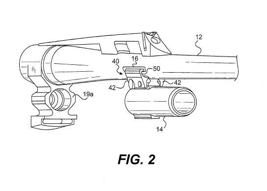
[0009] Fig. 2 is a perspective view of clamped gas block attached to the
firearm barrel
in an exemplary embodiment.
[0010] Fig. 3A is an isometric view of a clamp section of the clamped gas
block of
Fig. 2.
[0011] Fig. 3B is an end view of the clamp section of Fig. 3A illustrating
example
force vectors applied to the clamp section.
[0012] Fig. 4A is an end view of the clamp sections mounted to the firearm
barrel and
clamped gas block in an exemplary embodiment.
[0013] Fig. 4B is a cross-sectional view of the clamped gas block and firearm
barrel
in an exemplary embodiment.
[0014] Fig. 5 is an enlarged perspective view of the clamp section attached to
the
firearm barrel and clamped gas block in an exemplary embodiment.
Detailed Description of the Exemplary Embodiments
[0015] Referring now to the drawings in which like numerals indicate like
parts
throughout the several views, the figures illustrate one example embodiment of
the
clamped gas block apparatus or system according to the principles of the
present
disclosure for use in a firearm such as a rifle. However, it will be
understood that the
clamped gas block apparatus can be used in various types of firearms including
shotguns and other long guns, hand guns, and other gas-operated firearms. The
following description is provided as an enabling teaching of exemplary
embodiments;
and those skilled in the relevant art will recognize that many changes can be
made to
the embodiments described, while still obtaining the beneficial results. It
will also be
apparent that some of the desired benefits of the embodiments described can be
3
WO 2010/108068 PCTIUS2010/027916
obtained by selecting some of the features of the embodiments without
utilizing other
features. Accordingly, those who work in the art will recognize that many
modifications and adaptations to the embodiments described are possible and
may
even be desirable in certain circumstances, and are a part of the invention.
Thus, the
following description is provided as illustrative of the principles of the
embodiments
and not in limitation thereof, since the scope of the invention is defined by
the claims.
[0016] Fig. I illustrates a gas-operated firearm 10 showing the positioning of
the
clamped gas block apparatus or system in one exemplary embodiment. Gas-
operated
firearm 10 generally includes barrel 12, stock 20, receiver 22, fire control
24, and the
clamped gas block apparatus or system 40, including a gas block 14. The stock
20,
also known as the buttstock or shoulder stock, may be formed in any
conventional
manner to include cushioning, special curvatures, grips, etc. The receiver 22
houses
and includes the fining mechanism or fire control 24, including a trigger 23
for
actuating the firearm a breech bolt or bolt assembly 25, and a firing pin. The
bolt
assembly is translatable axially in both forward and rearward directions along
the
receiver during the firing cycle and generally is located behind a chamber
portion 27
located at the proximal end of the barrel 12 adjacent the receiver 22. The
chamber
receives a round of ammunition R, such as a shell or cartridge for firing.
[0017] In the gas-operated semi-automatic firearm 10 illustrated in Fig. 1, a
gas-
operated piston assembly 26 is provided for reloading the chamber after firing
by way
of mechanical interconnection and interaction between the gas redirecting
piston
assembly and the bolt. During a firing operation, a portion of the expanding
gas in the
barrel is redirected into the gas block assembly 14 to drive the gas piston
rearward.
The action of the gas piston, which in turn is translated to the bolt,
functions to
automatically clear or discharge a spent cartridge/shell casing from the
chamber, load
a new round R into the chamber, and recock the firing pin and bolt for a next
firing
cycle.
[0018] According to one embodiment of the clamped gas block apparatus or
system
40, as shown in Figs. 2, 4A, 4B, and 5, generally symmetric clamp sections 42
of the
4
WO 2010/108068 PCTIUS2010/027916
clamped gas block apparatus 40 attach the gas block 14 to the barrel 12 by
engaging
one or more cut out sections (i.e., notches, recesses, or other depressions or
other
engaging areas) 16 formed along the outer surface of the barrel 12. Each of
the
notches 16 generally is an elongate slot with a lower lip 16a adapted to
engage or
cooperate with one of the clamp sections 42. The notches extend at least
partially
along the length of the barrel 12, generally parallel with the central axis of
the barrel,
and can be situated below the horizontal centerline of the barrel. In a
particular
exemplary embodiment, the notches 16 can be machined into the outer surface of
the
barrel 12. Additionally, various shapes and orientations of the notches 16 are
considered to be within the scope of the present invention. For example, all
or part of
the notches, and/or the entirety or a portion of the notches themselves, can
be formed
or oriented generally transverse to the central axis of the barrel 12.
[00191 Fig. 3A shows an isometric view of a clamp section 42 according to one
embodiment of the present disclosure. As illustrated, the clamp section 42 can
include a generally C-shaped member 50, a top portion 52, a clamp protrusion
54, and
a lower flange 56, which can include through-bores 58a, 58b. In the
illustrated
embodiment, the top portion 52 is generally hook-shaped or otherwise
configured to
facilitate its engagement with its corresponding notch 16 (Figs. 4A, 4B, and
5) and to
resist moments on the top portion 52 that would otherwise pivot the top
portion away
from the barrel 12. Additionally, various shapes and orientations of the top
portion 52
are considered to be within the scope of the present invention. For example,
all or
part of an alternative embodiment of the top portion can be generally
vertically
oriented or arranged.
[00201 The top portion 52 further can include a lip 53 that projects laterally
and can
have one or more beveled engaging surfaces 53a. The lip 53 generally will be
sized
so as to engage and fit within a corresponding notch and create a
substantially
cantilevered, locked engagement between the clamp section and the barrel. The
clamp protrusion 54 of each clamp section can be configured to engage a curved
upper flange 18 supported by a bracket 17 of the gas block 14. The bracket 17
generally is mounted to or integral with a gas expansion housing 19 of the gas
block
WO 2010/108068 PCT/US2010/027916
14. The upper flange 18 is mounted to or integral with the bracket 17. In a
particular
exemplary embodiment shown in Fig. 3B, the clamp protrusion 54 engages the
curved
flange 18 at a point where the outer surface of the flange extends at about a
30 angle
(OA) with respect to the horizontal. Alternatively, the angle OA of the flange
can be
formed in a range of about 1 to about 89 .
100211 The lower flange 56 can extend downward from the clamp protrusion 54 so
that the bores 58a, 58b are generally aligned with through-bores 60 in the
bracket 17.
Bore 58b can be configured to accommodate a fastener with an enlarged screw
head
at the outer surface of the clamp section 42 (Fig. 5) and have a clearance fit
with the
shoulder of the fastener or screw head. The bore 58a also can be threaded or
otherwise adapted to receive the end of another fastener as well. The clamp
sections
42 can be generally identical so that the screw head of screw 46, which is
closest to
the receiver 22 in the figures, is on the left in Fig. 4A and the screw head
of screw 48
is on the right in Fig. 4A. The bores 60 in the bracket 17 further can be
configured for
a clearance fit with screws or other fasteners 46, 48. The fasteners 46, 48
can be, for
example, low head socket cap screws such as a screw having a hexalobular
internal
driving feature, such as thosesold under the trademark TORX . Alternatively,
the
fasteners 46, 48 can include a variety of different type fasteners, including
fasteners
having a socket head cap, a low head socket cap, button head socket cap, flat
head
socket cap, or another fastener, including fasteners with a head diameter
greater than
the major diameter of the fastener. Such headed fasteners further can range
from
ASTM #0 to 'h-inch diameter or greater fasteners and can have a pitch diameter
as
desired or needed for attachment of the clamp sections in view of the size
and/or
clamping engagement thereof.
[00221 In accordance with an alternative embodiment of the present disclosure,
the
bores 58a, 58b may be otherwise arranged without departing from the scope of
this
disclosure. For example, the bores can be configured so that both fastener
openings
or fastener heads are on the same side of the gas block. Alternatively, the
bracket 17
can be provided with threaded bores 60 and four fasteners such as screws can
secure
6
WO 2010/108068 PCT/US2010/027916
the lower flange 56 to the bracket 17. In a further alternative, the bore 58b
can be a
threaded blind bore.
[00231 As shown in Fig. 4B, the upper flange 18 can have a contoured or shaped
profile, including a concave inner surface for cradling a lower surface of an
alignment
element 62 situated in a recess 63 machined into or otherwise formed in the
lower
surface of the barrel 12. The upper flange 18 can also have a convex outer
surface for
engaging the clamp protrusions 54 of the clamp sections 42. A gas port 13b
(shown
in phantom in Fig. 4A) communicates from the upper flange 18 though the
bracket 17
to the housing 19. The gas port 13b is to be aligned with a gas duct 13a
(shown in
phantom in Fig. 4A), communicating between an interior of the barrel and an
exterior
of the barrel. The gas port and gas duct are shown in phantom in Fig. 4A.
[00241 The alignment element 62 can have a curved, convex surface for engaging
the
upper flange 18 and a generally flat surface for engaging the barrel 12 in the
recess
63. In the illustrated embodiment, the element 62 fits tightly within the
recess 63 in
the direction of the length of the barrel 12. The recess 63 allows the element
62 to be
adjusted in the direction transverse to the length of the barrel. One or more
alignment
pins 64 each engages a blind alignment bore in the element 62 and a blind
alignment
bore in the bracket 17. The alignment pin 64 can have an interference fit with
the
bracket 17, the element 62, or both. The alignment pin 64 and the alignment
bores of
the element 62 and the bracket 17 also can be offset along the length of the
barrel 12
in the illustrated embodiment. In one particular exemplary embodiment, the
element
62 and recess 63 can be shorter than the upper flange 18 and clamp sections 42
so that
a portion of the upper flange 18 engages the element 62 and another portion of
the
upper flange 18 engages the barrel 12 directly. The gas duct 13a and gas port
13b can
line up where the upper flange engages the barrel directly. In an another
exemplary
embodiment, the element 62 and recess 63 are substantially the same length as
or
longer than the upper flange 18 and claim sections 42 so that the upper flange
18 only
engages the element 62. The element 62 can include a through bore for
communicating between the gas port 13b and the gas duct 13a.
7
WO 2010/108068 PCT/US2010/027916
[0025] The clamped gas block self aligns so that the gas port 13b communicates
with
the gas duct 13a. Particularly, the clamped gas block is aligned along the
direction of
the length of the barrel 12 when the alignment element 62 and the alignment
pin 64
are assembled onto the bracket 17, and the element 62 is inserted into the
recess 63 as
shown in Fig. 4B. Each of the notches 16 provides clearance for the top
portion 52
for adjusting the alignment of the respective clamp section 42 along the
length of the
barrel 12 and transverse to the length of the barrel so that the fasteners 46,
48 can be
inserted into the bores 58a, 58b in the clamp sections 42 and the bores 60 in
the
bracket 17. The tightening of the fasteners 46, 48 in an alternating fashion
applies a
laterally directed force against the clamp sections so as to generally pull
the clamp
sections 42 together and aligns the clamped gas block in the transverse
direction so
that the axis of the housing 19 is substantially aligned with the axis of the
barrel 12
and the gas port 13b communicates with the gas duct 13a. A guide rod (not
shown)
can be used to further align housing with a rearward portion 19a of the piston
assembly 26 (Fig. 2). A suitable clamping device such as a vise or locking
pliers also
can be used to hold the clamp sections 42 to the barrel 12 during assembly as
needed.
[0026] Tightening the clamping screws 46, 48 or other, similar fasteners draws
the
gas block subassembly 14 to the barrel 12 to seal the system. When the clamp
sections 42 are tightened, the top portions 52 of each clamp section 42 pull
generally
downwardly against the lower lips 16a of the notches 16 and the clamp
protrusions 54
force the flange 18 against the alignment element 62, which applies a
generally
upwardly directed clamping force to the lower surface of the barrel 12 in the
recess
63. The forces are distributed at the curved flange 18 and integrated into the
gas
block 14. In the illustrated embodiment, each of the clamp sections 42 acts as
a class
2 lever or cantilever, wherein the fasteners 46, 48 apply a lateral force
drawing the
lower flanges 56 inward causing the clamp protrusions 54 to clamp the upper
flange
18 in inward and upward directions against the barrel 12 via element 62 while
the top
portions 52 resist the reaction forces pulling downwardly on the lips 16a.
[0027] Fig. 3B illustrates the force vectors applied to one of the clamp
sections 42
during mounting of the gas block 14 to the firearm barrel 12. The moments
8
WO 2010/108068 PCT/US2010/027916
associated with the force of the gas block on the clamp (FGB/c) and the force
of the
screw on the clamp (Fs1c) are substantially equal and opposite; i.e., the sum
of the
moments acting on the section 42 about any point on the section 42 generally
are zero.
With reference to Fig. 3B, the clamp force analysis for the clamp gas block
apparatus
is as follows:
Y_ MO=0=FGB/c(R)-Fsic(Y)=>
FGB/c = (Y/R) Fsic
where:
Z MO = sum of the moments about the top portion 52
FsiC = force of the screws 46, 48 on the section 42;
FGBic = normal contact force of the gas block 14 on the section 42 ("clamp
force").
[0028] In one exemplary embodiment, the distance Y can be about 0.376 inches,
while the distance R can be about 0.266 inches, and the force applied by the
screws
Fsic can be about 500 lbf. Using such example values, the clamp force applied
in the
exemplary embodiment is approximately FGB/c = 706 lbf.
[0029] It therefore can be seen that the construction of the clamped gas block
apparatus according to the principles of the present disclosure provides a
clamp that
allows accurate positioning and alignment of the gas block and efficiently
transfers
the screw force on the clamp to the gas block without requiring brazing or
other
permanent attachment methods.
[0030] The corresponding structures, materials, acts, and equivalents of all
means
plus function elements in any claims below are intended to include any
structure,
material, or acts for performing the function in combination with other claim
elements
as specifically claimed.
[0031] Those skilled in the art will appreciate that many modifications to the
exemplary embodiments are possible without departing from the scope of the
9
WO 2010/108068 PCTIUS2010/027916
invention. In addition, it is possible to use some of the features of the
embodiments
described without the corresponding use of the other features. Accordingly,
the
foregoing description of the exemplary embodiments is provided for the purpose
of
illustrating the principle of the invention, and not in limitation thereof,
since the scope
of the invention is defined solely be the appended claims.