Note: Descriptions are shown in the official language in which they were submitted.
CA 02756050 2012-06-15
APPARATUS FOR WELLHEAD HIGH INTEGRITY
PROTECTION SYSTEM
Field of the Invention
The present invention relates to a method and an apparatus for the operation
and
testing of a high integrity protection system (HIPS) connected to a wellhead
pipeline system.
Background of the Invention
In the oil and gas industry, production fluid pipelines downstream of the
wellhead
are generally thin-walled in order to minimize the cost of the pipeline. It is
therefore necessary
that such pipelines be protected against excessive pressure that might rupture
the pipe, which
would be very expensive to replace and cause environmental pollution. A
conventional system
used to protect pipelines from over-pressure is the high integrity protection
system (HIPS).
This is typically an electro-hydraulic system employing pressure sensors to
measure the
pressure in the pipes which are used through the electronics of a control
module to control
the closure of a production pipe HIPS valve. This arrangement retains the high
pressure within
a short section of pipeline between the production tree and the HIPS valve
which is capable of
withstanding the pressure. This prevents the main, thinner-walled section of
the pipeline from
being exposed to pressure levels which may exceed the pipeline's pressure
rating.
It is a necessary requirement that the safety of the HIPS be tested regularly
since a
malfunction in operation of the HIPS presents the risk of significant damage
to the pipeline. The
conventional system cannot be tested during its operation. Thus, the
production
1
CA 02756050 2011-10-20
system has to cease operations and be isolated for the test. The interruption
of operations has
serious financial implications. In addition, at least one operator has to be
close to the HIPS during
the test, since operations of valves and other components are performed by
people manually.
Various approaches have been proposed for testing and protecting valves and
pipeline systems from overpressure. For example, published application
US2005/0199286 discloses
a high integrity pressure protection system in which two modules connected to
two downstream pipelines and two upstream pipelines have inlet and outlet
ports. A conduit
circuit connects the two ports and a docking manifold is installed in the
pipeline
between upstream and downstream portions. The docking manifold selectively
routes
flows in each of the first and second pipelines through the first or second
module. The system
permits routing of flows from upstream regions of both of the pipelines
through one of the module
and then to a downstream region of one of the pipelines to permit the other
module to be removed
for maintenance, repair and/or replacement. There is no disclosure or
suggestion of an apparatus
or method for testing the operation of the system while it is in
operation.
For example, U.S. Patent No. 6,591,201 to Hyde discloses a fluid energy pulse
test system
in which energy pulses are utilized to test dynamic performance
characteristics of fluid control
devices and systems, like gas-lift valves. This test system is useful for
testing surface safety
valves in hydraulic circuits, but does not provide safety information of the
overall system's ability to perform safety function.
U.S. Patent No. 6,880,567 to Klaver, et al. discloses a system that includes
sensors,
a safety control system and shut off valves used for protecting downstream
process equipment from
overpressure. This system utilizes a partial-stroke testing method in which
block valves are closed
until a predetermined point and then reopened. This system, however, has to
interrupt production for
the diagnostic testing.
U.S. Patent No. 7,044,156 to Webster discloses a pipeline protection system in
which
pressure of fluid in a section of pipeline that exceeds a reference pressure
of the
hydraulic fluid supplied to a differential pressure valve, the differential
pressure valve is
opened, and thereby causes the hydraulic pressure in the hydraulically
actuated valve to be
2
CA 02756050 2011-10-20
=
=
released via a vent. The protection system, however, does not provide any
valve diagnostic
means and is forced to interrupt the production for shut off valves to be
fully closed.
U.S. Patent No. 5,524,484 to Sullivan discloses a solenoid-operated valve
diagnostic
system which permits the valve user with the ability to monitor the condition
of the valve in
service over time to detect any degradation or problems in the valve and its
components and
correct them before a failure of the valve occurs. This system does not permit
a testing of shut
off valves without an interruption of production.
U.S. Patent No. 4,903,529 to Hodge discloses a method for testing a hydraulic
fluid
system in which a portable analyzing apparatus has a supply of hydraulic
fluid, an outlet
conduit, a unit for supplying hydraulic fluid under pressure from the supply
to the outlet conduit,
a return conduit communicating with the supply, a fluid pressure monitor
connected to the outlet
conduit, and a fluid flow monitor in the return conduit. The analyzing
apparatus disconnects the
fluid inlet of the device from the source and connects the fluid inlet to the
outlet conduit, and
disconnects the fluid outlet of the device from the reservoir and connects
that fluid outlet to the
return conduit. Fluid pressure is monitored in the outlet conduit and the flow
of fluid through the
return conduit with the unit in place in the system. This method, however,
requires that the
production be interrupted for the testing of the hydraulic system.
.U.S. Patent No. 4,174,829 to Roark, et al. discloses a pressure sensing
safety device in
which a transducer produces an electrical signal in proportion to a sensed
pressure and a pilot
device indicates a sensing out-of-range pressure when the sensed pressure
exceeds a
predetermined range, which permits an appropriate remedial action to be taken
if necessary.
The device requires operators intervention.
U.S. Patent No. 4,215,746 to Hallden, et al. discloses a pressure responsive
safety
system for fluid lines which shuts in a well in the event of unusual pressure
conditions in the
production line of the well. Once the safety valve has closed, a controller
for detecting when
the pressure is within a predetermined range is latched out of service and
must be
manually reset before the safety valve can be opened. The system results in an
interruption of
production and operators intervention.
It is therefore an object of the present invention to provide an apparatus and
a
method for testing the HIPS while it is in operation while the HIPS operates
as a flowline to a
3
CA 02756050 2011-10-20
piping system and without shutting down the production line to which it is
connected.
Another object is to provide an apparatus and a method for automatically
testing a
safety of a HIPS without the intervention of an operator.
The unit is preferably provided with standardized flanges and is integrally
constructed.
Summary of the Invention
The above objects, as well as other advantages described below, are achieved
by the
method and apparatus of the invention which provides a high integrity
protection system
(HIPS) which protects and tests the control of a piping system connected to a
wellhead. The
HIPS of the present invention has an inlet for connection to the wellhead and
an outlet for
connection to the downstream piping system and, in a preferred embodiment, is
constructed as a
skid-mounted integral system for transportation to the site where it is to be
installed.
The HIPS comprises two sets of surface safety valves (SSVs), two vent control
valves (VCVS) and a safety logic solver. The two sets of SSVs are in fluid
communication
with the inlet, and the two sets are in parallel with each other. Each set of
SSVs has two
SSVs in series, and either one or both of the two sets of SSVs is operable as
a &Mine for
fluids entering the inlet and passing through the HIPS outlet for the piping
system. Each of
the VCVs is connected to piping intermediate the two sets of SSVs, and each of
the VCVs is
in fluid communication with a vent line, which upon opening of a VCV vents
hydraulic pressure between the two SSVs. The safety logic solver is in
communication
with the SSVs and the VCVs and produces signals to control the operation of
the SSVs and
VCVs. The VCVs are preferably electrically operated.
The pressure sensing transmitters monitor the flowline pressure on a section
of
piping upstream of the HIPS outlet. In a preferred embodiment, three pressure
transmitters are provided on the outlet. The logic solver is programmed to
transmit a signal
to close the SSVs upon an increase in pressure above a threshold value
transmitted by at
least two of the three pressure sensors. As will be apparent to one of
ordinary skill in the
art, more or less than three pressure sensors can be employed in this part of
the system.
4
CA 02756050 2011-10-20
Each of the two VCVs is connected to a flowline that is fluid communication
with
a common vent line. The vent line can be connected to a reservoir tank or
other storage or
recirculating means. Each set of SSVs is operable independently of the
operation of the
parallel set of SSVs. Pressure sensing transmitters are positioned for
monitoring the pressure
between the SSVs in each of the two sets of SSVs.
In a preferred embodiment, the safety logic solver is programmed to maintain
one set
of the SSVs in an open position when the parallel set of SSVs is moved to a
closedposition
from an open position during a full-stroke test In addition, the safety logic
solver is
programmed to measure and record the pressure between a pair of the closed
SSVs during a
tight shut-off test, and to open the VCV between the closed SSVs for a short
period of time
during the test to relieve or reduce the line pressure.
In another preferred embodiment, the safety logic solver is programmed to
generate
a failure signal during the tight shut-off test period if the pressure between
the closed and vented
SSVs rises above a predetermined threshold value following closing of the VCV.
In still
another preferred embodiment, the safety logic solver is programmed to
designate the closed
SSVs for use as an operating set of SSVs during the test period, the pressure
between the closed SSVs does not rise above a predetermined threshold value.
The VCVs are closed during normal operations and during a full-stroke test.
The HIPS of the invention further comprises manual shut-off valves positioned
upstream and downstream of each of the parallel sets of SSVs, which can be
used to isolate
each of the SSV sets from the piping system, e.g., for maintenance , repairs
and/or
replacement of system components.
In a preferred embodiment, the SSVs are provided with electric failsafe valve
actuators, whereby all of the valves are moved to a closed position in the
event of a power
failure. This would result in a termination of all fluid flow in the pipeline
downstream of the
HIPS. As will be apparent to those of ordinary skill in the art, this type of
failsafe shut
down would be coordinated with similar shut down requirements at the wellhead
or elsewhere
upstream of the HIPS.
In another aspect of the invention, a method is provided to test the
operational safety of
an HIPS that is connected to a wellhead pipeline system. The HIPS has first
and second sets of
5
CA 02756050 2011-10-20
surface safety valves (SSVs) in fluid communication with the piping system,
and the
two sets are in parallel with each other. Each set of SSVs has two SSVs in
series, and the
SSVs are operable in response to signals from a safety logic solver as was
described in detail
above.
The first set of SSVs moves from an open position to a closed position for a
tight shut-
off safety test while the second set of SSVs is open as a flowline for the
pipeline
system.
A transmitter positioned between the closed SSVs transmits a signal to the
safety logic
solver that corresponds to the pressure of fluid in the piping between the two
closed
valves. The VCV located between the closed set of SSVs vents the pressurized
fluid
between the closed SSVs at the beginning of the safety test. The vented fluid
is preferably
passed to a reservoir. An alarm signal is actuated if the first set of SSVs do
not maintain the
pressure in piping between the SSVs at or below a predetermined threshold
level during a
predetermined shut down time.
The pressure, e.g., in PSI, of the fluid in the section of piping between each
set of
SSVs is recorded before and during the safety shutoff testing of the valves. A
graphic
display of the recorded pressure is preferably provided to assist operating
personnel in
evaluating the performance of the system in real time during the test.
The second set of SSVs remains open while the first set of SSVs return to the
fully open
position. If the first set of SSVs do not open fully, an alarm signal is
actuated . Each of the
two sets of surface safety valves is provided with a vent control valve (VCV).
The
VCV connected to the first set of SSVs opens for a predetermined period of
time to effect the
pressure venting after the first set of SSVs are fully closed.
The first set of SSVs are moved to the open position and the second set of
SSVs are
moved to the closed position. The pressure between the SSVs of the second set
of SSVs is
measured and an alarm signal is actuated if the second set of SSVs do not
maintain the
pressure in the intermediate piping at or below a predetermined level.
Brief Description of the Drawings
The present invention will be further described below and in conjunction with
the
=
accompanying drawings in which:
FIG. I is a schematic diagram of a high integrity protection system (HIPS) in
accordance with the invention that is connected to a wellhead and a downstream
pipeline;
6
CA 02756050 2011-10-20
FIG. 2 is a flowchart of the process steps for a tight shut-off test on the
HIPS of FIG.
I; and
FIG. 3 is a comparative illustrative graphic display illustrating both a
satisfactory
and a failed pressure test of a pair of surface safety valves (S SVs) during
the tight shut-off
test.
To facilitate an understanding of the invention, the same reference numerals
have
been used, when appropriate, to designate the same or similar elements that
are common to
the figures. Unless stated otherwise, the features shown and described in the
figures are not
drawn to scale, but are shown for illustrative purposes only.
Detailed Description of the Invention
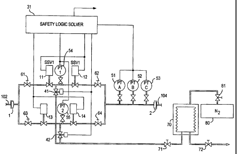
Referring to FIG. 1, a high integrity protection system (HIPS) 10 is installed
in
proximity to a wellhead in a piping system to convey a pressurized fluid
product, such as oil or
gas, from the wellhead 102 to a remote host location via pipeline 104. The
HIPS has an
inlet I connected to the wellhead piping 102 and an outlet 2 connected to
piping system 104
through which the liquid product enters and exits the HIPS 10. The HIPS is
preferably
skid-mounted for delivery to the site of the wellhead and is provided with
appropriate flanges
and adapters, if necessary, for attachment to the inlet and outlet to the oil
field
piping.
Two sets of surface safety valves (SSVs) II, 12 and 13, 14 are in fluid
communication with the inlet 1 and the outlet 2 are thereby operable as a
flowline for the
fluid product. Each set of SSVs, identified and referred to as SSV-1 and SSV-
2, has two
SSVs 11-12 and 13-14, respectively, which are connected in series. The SSVs
close
automatically in the absence of power being supplied to them and are
maintained in an open
position by conventional hydraulically or electrically powered actuators to
protect the
downstream piping system 104 from abnormal operational conditions.
Two vent control valves (VCVs) 41, 42 are connected to the piping intermediate
the
two set of SSVs 11, 12 and 13, 14, respectively, and are in fluid
communication with a vent
line 106. The vent line 106 is in fluid communication with a fluid reservoir
70 that serves
as a closed collection system tank. Alternatively, the vent line can be routed
to a burn pit (not
shown) near the well site. The VCVs 41, 42 upon their opening can vent
pressurized fluid
7
CA 02756050 2011-10-20
between the two SSVs into the vent line 106. Valves 71,72 and 81 control
supply of hydraulic
pressure by the pressure reservoir via their opening and closing. When the
valve 81 is
opened, pressurized nitrogen from the tank 80 forces fluid out of the
reservoir 70, either into
the HIPS pipeline or via valve 72 for alternate use or disposed. The VCVs 41,
42 vent
pressurized fluid from between the two SSVs into the vent line upon their
opening. Pressure
sensing transmitters 54, 55 are located between the respective SSVs to
determine the flowline
pressure between the two SSVs. Multiple pressure sensing transmitters can
optionally be
installed at locations 54 and 55 to assure reliability and as back-ups to the
test
system.
Pressure sensing transmitters 51, 52, 53 are installed upstream of the outlet
2 to
monitor the flowline pressure exiting the HIPS from outlet 2. The three
transmitters are
monitored by the safety logic solver 31. If any two of three transmitters 51-
53 sense a
pressure rise above a predetermined threshold value, the logic solver 31
automatically
shuts in the well via the SSVs 11-14, thereby protecting the downstream
pipeline from
excessive pressure.
A safety logic solver 31, which is preferably a software module preprogrammed
in a
computer or the like, is in communication with the SSVs 11-14, VCVs 41, 42,
and pressure
sensing transmitters 51-55 via a hard-wired connection or by wireless
transmitters. The
safety logic solver 31 produces and transmits signals to control the operation
of the SSVs 11 - -
14 and VCVs 41, 42. The control is performed based on pressure data from the
pressure
sensing transmitters 51-55.
Manual valves 61-64 are installed between inlet 1 and outlet 2 and SSVs 11-14
to
isolate the two sets of SSVs 11-14 from the piping system in case of an
emergency and also so
that the system can be shut down manually for repair and/or replacement of any
of its
components. All valves are operated by conventional valve actuators (not
shown) such as
those that are well known to art. The valve actuators and pressure
transmitters 51-55 have
self-diagnostic capabilities and communicate any faults to the safety logic
solver 31 that are
detected.
The method for conducting the shut-off test and full-stroke test in accordance
with
the invention will be described with reference to FIG. 2. Before the
commencement of the test,
a safety check of the HIPS flowline is made. If the flowline pressure exceeds
a predetermined
threshold level, all SSVs are closed. (S20) Otherwise, the first set of SSVs
11, 12 are closed and the second set of SSVs 13, 14 are closed. (S30)
8
CA 02756050 2011-10-20
The first set of SSVs 11, 12 are then opened to prepare for a test of the
second set of
SSVs 13, 14. (S 40) It is determined whether the first set of SSVs 11, 12
which are used as a
flowline during the shut-off test of the second set of SSVs 13, 14 are fully
opened. (S50) If
the first set of SSVs 11, 12 are not fully opened, an alarm signal is actuated
and the test is
terminated (S60). If the first set of SSVs 11, 12 are fully opened, the second
set of SSVs 13,
14 are closed. (S70) The full closing of the SSVs 13, 14 to be tested are
checked for the
preparation of the tight shut-off test. (S80) If the SSVs 13, 14 are not fully
closed, an alarm
signal is actuated (S90) and the test is terminated.
If the SSVs 13, 14 are fully closed, the tight shut-off test of the SSVs 13,
14 is
initiated. The VCV 42 located intermediate the second set of SSVs 13, 14 is
opened to reduce
the pressure between the SSVs 13, 14 to a stable value (Si 00).
The VCV 42 is then closed and the pressure sealing of VCV 42 is checked.
(S110) If
the VCV 42 is not fully closed, or the valve is leaking so that pressure
continues to drop in
the vented section of pipe between the valves, an alarm signal is actuated
(S120) and
appropriate remedial action is taken. If the VCV 42 is fully closed, the
pressure between the
SSVs 13, 14 is measured. (S130) The pressure between the SSVs 13, 14 continues
to be
monitored by the pressure transmitter 55 and the result is sent to the safety
logic solver 31
during the tight shut-off test up to the end of the tight shut-off test
period. (S140)
The data obtained during the tight shut-off test is graphically represented
for two
different scenarios in FIG. 3. When the VCV 42 is opened, the pressure between
the SSVs 13,
14 drops from a normal operating pressure to a lower pressure and the VCV 42
is fully closed.
If the pressure between SSVs 13, 14 rises, that is deemed to be evidence that
there is leakage
in one or both of SSVs 13, 14. Since some minimal amount of leakage may be
acceptable, it
must be determined whether a pressure increase, or the rate of pressure
increase, exceeds a
predetermined threshold level during or after the period of the tight shut-off
test. (S150) If
during the test period, the pressure rises above the threshold level, it
indicates a failure in the
ability of the SSVs 13, 14 to seat completely and an alarm signal is actuated
by the safety
logic solver 31 which notifies of the failure of the tight shut-off test of
the SSVs 13, 14.
(S160). If during the test period, the pressure increase does not exceed the
threshold level,
the second set of SSVs 13, 14 pass the tight shut-off test. The first set of
SSVs 11, 12, were
in an open position providing a flowpath for production during the tight shut-
off testing of
SSVs 13, 14. (S170) To complete the system functional testing, the second set
of SSVs 13,
14, which passed the tight shut-off test, are opened again and used as a
flowline. (S180)
9
CA 02756050 2011-10-20
As will be apparent from the above description, the first set of SSVs 11, 12
is tested
using substantially the same methodology.
The present invention enables the HIPS to operate continuously as a flowline
while a
tight shut-off and a full-stroke test is performed, and while any necessary
protective action can
be taken. The automatic operation by the safety logic solver assures that
emergency shut-off
conditions will be carried out, even during a test. A record of the test is
stored and can be
recovered later or displayed electronically and/or in printed graphic form or
as tabulated data.
Although various embodiments that incorporate the teachings of the present
invention
have been shown and described in detail, other and varied embodiments will be
apparent to those of ordinary skill in the art and the scope of the invention
is to be
determined by the claims that follow.