Note: Descriptions are shown in the official language in which they were submitted.
CA 02756051 2013-07-09
FILM-TAIL SEALING SYSTEM AND METHOD FOR WRAPPING APPARATUS
BACKGROUND OF THE INVENTION
[0002] The present invention relates to a wrapping apparatus and more
particularly to a wrapping material tail clamp, cut, and sealing system.
[0003] Many types of items are packaged in roll or coil form. For
example, steel and aluminum sheet are often coiled for storage, transport, and
handling.
Such coils can be up to five to seven feet in diameter.
[0004] In order to protect and preserve the appearance of the steel or
aluminum, the coils are typically wrapped with protective material in the form
of a film.
Such a film can be a single wrap of, for example, a low density polyethylene
stretch film.
The wrap can also include a fabric or other woven or non-woven material
wrapped along
with the polyethylene film.
[0005] One known machine for carrying out the wrapping process uses a
specifically shaped track to carry a film dispensing shuttle through the eye
of the coil,
while the coil is slowly rotated on its axis on a set of block rollers. The
complete body of
the coil is effectively sealed by a cocoon of stretch film.
[0006] Generally, the machine has a heavy-duty, generally oval shaped
track that provides the guide for the film-dispensing shuttle that traVels
around the inside
of the track. The track has a hinged end section or track arm that pivots
upwardly to open
the track so that a lower portion of the track can be moved into the eye of
the coil. The
track is adjustable in the vertical plane to accommodate different coil
diameters.
[0007] The track is typically movable on rails to advance into the eye
of
the coil. The machine can also be movable transverse to the direction of the
track. Such
a machine is commercially available from ITW Fleetwood-Signode of Glenview,
Illinois,
CA 02756051 2011 09 20
WO 2010/120709 PCT/US2010/030797
under the name CoilMaster. One such wrapping system is described in Albert, et
al.
published U.S. Patent application, US Publication No. 2008-0168643, which
disclosure is
incorporated herein by reference.
[0008] The film dispensing shuttle includes one or more tractors and
trailers that are designed to drive themselves around the track. The film is
provided on
the shuttle in rolls that have a finite amount of material wound thereon and
as such
require periodic replacement. Rolls may have to be replaced during the winding
of a coil,
or, conversely, a coil wrapping may be completed with film remaining on a
roll. In either
scenario, there are times when the film may have to be clamped, cut and sealed
during the
wrapping operation. To prevent the "tail" of the film from hanging from the
coil, in
known operations the tail is manually tucked into the wound film to prevent
the tail from
interfering with movement of the shuttle and to prevent unwrapping of the
film. Other
devices are known that seal the tail to the coil. While this may be effective,
there is the
opportunity for the film to become loose, thus compromising the integrity of
the wrap.
[0009] Accordingly, there is a need for a system and method for clamping,
cutting, and sealing the tail of the film. Desirably, such a system can effect
this operation
while a coil is on the wrapping machine. More desirably, such a system and
method
secures the film tail coming from the shuttle and prevents the film from
slipping and
unwrapping from the coil. More desirably still, such a system and method are
used to
clamp the film between itself and the shuttles, seal the film to the coil, and
cut the film
between the coil and itself. This holds the film (from the shuttles) at the
end of the
wrapping cycle to reduce the time and labor required to assure that a
subsequent
wrapping operation is carried out without undue labor.
BRIEF SUMMARY OF THE INVENTION
[0010] A film-tail clamp, cut, and seal system is configured for use in a
wrapping apparatus for wrapping an associated item. The wrapping apparatus has
an oval
track vertically oriented and openable to move into and out of the associated
item. The
wrapping apparatus includes a shuttle configured for movement along an inner
periphery
of the track. A wrapping material, such as a film, is dispensed from the
shuttle for
wrapping around the item.
2
CA 02756051 2013-07-09
[0011] The film-tail clamp, cut, and seal system of the wrapping
apparatus includes a clamp arm that is movable into and out of a plane defined
by the
film being wrapped around the item. The clamp arm also has a sealing element
for
contacting and sealing a free-end portion of the film onto a portion of the
film
wrapped around the item. The clamp arm includes a clamp for securing the film
when the free-end of the film is sealed onto the portion of the film already
wrapped
around the item. The clamp also includes a cutter for cutting the free-end
portion of
the film from the portion sealed onto the film wrapped around the item. The
clamp
secures the film for a subsequent coil wrapping operation.
[0012] A second carriage is present for moving the clamp arm
vertically toward and away from the item, within or parallel to the plane
defined by
the film being wrapped around the item. In addition, a third carriage may move
the
clamp arm horizontally toward and away from the item, within or parallel to
the plane
defined by the film being wrapped around the item.
[0012A1 In one broad aspect, the invention pertains to a film-tail-
clamp, cut, and seal system for use in a wrapping apparatus for wrapping an
associated item, the wrapping apparatus having an oval track vertically
oriented and
openable to move the track into and out of the associated item. The wrapping
apparatus includes a shuttle configured for movement along an inner periphery
of the
track and has a wrapping material dispensed therefrom for wrapping around the
item.
The film-tail clamp and seal system comprises a clamp arm movable into a plane
defined by the wrapping material being wrapped around the item when the
wrapping
material is being clamped, cut and sealed and out of the plane defined by the
wrapping material being wrapped around the item when the item is being
wrapped,
the clamp arm having a sealing element for contacting and sealing a free end
portion
of the wrapping material onto a portion of the wrapping material wrapped
around the
item. The clamp arm has a clamp for securing the wrapping material when the
wrapping material is sealed onto the portion of the wrapping material and the
clamp
arm has a cutter for cutting the free end portion of the wrapping material
from the
portion sealed onto the wrapping material wrapped around the item. A first
carriage
3
CA 02756051 2013-07-09
=
for moving the clamp into and out of the plane is defined by the wrapping
material
being wrapped around the item, and a second carriage for moving the clamp arm
toward and away from the item in a first direction within or parallel to the
plane is
defined by the wrapping material being wrapped around the item, the first and
second
carriages being movable perpendicular to one another.
[0012B] In a further aspect, the invention provides a wrapping
apparatus of the type for wrapping an associated item, the wrapping apparatus
having
an oval track vertically oriented and openable to move into and out of the
associated
item. The wrapping apparatus includes a shuttle configured for movement along
an
inner periphery of the track and has a wrapping material dispensed therefrom
for
wrapping around the item, the wrapping apparatus including a film-tail clamp,
cut,
and seal system. The film-tail clamp, cut, and seal system comprises a clamp
arm
movable into a plane defined by the wrapping material being wrapped around the
item
when the wrapping material is being clamped, cut and sealed and out of the
plane
defined by the wrapping material being wrapped around the item when the item
is
being wrapped. The clamp arm has a sealing element for contacting and sealing
a
free end portion of the wrapping material onto a portion of the wrapping
material
wrapped around the item, the clamp arm having a clamp for securing the
wrapping
material when the wrapping material is sealed onto the portion of the wrapping
material and the clamp arm has a cutter for cutting the free end portion of
the
wrapping material from the portion sealed onto the wrapping material wrapped
around
the item. A first carriage for moving the clamp arm into and out of the plane
is
defined by the wrapping material being wrapped around the item, and a second
carriage for moving the clamp arm vertically toward and away from the item
within
or parallel to the plane is defined by the wrapping material being wrapped
around the
item, the first and second carriages being movable perpendicular to one
another.
3a
CA 02756051 2013-07-09
BRIEF DESCRIPTION OF THE SEVERAL VIEWS OF THE DRAWINGS
[0013] The benefits and advantages of the present invention will
become more readily apparent to those of ordinary skill in the relevant art
after
reviewing the following detailed description and accompanying drawings,
wherein:
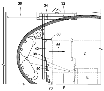
[0014] FIG. 1 is a side view of a wrapping apparatus having a film-
tail sealing system in accordance with the principles of the present
invention, the
sealing system track shown in place in a center of a coil;
[0015] FIG. 2 is an enlarged, partial view of the top of the
apparatus
of FIG. 1;
[0016] FIG. 3 is a top view of the wrapping apparatus showing the
location of the sealing system;
[0017] FIg. 4 is a view longitudinally along the wrapping system
into
the col on the wrapping machine, as viewed from the left-hand side of FIG. 1;
[0018] FIG. 5 is a view similar to FIG. 4 showing the wrapping
system arm in the extended position;
[0019] FIG. 6 is a top view of the arm of FIG. 5; and
3b
CA 02756051 2011-09-20
WO 2010/120709
PCT/US2010/030797
[0020] FIG. 7 is a view of the arm similar to FIG. 5 showing the
clamp
jaw in phantom in the open position and in solid lines in the closed position.
DESCRIPTION OF THE INVENTION
[0021] While the present invention is susceptible of embodiment in
various forms, there is shown in the figures and will hereinafter be described
a presently
preferred embodiment with the understanding that the present disclosure is to
be
considered an exemplification of the invention and is not intended to limit
the invention
to the specific embodiment illustrated.
[0022] Referring to the figures and in particular to FIG. 1, there
is shown
a wrapping apparatus or machine 10 having a film-tail sealing system 12 and
carrying out
a method for film-tail sealing embodying the principles of the present
invention.
[0023] The machine 10 includes a track 14 having a generally oval
shape.
A lower portion 16 of the track 14 is cantilevered when a track arm 18 is
open. An end
(or the track arm 18) of the oval is hinged opposite of the base (with the
hinge 20 at about
the top of the track 14) to permit the track 14 to be opened to move the track
into and out
of the eye E of the coil C. When closed, the track arm 18 aligns with the
lower portion
16 of the track 14. The inside or inner periphery 15 of the track 14, thus,
defines the
substantially continuous track 14. The track 14 moves up and down to
accommodate
coils C of different diameters.
[0024] A shuttle 22 is configured for movement along the inner
periphery
15 of the track 14 in the direction indicated by the arrow at 24. The shuttle
22 includes a
drive or tractor 26, and one or more film F dispensing cars or trailers 28
that are pulled
along by the tractor 26. The trailers 28 can dispense polymer films, fabric or
like
wrapping member, collectively referred to as film or films F.
[0025] The machine 10 can include a change system (not shown) to
permit removing the shuttle 22 from the track 14 and replacing the shuttle 22
with a
ready, stand-by or replacement shuttle 22 with the track 14 in place in the
eye E of the
coil C. Such a change system is disclosed in the aforementioned published
patent
application to Albert et al., US Pub. No. 2008-0168643.
4
CA 02756051 2011-09-20
WO 2010/120709 PCT/US2010/030797
[0026] During coil C change-out, it is necessary to cut the film F and to
clamp the film F so as to not "lose" the tail 29 of the film F that is
attached to the shuttle
22 when preparing to commence a subsequent wrapping cycle. In addition, a
"second"
tail (from the coil C) is desirably sealed to the coil C to prevent the film F
from
unwrapping from the coil C. The present film-tail sealing system 12 effects
the cutting,
clamping and sealing operations. As illustrated in FIG. 3, the system 12 is
mounted to
the wrapping machine 10 at a side 30 of the machine 10. A frame 32 is mounted
at about
the top rail of the machine 10. A first main carriage 34 is mounted to the
frame 32 to
move horizontally along the frame 32 toward and away from the coil C (in the
same
direction of travel as the shuttle). Movement is effected by a main carriage
cylinder 36
(such as a hydraulic cylinder). Other drives can be used as will be recognized
by those
skilled in the art.
[0027] The main or first carriage 34 carries a vertical track 38 and a
second (or vertical) carriage 40 moves vertically (up and down) on the
vertical track 38.
Movement of the vertical carriage 40 is effected by a vertical carriage
cylinder 42, such
as a hydraulic cylinder, but again, other drives can be used as will be
recognized by those
skilled in the art.
[0028] A clamp track 44 is carried on the vertical (second) carriage 40 and
a clamp carriage (also referred to herein as a "third carriage") 46 moves
horizontally
along the clamp track 44 into and out of the plane P14 (see FIG. 3) of the
shuttle track 14
(as viewed from the perspective of FIG. 1, into and out of the plane of the
figure).
Essentially, the clamp carriage 46 moves into and out of the path of the film
F as it wraps
around the coil C. Movement of the clamp carriage 46 is effected by a clamp
carriage
cylinder 50, such as a hydraulic cylinder, but again, other drives can be used
as will be
recognized by those skilled in the art.
[0029] Referring to FIG. 7, the clamp carriage 46 is formed as a jaw 52
and has a clamp/cutter/sealer assembly 54 mounted thereto. A portion of the
clamp/cutter/sealer assembly 54 is carried on a clamp arm 56 that pivots as
seen in FIG. 7
between an open state (the clamp arm 56 pivoted up) and a closed or clamped
state (the
clamp arm 56 pivoted down). Movement of the clamp arm 56 is effected by a
clamp arm
CA 02756051 2011 09 20
WO 2010/120709 PCT/US2010/030797
cylinder 58, such as a hydraulic cylinder, but other drives can be used as
will be
recognized by those skilled in the art.
[0030] A blade 60 within the clamp arm 56 is configured to move (in a
reciprocating motion) toward the clamped film F, to cut the film F. Blade 60
movement
is effected by blade drive cylinders 62, such as a pneumatic cylinders or the
like. Other
drives can be used as will be recognized by those skilled in the art.
[0031] A sealing bar 64 is mounted to the clamp/cutter/sealer assembly 54
adjacent to the clamp arm 56. The sealing bar 64 is an electric heater element
that is used
to heat (and seal) the film F onto itself.
[0032] A typical operation sequence is as follow. A wrapping operation
has completed ¨ the shuttles 22 are at a home position (as seen in FIG. 1) and
the film F
is still attached to the shuttles 22 and coil C. The tail sealing system 12 is
in the home
position with the first main carriage 34 retracted (moved toward the shuttles
22), the
vertical carriage 40 lowered down and the clamp carriage 46 retracted (away
from the
coil C). The clamp arm 56 is in the open position.
[0033] The clamp carriage 46 moves inward toward the center of the coil
C (as indicated by the arrow at 72) so that the film F is disposed within the
clamp jaw
(with the jaw open). The first main carriage cylinder 36 is actuated to move
the first
main carriage 34 (and thus the clamp arm 56) toward the coil C as indicated by
the arrow
at 66. A sensor 68, such as a photoelectric proximity sensor, located on the
clamp/cutter/sealer assembly 54 (in a present embodiment located on the
vertical track
38) senses when the clamp arm 56 is near to the coil C edge. This also
positions the
sealing bar 64 at about the edge of the coil C and a limit switch 70 just
inside the bore of
the coil C (the limit switch 70 is just below the sealing bar 64).
[0034] The vertical carriage 40 (the second carriage) moves up until the
limit switch contacts the inside edge of the coil C. This positions the
sealing bar 64 at the
proper location for sealing.
[0035] The first main carriage 34 moves inward toward the coil C so that
the sealing bar 64 contacts the coil C (actually contacts the film F on the
coil C) and
compresses the film-tail 29 on the film F (that is wrapped around the coil C).
A pressure
transducer (not shown) can be used to determine that a proper pressure is
achieved. The
6
CA 02756051 2013-07-09
clamp arm 56 then closes to hold the film F in the clamp arm 56 and the
sealing bar
64 is actuated (current is supplied to the sealing bar 64) to seal the film-
tail 29 to the
film F that is wrapped around the coil C. This seals the tail 29 to the coil
C.
[0036] Following sealing of the tail 29 to the coil C, the cutter
cylinders 62 are actuated to cut the film-tail 29 from the coil C. The blade
60 is
positioned between the sealing bar 64 and the clamp arm 56 so that the wrapped
coil
C is then separable from clamp arm 56, but the film F (coming from the
shuttles 22)
remains clamped in the clamp arm 56.
[0037] The main carriage 34 retracts (moves away from the coil C),
the vertical carriage 40 lowers down and the clamp carriage 46 moves the plane
of the
machine track 14. The coil C can then be removed from the wrapping machine 10
and a new coil C placed in the machine 10 for wrapping. It will be appreciated
that
the film F has remained clamped in the clamp arm 56, and thus the wrapping
machine
can commence wrapping a new coil C, with the film F secured, to effect proper
wrapping of the coil C. Because the film F is held by the clamp arm 56, the
film F
will not slip from the coil C as wrapping commences.
[0038] The advantages of the present film-tail clamp, cut, and seal
system 12 will be appreciated by those skilled in the art. The seal system 12
secures
the free or tail end of the protective film F covering for a coil C of
material, such as
aluminum or steel sheet, while the coil C is on the wrapping machine 10. The
present system 12 prevents the film F from slipping and unwrapping from the
coil C,
effectively clamping the film F between the clamp arm 56 and the shuttle 22,
sealing
the film F to the coil C, and cutting the film F between the coil C and the
clamp arm
56. Holding the film F (from the shuttle 22) at the end of the wrapping cycle
reduces
the time and labor required to assure that a subsequent wrapping operation is
carried
out without undue labor.
[0039] In the present disclosure, the words "a" or "an" are to be
taken to include both the singular and the plural. Conversely, any reference
to plural
items shall, where appropriate, include the singular.
7
CA 02756051 2013-07-09
[0040] The scope of
the claims should not be limited by the preferred
embodiments set forth in the description, but should be given the broadest
interpretation consistent with the description as a whole.
8