Note: Descriptions are shown in the official language in which they were submitted.
CA 02756242 2011-10-25
1
AN APPARATUS FOR REDUCING WEB FEED RATE VARIATIONS INDUCED BY
PARENT ROLL GEOMETRY VARIATIONS
FIELD OF THE INVENTION
The present invention relates generally to an apparatus for overcoming
problems
associated with geometrically induced web feed rate variations during the
unwinding of out-
of-round parent rolls. More particularly, the present invention relates to an
apparatus for
reducing the tension variations associated with web feed rate changes that are
induced by
parent roll geometry variations to minimize oscillation while maximizing
operating speed
i o throughout the entire unwinding cycle.
BACKGROUND OF THE INVENTION
In the papermaking industry, it is generally known that paper to be converted
into a
consumer product such as paper towels, bath tissue, facial tissue, and the
like is initially
manufactured and wound into large rolls. By way of example only, these rolls,
commonly
1s known as parent rolls, may be on the order of 10 feet in diameter and 100
inches across and
generally comprise a suitable paper wound on a core. In the usual case, a
paper converting
facility will have on hand a sufficient inventory of parent rolls to be able
to meet the
expected demand for the paper conversion as the paper product(s) are being
manufactured.
Because of the soft nature of the paper used to manufacture paper towels, bath
tissue,
20 facial tissue, and the like, it is common for parent rolls to become out-of-
round. Not only the
soft nature of the paper, but also the physical size of the parent rolls, the
length of time
during which the parent rolls are stored, and the fact that roll grabbers used
to transport
parent rolls grab them about their circumference can contribute to this
problem. As a result,
by the time many parent rolls are placed on an unwind stand they have changed
from the
25 desired cylindrical shape to an out-of-round shape.
In extreme cases, the parent rolls can become oblong or generally egg-shaped.
But,
even when the parent roll is are only slightly out-of-round, there are
considerable problems.
In an ideal case with a perfectly round parent roll, the feed rate of a web
material coming off
of a rotating parent roll can be equal to the driving speed of a surface
driven parent roll.
30 However, with an out-of-round parent roll the feed rate can likely vary
from the driving
CA 02756242 2011-10-25
2
speed of a surface drive parent roll depending upon the radius at the web
takeoff point at any
moment in time.
With regard to the foregoing, it will be appreciated that the described
condition
assumes that the rotational speed of the parent roll remains substantially
constant throughout
any particular rotational cycle of the parent roll.
If the rotational speed remains substantially constant, the feed rate of a web
material
coming off of an out-of-round parent roll will necessarily vary during any
particular
rotational cycle depending upon the degree to which the parent roll is out-of-
round. In
practice, however, parent rolls are surface driven which means that if the
radius at the drive
i o point changes, the rotational speed can also change generally causing
variations in the feed
rate. Since the paper converting equipment downstream of the unwind stand is
generally
designed to operate based upon the assumption that the feed rate of a web
material coming
off of a rotating parent roll will always be equal to the driving speed of the
parent roll, there
are problems created by web tension spikes and slackening.
is While a tension control system is typically associated with the equipment
used in a
paper converting facility, the rotational speed and the takeoff point radius
can be constantly
changing in nearly every case. At least to some extent, this change is
unaccounted for by
typical tension control systems. It can be dependent upon the degree to which
the parent roll
is out-of-round and can result in web feed rate variations and corresponding
tension spikes
20 and slackening.
With an out-of-round parent roll, the instantaneous feed rate of the web
material can
be dependent upon the relationship at any point in time of the radius at the
drive point and the
radius at the web takeoff point. Generally and theoretically, where the out-of-
round parent
roll is generally oblong or egg-shaped, there will be two generally
diametrically opposed
25 points where the radius of the roll is greatest. These two points will be
spaced approximately
90 from the corresponding generally diametrically opposed points where the
radius of a roll
is smallest. However, it is known that out-of-round parent rolls may not be
perfectly oblong
or elliptical but, rather, they may assume a somewhat flattened condition
resembling a flat
tire, or an oblong or egg-shape, or any other out-of-round shape depending
upon many
3o different factors.
CA 02756242 2011-10-25
3
Regardless of the exact shape of the parent roll, at least one point in the
rotation of the
parent roll exists where the relationship between the web take off point
radius and the parent
roll drive point radius that results in the minimum feed rate of paper to the
line. At this point,
the web tension can spike since the feed rate of the web material is at a
minimum and less
than what is expected by the paper converting equipment downstream of the
unwind stand.
Similarly, there can exist at least one point in the rotation of the parent
roll where the
relationship between the web take off point radius and the parent roll drive
point radius
results in the maximum feed rate of paper to the line. At this point, the web
tension can
slacken since the feed rate of the web material can be at a maximum and more
than what is
1 o expected by the paper converting equipment downstream of the unwind stand.
Since neither
condition is conducive to efficiently operating paper converting equipment for
manufacturing
paper products such as paper towels, bath tissue and the like, and a spike in
the web tension
can even result in a break in the web material requiring a paper converting
line to be shut
down, there clearly is a need to overcome this problem.
In particular, the fact that out-of-round parent rolls create variable web
feed rates and
corresponding web tension spikes and web tension slackening has required that
the unwind
stand and associated paper converting equipment operating downstream thereof
be run at a
slower speed in many instances thereby creating an adverse impact on
manufacturing
efficiency.
While various efforts have been made in the past to overcome one or more of
the
foregoing problems with out-of-round parent rolls, there has remained a need
to successfully
address the problems presented by web feed rate variations and corresponding
web tension
spikes and web tension slackening.
SUMMARY OF THE INVENTION
While it is known to manufacture products from a web material such as paper
towels,
bath tissue, facial tissue, and the like, it has remained to provide an
apparatus for reducing
feed rate variations in the web material when unwinding a parent roll.
Embodiments of the
present disclosure described in detail herein provides an apparatus having
improved features
which result in multiple advantages including enhanced reliability and lower
manufacturing
costs. Such an apparatus not only overcomes problems with currently utilized
conventional
CA 02756242 2011-10-25
4
manufacturing operations, but it also makes it possible to minimize wasted
materials and
resources associated with such manufacturing operations.
In certain embodiments, the apparatus can reduce feed rate variations in a web
material when unwinding a parent roll to transport the web material away from
the parent roll
at a web takeoff point. The apparatus comprises a rotational position and
speed determining
device associated with the parent roll for determining the rotational position
and speed of the
parent roll and a drive system associated with a driving mechanism for
imparting rotational
movement to the parent roll on the unwind stand. The drive system also causes
the driving
mechanism to drive the parent roll at a drive point which is located on the
outer surface of the
parent roll. The apparatus further comprises a measuring device associated
with the unwind
stand for measuring the radius of the parent roll on the unwind stand and a
logic device for
generating for the drive system both an ideal speed reference signal
corresponding to an ideal
parent roll rotation speed for a round parent roll and a corrected speed
reference signal. The
ideal and corrected speed reference signals can be used to drive the parent
roll at a driving
t5 speed and at a location on the outer surface either coincident with or
spaced from the web
takeoff point. The ideal speed reference signal is based at least upon
operator input and the
corrected speed reference signal is generated for adjusting the driving speed
of the drive
system to a corrected driving speed.
To adjust the driving speed of the driving mechanism, the logic device is
associated
with: i) the rotational position and speed determining device for receiving
the rotational
position and speed of the parent roll, ii) the drive system for initially
controlling the speed of
the driving mechanism based upon the ideal speed reference signal, and iii)
the measuring
device for receiving the measured radius for the parent roll.
The logic device divides the parent roll, which has a core plug mounted on a
shaft
defining a longitudinal axis of the parent roll, into a plurality of angular
sectors disposed
about the longitudinal axis and correlates each of the sectors at the web
takeoff point with a
corresponding one of the sectors at the drive point. The logic device is
initially operable to
control the drive system such that the driving mechanism drives the parent
roll at the drive
point at a driving speed based upon the ideal speed reference signal, and it
receives data from
the rotational position and speed determining device to determine an
instantaneous rotational
CA 02756242 2011-10-25
speed for each of the sectors as the parent roll is being driven, for example,
by a motor-
driven belt on the outer surface thereof. The logic device: i) calculates the
radius at the drive
point for each of the sectors as a function of the driving and rotational
speeds for each of the
sectors, and ii) determines an ideal drive point radius by determining an
average for the
5 calculated drive point radii for all of the sectors.
From the foregoing, the logic device calculates a drive point correction
factor for each
of the sectors as a function of the calculated drive point radius and the
ideal drive point
radius.
The measuring device measures the radius at or near the web takeoff point of
the
to parent roll for each of the sectors as the parent roll is being driven at
the drive point. The
logic device calculates an ideal web takeoff point radii for all of the
sectors and calculates a
web takeoff point correction factor for the radius at the web takeoff point
for each of the
sectors where the web takeoff point correction factor is a function of the
ideal and measured
web takeoff point radius for each of the sectors.
From the foregoing, the logic device calculates a total.correction factor for
each of the
sectors as a function of the drive point correction factor and the web takeoff
point correction
factor.
The logic device corrects the driving speed of the parent roll on a sector by
sector
basis using the ideal speed reference signal. The ideal speed reference signal
is initially used
to control the parent roll rotation speed based upon operator input (assuming
a perfectly
round parent roll) as well as other factors, such as tension control system
feedback and ramp
generating algorithms. The ideal speed reference signal is multiplied by the
total correction
factor for each sector of the parent roll to generate a corrected speed
reference signal for each
sector. The corrected speed reference signal is calculated on the fly (and not
stored) based
upon the ideal speed reference signal from moment to moment, taking into
account factors
such as tension control system feedback and ramp generating algorithms.
Finally, the
corrected speed reference signal is used to adjust the driving speed of the
parent roll for each
sector to the corrected driving speed.
Adjusting the driving speed of the parent roll in this manner causes the web
feed rate
of the parent roll to at least approximate the web feed rate of an ideal
(perfectly round) parent
CA 02756242 2011-10-25
6
roll on a continuous basis during the unwinding of a web material from a
parent roll. As a
result, feed rate variations in the web material at the web takeoff point are
reduced or
eliminated and, thus, web tension spikes and slackening associated with radial
deviations
from a perfectly round parent roll are minimized or eliminated.
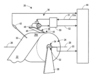
BRIEF DESCRIPTION OF THE DRAWINGS
Fig. 1 is a schematic view of an apparatus for reducing feed rate variations
in a web
material when unwinding a parent roll in accordance with the present
disclosure;
Fig. 2 is diagram illustrating equation concepts involving the web flow feed
rate,
Rate,, the rotational speed, fl,. and the web takeoff point radius R,,,, for a
parent roll;
Fig. 3 is a diagram illustrating equation concepts involving the rotational
speed, C2,,
the driving speed, Mõ and the drive point radius, Rdp, for a parent roll;
Fig. 4 is a diagram illustrating equation concepts involving the web flow feed
rate,
Rateõ the web takeoff point radius, R4,, and the web drive point radius, Rdp,
for a parent roll;
Fig. 5 is a diagram illustrating equation concepts involving the web flow feed
rate,
Rate,, and the driving speed, M,, for the case where the parent roll is
perfectly round;
Fig. 6 is a diagram illustrating an out-of-round parent roll having a major
axis, R1,
and a minor axis, R2, which are approximately 90 degrees out of phase;
Fig. 7 is a diagram illustrating an out-of-round parent roll having a major
axis, R1,
orthogonal to the drive point and a minor axis, R2, orthogonal to the web
takeoff point;
Fig. 8 is a diagram illustrating an out-of-round parent roll having a minor
axis, R2,
orthogonal to the drive point and a major axis, R1, orthogonal to the web
takeoff point;
Fig. 9 is a diagram illustrating an out-of-round parent roll that is generally
egg shaped
having unequal major axes and unequal minor axes;
Fig. 10 is a diagram illustrating the out-of-round parent roll of Fig. 9 which
has been
divided into four sectors, 1-4;
Fig. I 1 is a diagram illustrating the out-of-round parent roll of Fig. 9 with
the larger
of the minor axes, R1, at the drive point; and
Fig. 12 is an example of a data table illustrating four actual angular sectors
each
divided into eight virtual sectors for smoothing transitions.
DETAILED DESCRIPTION OF THE INVENTION
CA 02756242 2011-10-25
7
In the manufacture of web material products including paper products such as
paper
towels, bath tissue, facial tissue, and the like, the web material which is to
be converted into
such products is initially manufactured on large parent rolls and placed on
unwind stands.
The embodiments described in detail below provide non-limiting examples of an
apparatus
for reducing feed rate variations in a web material when unwinding a parent
roll to transport
the web material from the parent roll at a web takeoff point. In particular,
the embodiments
described below provide an apparatus which takes into account any out-of-round
characteristics of the parent roll and makes appropriate adjustments to reduce
web feed rate
variations.
With regard to these non-limiting examples, the described apparatus makes it
possible
to effectively and efficiently operate an unwind stand as part of a paper
converting operation
at maximum operating speed without encountering any significant and/or
damaging
deviations in the tension of the web material as it leaves an out-of-round
parent roll at the
web takeoff point.
is In order to understand the apparatus making it possible to reduce feed rate
variations
in a web material as it is being transported away from an out-of-round parent
roll, it is
instructive to consider certain calculations, compare an ideal parent roll
case with an out-of-
round parent roll case, and describe the effects of out-of-round parent rolls
on the web feed
rate and web material tension in addition to describing the apparatus itself.
Referring to Fig. 1, the reference numeral 20 designates generally an
apparatus for
reducing feed rate variations in a web material 22 when unwinding a parent
roll 24 having a
longitudinal axis 26 on an unwind stand 28 to transport the web material 22
away from the
parent roll 24 at a web takeoff point 30. The apparatus 20 comprises a
rotational position and
speed determining device 32 such as a rotary or shaft optical encoder,
resolver, a synchro, a
rotary variable differential transformer (RVTD), any similar device, and
combinations
thereof, all of which are known to be capable of determining rotational speed
and position,
can be used to determine the rotational speed and position at the parent roll
core plug.
The apparatus 20 also preferably includes a drive system generally designated
36 to
be associated with a driving mechanism 38 for imparting rotational movement to
the parent
3o roll 24 on the unwind stand 28. The drive system 36 causes the driving
mechanism 38 to
CA 02756242 2011-10-25
8
drive the parent roll 24 at a drive point 40 which is located on the outer
surface 24a of the
parent roll 24. The apparatus 20 preferably further comprises a measuring
device 42
associated with the unwind stand 28 for measuring the radius of the parent
roll 24 on the
unwind stand 28 and a logic device 44 for generating both an ideal speed
reference signal 51
and a corrected speed reference signal 51a for the drive system 36. In
particular, the ideal
speed reference signal 51 is based at least upon operator input and the
corrected speed
reference signal 51 a is generated for adjusting the driving speed of the
drive system 36 to a
corrected driving speed.
To adjust the driving speed of the driving mechanism 38, the logic device 44
is
associated with: i) the rotational position and speed determining device 32
for receiving the
rotational position and speed of the parent roll 24, ii) the drive system 36
for initially
controlling the speed of the driving mechanism 38 based upon the ideal speed
reference
signal 51, and iii) the measuring device 42 for receiving the measured radius
for the parent
roll 24.
is The logic device 44 divides the parent roll 24 into a plurality of angular
sectors (see
Fig. 9) disposed about the longitudinal axis 26 thereof and correlates each of
the sectors at
the web takeoff point 30 with a corresponding one of the sectors at the drive
point 40. The
logic device 44 is initially operable to control the drive system 36 such that
the driving
mechanism 38 drives the parent roll 24 at the drive point 40 at a driving
speed based upon the
ideal speed reference signal 51, and it receives data from the rotational
position and speed
determining device 32 which reports the rotational position and rotational
speed 53 of the
parent roll to determine which sector is presently approaching or is located
at the drive point
40 of the parent roll as the parent roll 24 is undergoing rotational movement.
The logic
device 44 calculates: i) the radius at the drive point 40 for each of the
sectors as a function of
the driving speed and the rotational speed and ii) an ideal drive point radius
by determining
an average for the calculated drive point radii for all of the sectors.
From the foregoing, the logic device 44 calculates a drive point correction
factor for
each of the sectors as a function of the calculated drive point radius and the
ideal drive point
radius.
CA 02756242 2011-10-25
9
The measuring device 42 measures the radius at or near the web takeoff point
30 of
the parent roll 24 for each of the sectors as the parent roll 24 is being
driven at the drive point
40. The logic device 44 calculates an ideal web takeoff point radius by
determining an
average for the measured web takeoff point radius for all sectors. The logic
device 44 then
s calculates a web takeoff point correction factor for each of the sectors as
a function of the
ideal web takeoff point radius and the measured web takeoff point radius.
From the foregoing, the logic device 44 calculates a total correction factor
for each of
the sectors as a function of the drive point correction factor and the web
takeoff point
correction factor.
to Following the calculation of the total correction factor for each sector,
the logic
device can multiply the ideal speed reference signal 51 for the drive system
36 by the total
correction factor for each sector as that sector arrives at or approaches the
drive point 40 to
establish the corrected speed reference signal for that sector. This corrected
speed reference
signal may cause the parent roll drive system 36 to vary its speed in such a
way as to
15 compensate for web feed rate variations, and hence tension variations in
the web material 22,
caused by radial deviations from a perfectly round parent roll.
In an exemplary non-limiting embodiment, the driving mechanism 38 for the
parent
roll 24 can comprise a motor-driven belt 46 in contact with the outer surface
24a of the
parent roll 24 (see Fig. 1). A motor 48 can be operatively associated with the
belt 46 in any
20 conventional manner as a part of the drive system 36 for controlling the
driving speed of the
belt 46. As will be appreciated, the motor 48 is capable of running at a speed
corresponding
to the ideal and corrected speed reference signals from the logic device 44
for adjusting the
driving speed.
More specifically, the motor 48 receives a signal for each of the sectors as
that sector
25 approaches or passes by the drive point 40 which serves as a command to the
motor 40 to
adjust the driving speed for each of the sectors when each of the sectors is
at the drive point
40 to a corrected driving speed based upon the corrected speed reference
signal for each of
the sectors.
In the exemplary non-limiting embodiment, the drive system 36 may comprise a
30 variable frequency drive (VFD), a DC drive (DC), or a servo amplifier (SA)
50 that receives
CA 02756242 2011-10-25
the speed reference signal 51 from the logic device 44. In either case, the
VFD, DC, or SA
50 is operatively associated with the motor 48 and serves to control the motor
48 which
preferably includes an integrated feedback device to cause the motor 48 to run
at a speed
corresponding to either the ideal speed reference signal 51 or corrected speed
reference
s signal. As will be appreciated, the VFD or SA 50 also serves to report the
speed at which the
motor 48 is actually running 52 to the logic device 44 for use in the
calculation of drive point
radii.
With regard to the motor 48 having the integrated feedback device, it may
advantageously comprise AC motors, DC motors, servo motors, combinations
thereof, and
i o the like.
As for other details of the exemplary non-limiting embodiment, the rotational
position
and speed determining device 32 may determine the rotational speed of the
parent roll 24 by
measuring the rotational speed of the shaft 34 of the parent roll 24. Still
referring to Fig. 1, it
will be appreciated that the measuring device 42 can advantageously comprise a
laser
positioned to measure the web takeoff point radius for each of the sectors at
or near the actual
web takeoff point. One skilled in the art will appreciate that the distance
reported from the
measuring device 42 to the parent roll surface should be subtracted from the
known distance
from the measuring device 42 to the center of the parent roll 24 to derive the
radius of the
parent roll 24. It will be understood that any conventional unwind stand 28 of
the type well
known and used in the industry to unwind web materials is suitable for use
with the present
invention.
With the foregoing understanding of the various components of the apparatus
20, it
is now useful to describe in detail the operation of the logic device 44 which
suitably
comprises a programmable logic device including the web feed rate calculation,
the ideal
parent roll case, the out-of-round parent roll case, the effects of out-of-
round parent rolls on
web feed rate and tension, and the solution to the problem provided by the
interaction of the
logic device 44 with the remainder of the apparatus 20.
WEB FEED RATE CALCULATION
The instantaneous feed rate of a web material 22 coming off of a rotating
parent roll
24 at any point in time, Rate,, can be represented as a function of at least
two variables. The
CA 02756242 2011-10-25
11
two most significant variables involved are the rotational speed, 52,, of the
parent roll 24 at
any given moment and the effective radius, R,p, of the parent roll 24 at the
web takeoff point
30 at that given moment. The instantaneous feed rate of the web material 22
may be
represented by the following equation:
Equation 1 Rate; = Q(27rR,p)
Where:
Rate, represents the instantaneous feed rate of the web material from the
parent roll
24
ci, represents the instantaneous rotational speed of a surface driven parent
roll 24
R,p represents the instantaneous radius of the parent roll 24 at the web
takeoff
point 30
Referring to Fig. 2, the concepts from Equation I can be better understood
since each
of the variables in the equation is diagrammatically illustrated.
Furthermore, the instantaneous rotational speed, Cl,, of a surface driven
parent roll 24
is a function of two variables. The two variables involved are the
instantaneous surface or
driving speed, M,, of the mechanism that is moving the parent roll 24 and the
instantaneous
radius of the parent roll 24 at the point or location at which the parent roll
24 is being driven,
Rdp. The instantaneous rotational speed may be represented by the following
equation:
Equation 2 S2, = M/(2irRdp)
Where:
Cl, represents the instantaneous rotational speed of a surface driven parent
roll 24
M, represents the instantaneous driving speed of the parent roll driving
mechanism 38
Rdp represents the instantaneous radius of the parent roll 24 at the drive
point 40
Referring to Fig. 3, the concepts from Equation 2 can be better understood
since each
of the variables in the equation is diagrammatically illustrated.
CA 02756242 2011-10-25
12
With regard to the instantaneous drive point radius, Rdp, it can be determined
from
Equation 2 by multiplying both sides of the equation by Rd"/S2; to give
Equation 2a below:
Equation 2a Rdp = MI-2n0,
Substituting M1i(2irRdp) for f2, in Equation 1 (based on Equation 2) results
in Equation
3 which relates the instantaneous feed rate, Rate;, of the web material from
the parent roll 24
to the instantaneous driving speed, Mt, of the parent roll driving mechanism
38, the
instantaneous radius, Rdp, of the parent roll 24 at the drive point 40, and
the instantaneous
1 o radius, Rtp, of the parent roll 24 at the web takeoff point 30:
Equation 3 Rate, = [Mt/(2xRdp)] x [27rR1p]
If Equation 3 is simplified by canceling out the 2ir factor in the numerator
and
denominator, the resulting Equation 4 becomes:
Equation 4 Ratei = M= x [Rp/Rdp]
Referring to Fig. 4, the concepts from Equation 4 can be better understood
since each
of the variables in the equation is diagrammatically illustrated.
IDEAL PARENT ROLL CASE
In the ideal parent roll case (see Fig. 5), the parent roll 24 on the unwind
stand is
perfectly round which results in the radii at all points about the outer
surface 24a being equal
and, as a consequence, the instantaneous radius, Rdp, of the parent roll 24 at
the drive point 40
is equal to the instantaneous radius, Rtp, of the parent roll 24 at the web
takeoff point 30. For
the ideal parent roll case, Rp = Rdp so, in Equation 4, it will be appreciated
that the equation
can simplify to Rate1 = M; , i.e., the instantaneous feed rate of the web
material from the
parent roll 24 can be equal to the instantaneous driving speed of the driving
mechanism 38 on
the outer surface 24a of the parent roll 24.
CA 02756242 2011-10-25
13
THE OUT-OF-ROUND PARENT ROLL CASE
In situations where the parent roll 24 that is introducing web material 22
into the
paper converting equipment is not perfectly round (see Figs. 6-8), the
differences between
Rdp and Rip should be taken into account. In practice, it is known that one
type of out-of-
round parent roll can be an "egg-shaped" parent roll (Fig. 6) characterized by
a major axis
and a minor axis typically disposed about 90 degrees out of phase. However,
the exact shape
of the parent roll 24 as well as the angular relationship of the major axes
and the minor axes
will be understood by one of skill in the art to vary from parent roll to
parent roll.
For purposes of illustration only, Fig. 7 is a diagram of an out-of-round
parent roll 24
having a major axis, R1, orthogonal to the drive point 40 and a minor axis,
R2, orthogonal to
the web takeoff point 30, and Fig. 8 is a diagram of an out-of-round parent
roll 24 having a
minor axis, R2, orthogonal to the drive point 40 and a major axis, R1,
orthogonal to the web
takeoff point 30.
EFFECTS OF OUT-OF-ROUND PARENT ROLLS ON WEB FEED RATE AND
TENSION
When the driving mechanism 38 on an unwind stand 28 is driving an out-of-round
parent roll 24, there may be a continuously varying feed rate of the web
material from the
parent roll 24. The varying web feed rates at the web takeoff point 30 may
typically reach a
maximum and a minimum in two different cases. To understand the concepts, it
is useful to
consider the web takeoff point 30 while assuming the parent roll drive point
40 and the web
takeoff point 30 are 90 degrees apart.
Case I is when the major axis of the parent roll 24, represented by R1 in
Figs. 6 and
7, is orthogonal to the drive point 40 of the parent roll 24 and the minor
axis of the parent roll
24, represented by R2 in Figs. 6 and 7, is orthogonal to the web takeoff point
30 of the parent
roll 24.
For illustrative purposes only, it may be assumed that the parent roll 24
started out
with the radii at all points about the outer surface 24a of the parent roll 24
equal to 100 units.
However, it may also be assumed that due to certain imperfections in the web
material and/or
3o roll handling damage, RI = Rdp = 105 and R2 = R, = 95. Further, for
purposes of
CA 02756242 2011-10-25
14
illustration it may also be assumed that the driving speed, M;, of the driving
mechanism 38 is
1000 units.
Substituting these values into Equation 4 [Rate; = M, x [Rtp1RdpJ] produces:
Rate; = 1000 x [95/1051 = 904.76 units of web material/unit time
In this case, the paper converting line was expecting web material at a rate
of 1000
units per unit time but was actually receiving web at a rate of 904.76 units
per unit time.
For the conditions specified above for illustrative purposes only, Case I can
represent
the web material feed rate when it is at a minimum value and, consequently, it
also represents
the web tension when it is at a maximum value.
Case 2 is when the parent roll 24 has rotated to a point where the major axis,
represented by RI in Fig. 8, is orthogonal to the web takeoff point 30 of the
parent roll 24
and the minor axis, represented by R2 in Fig. 8, is orthogonal to the drive
point 40 of the
parent roll 24.
For illustrative purposes only, it can be assumed that the same parent roll 24
described in Case I is being used where now RI = Rdp = 95 and R2 = Rtp = 105,
and for
illustrative purposes, it may still be assumed that the driving speed, Mi, is
1000 units.
Substituting these values into Equation 4 [Rate, = Mt x [Rtp/Rdp]] produces:
Rate; = 1000 x [105/951 = 1105.26 units of web material/unit time
In this case, the paper converting line was expecting web material at a rate
of 1000
units per unit time but was actually receiving web at a rate of 1105.26 units
per unit time.
For the conditions specified above for illustration purposes only, Case 2
represents
the web material feed rate when it is at a maximum value and, consequently, it
also
represents the web tension when it is at a minimum value
As Case 1 and 2 illustrate, the variations in radius of an out-of-round parent
roll 24
can produce significant variations in feed rate and corresponding tension
variation as the
parent roll 24 is surface driven at a constant speed, Mi.
CA 02756242 2011-10-25
SOLUTION TO THE PROBLEM
The solution to reducing web feed rate variations as the out-of-round parent
roll 24 is
being surface driven can be illustrated by an example comprising a number of
steps
performed by the logic device 44, as follows:
5 1. Start with an exemplary simple "egg-shaped" parent roll 24 that has the
following
properties:
a. It is asymmetrical
b. It has a minor axis of 100 that is shown vertically in Fig. 9 as being
comprised of a radius R, = 51 directly opposite a radius R3 = 49.
10 c. It has a major axis of 110 that is shown horizontally in Fig. 9 as being
comprised of a radius R2 = 56 directly opposite a radius R4 = 54.
2. Divide the parent roll into n sectors, e.g., the value of n shown in Fig.
10 is 4 to
simplify the example, but actual values of n could be 20 or higher depending
on the
application, the speed at which information can be processed by the logic
device 44,
is and the responsiveness of the system.
3. Create a table of n rows (one for each of the n sectors) with columns for
the following
information:
a. Sector #
b. Rdp - Drive Point Radius
c. Cdp - Correction Factor for Drive Point
d. Rtp - Web Takeoff Point Radius
e. Ctp - Correction Factor for Web Takeoff Point
f. Ct - Total Correction Factor
Sector # Rdp Cdp Rtp Ctp CC
1
2
3
4
Rdpi = Rip! _
CA 02756242 2011-10-25
16
In addition to creating the table, two new variables need to be defined. These
two
new variables include the Ideal Drive Point Radius, Rdp;, and the Ideal Web
Takeoff
Point Radius, Rp,. The manner of detemining these variables will be described
below.
4. Calculate the Drive Point Radius, Rdp, for each of the sectors, 1, 2,...n,
of the parent
roll 24. Using a parent roll rotational position and speed determining device
32, e.g., a
shaft encoder, it is possible to develop two critical pieces of information
for making
the calculation for each of the sectors, 1, 2,...n, of the parent roll 24:
a. The present rotational position of the parent roll 24
b. The present rotational speed of the parent roll 24
Thus, as the parent roll 24 rotates, the rotational position information
provided by the
parent roll rotational position and speed determining device 32 is used to
determine
which sector of the parent roll 24 is presently being driven. By using the
relationship
from Equation 2a, Rdp = Mj/2afli, it is possible to calculate Rdp for that
sector by
dividing the driving speed, M,, (which is known by the logic device 44) by the
rotational speed, 52,, (reported by the parent roll rotational position and
speed
determining device 32) times 2n. When this value has been calculated, it can
be
stored in the table above to create a mathematical representation of the shape
of the
parent roll from the drive point perspective.
5. Calculate the Ideal Drive Point Radius, Rdp;, for the parent roll 24 by
adding the Rdp
values from the table for all of the sectors, 1, 2,...n, and dividing the sum
by the total
number of sectors, n, to determine the average.
6. Calculate the Drive Point Correction Factor, Cdp for each of the sectors,
1, 2,...n, of
the parent roll 24 using the formula Cdp (1, 2,...n) = Rdp(l, 2,...n) / Rdp;.
7. Measure the Web Takeoff Point Radius, Rip, for each of the sectors, 1,
2,...n, and
store these values in the table to create a mathematical representation of the
shape of
the parent roll 24 from a web takeoff point perspective. For purposes of
illustration
only, it can be assumed that the measurement of the Web Takeoff Point Radius,
Rip, can occur at the exact point where the web is actually coming off of the
parent roll
24 so that the reading of the Web Takeoff Point Radius, R,, for a given sector
CA 02756242 2011-10-25
17
corresponds to the Drive Point Radius, Rd,,, calculated for the sector
corresponding to
that given sector. However, in practice the Web Takeoff Point Radius, R,p, may
be
measured any number of degrees ahead of the actual web take-off point 30 (to
eliminate the effects of web flutter at the actual web take off point 30 and
also to
permit a location conducive to mounting of the sensor) and through data
manipulation
techniques, be written into the appropriate sector of the data table.
8. Calculate the Ideal Web Takeoff Point Radius, Rpi, for the parent roll 24
by adding
the R,p values from the table for all of the sectors, 1, 2,...n, and dividing
the sum by
the total number of sectors, n, to determine the average.
9. Calculate the Web Takeoff Point Correction Factor, C,, for each of the
sectors, 1,
2,...n, of the parent roll 24 using the formula C,p (1, 2,...n) = Rip, /R,p(1,
2,...n).
10. For each of the sectors, 1, 2,...n, calculate the Total Correction Factor,
C,(1, 2,...n),
by multiplying the Drive Point Correction Factor, Cdp(1, 2,...n), by the Web
Takeoff
Point Correction Factor, Cp(l, 2,...n).
11. Correct the driving speed, Mi, of the parent roll 24 on a sector by sector
basis as the
parent roll 24 rotates using an instantaneous ideal speed reference signal 51,
SRS1,
corresponding to an ideal parent rollrotation speed. (The ideal speed
reference signal
51, SRS,, is initially used to control the parent roll rotation speed based
upon operator
input (assuming a perfectly round parent roll) as well as other factors, such
as tension
control system feedback and ramp generating algorithms.)
12. Multiply the ideal speed reference signal 51, SRS,, by the Total
Correction Factor,
C,(1, 2,...n), for each sector of the parent roll to generate a corrected
speed reference
signal 51a, SRS,c,,,,,ec1ed, for each sector. (SRS,Corrected for each sector
is calculated on
the fly (and not stored) based upon the ideal speed reference signal 51, SRS;,
from
moment to moment, noting that SRS, already takes into account factors such as
tension control system feedback and ramp generating algorithms.)
13. Finally, adjust the driving speed, Mi, to a corrected driving speed, Mic,
Cled, as each
sector approaches or is at the drive point using the corrected speed reference
signal
51 a, SRSiCorrected, for each sector. (Adjusting the driving speed of the out-
of-round
parent roll in this manner causes the feed rate of the web to at least
approximate the
CA 02756242 2011-10-25
18
feed rate off of an ideal (perfectly round) parent roll. As a result, feed
rate variations
in the web material at the web takeoff point are reduced or eliminated and,
thus, web
tension spikes and web tension slackening associated with radial deviations
from a
perfectly round parent roll are eliminated or at least minimized.)
Following the above procedure, and assuming the measured and calculated values
are
as set forth above for sectors 1-4 where R1= 51, R2 = 56, R3 = 49 and R4 =
54,the Total
Correction Factor, CT, can be determined using the table above and the steps
set forth above
for the logic device in the following manner:
Sector Rdp Cdp Rap CIP CI
1 51 0.971 54 0.97 0.94
2 56 1.066 51 1.03 1.10
3 49 0.933 56 0.94 0.87
4 54 1.029 49 1.07 1.10
Rdp, = 52.5 RIP; = 52.5
Other factors that may need to be taken into account can include the fact that
as the
parent roll 24 unwinds, the shape of the parent roll 24 can change making it
necessary to
periodically remeasure and recalculate the various parameters noted above. At
some point
during unwinding of the parent roll 24, the rotational speed of the parent
roll 24 may be too
fast for correction of the driving speed, although typically this may not
occur until the parent
roll 24 becomes smaller and less out-of-round.
From the foregoing, it will be appreciated that the apparatus 20 of the
present
invention can reduce variations in the feed rate, and hence variations in
tension in a web
material when unwinding a parent roll 24 to transport the web material away
from the parent
roll 24 at a web takeoff point 30. This can be accomplished by having the
logic device 44
initially divide the parent roll 24 into a plurality of angular sectors which
are disposed about
the longitudinal axis 26 defined by the shaft on which the core plug of the
parent roll 24 is
mounted (see Fig. 10). The angular sectors may advantageously be equal in size
such that
each sector, S, measured in degrees may be determined by the formula S = 360
/n where n is
the total number of sectors. The logic device 44 can use an ideal speed
reference signal
CA 02756242 2011-10-25
19
corresponding to an ideal parent roll rotation speed for a round parent roll
24 to drive the
parent roll 24 at a speed and at a location on the outer surface 24a which is
located in spaced
relationship to the web takeoff point 30 where the web leaves the convolutedly
wound roll.
It may be possible in some configurations of the line for the web takeoff
point 30 to be
coincident with part of the surface that is being driven. The logic device 44
also can
correlate each of the sectors at the web takeoff point 30 with a corresponding
sector at the
drive point 40 to account for the drive point 40 and web takeoff point 30
being angularly
spaced apart. In addition, the feed rate variation reduction apparatus 20 can
include having
the rotational position and speed determining device 32 determine an
instantaneous rotational
to speed for each of the sectors as the parent roll 24 is driven, e.g., by a
motor-driven belt 38 on
the outer surface thereof.
Further, the apparatus 20 can include having the logic device 44 calculate the
radius
at the drive point 40 as a function of the driving and rotational speeds for
each of the sectors.
The apparatus also can include having the logic device 44 determine an ideal
drive point
is radius by averaging the calculated drive point radii for all of the sectors
and calculating a
drive point correction factor for the radius at the drive point for each of
the sectors where the
drive point correction factor is a function of the calculated drive point
radius and the ideal
drive point radius. Still further, the feed rate variation reducing apparatus
20 can include
having the measuring device measure the radius at the web takeoff point 30 for
each of the
20 sectors as the parent roll 24 is driven.
In addition, the apparatus 20 can include having the logic device calculate an
ideal
web takeoff point radius by averaging the measured web takeoff point radii for
all of the
sectors and calculating a web takeoff point correction factor for each of the
sectors as a
function of the ideal and measured web takeoff point radius for each of the
sectors. The
25 apparatus also may include having the logic device 44 calculate a total
correction factor for
each of the sectors as a function of the drive point correction factor and the
web takeoff point
correction factor for each of the sectors and multiply the total correction
factor for each of the
sectors by the ideal speed reference signal to establish a corrected speed
reference signal for
each of the sectors. The logic device 44 causes the driving speed of the
parent roll 24 to be
3o adjusted on a sector by sector basis to a corrected driving speed as each
of the sectors
CA 02756242 2011-10-25
approaches or is at the drive point 40 using the corrected speed reference
signal to at least
approximate the web feed rate of an ideal parent roll, thus eliminating or at
least reducing
geometrically induced feed rate variations in the web material at the web
takeoff point 30.
The ideal speed reference signal can be initially used by the logic device 44
to control
5 the parent roll rotation speed based upon operator input (assuming a
perfectly round parent
roll) as well as other factors, such as tension control system feedback and
ramp generating
algorithms. As noted above, the ideal speed reference signal is multiplied by
the total
correction factor for each sector of the parent roll 24 to generate a
corrected speed reference
signal for each sector. The corrected speed reference signal for each sector
is calculated on
10 the fly (and not stored) based upon the ideal speed reference signal from
moment to moment,
noting that the ideal speed reference signal already takes into account
factors such as tension
control system feedback and ramp generating algorithms. Finally, and as noted
above, the
logic device 44 uses the corrected speed reference signal for each sector to
adjust the driving
speed of the parent roll 24 for each sector to a corrected driving speed.
15 Adjusting the driving speed of the parent roll 24 in the foregoing manner
can cause
the web feed rate of the parent roll 24 to at least approximate the web feed
rate of an ideal
parent roll on a continuous basis during the entire cycle of unwinding a web
material 22 from
a parent roll 24 on an unwind stand 28. Accordingly, web feed rate variations
in the web
material 22 at the web takeoff point 30 are reduced or eliminated and, as a
result, it follows
20 that web tension spikes and web tension slackening associated with radial
deviations from a
perfectly round parent roll are eliminated or at least minimized.
As will be appreciated from the foregoing, the parent roll can be divided into
1, 2,...n
equal angular sectors disposed about the longitudinal axis 26 for data
analysis, collection
and processing by the logic device 44. Further, the parent roll 24 can be
driven by any
conventionally known means such as a motor-driven belt 38 that is in contact
with the outer
surface 24a of the parent roll 24. In such a case there will not be a single
"drive point" 40 as
such but, rather, the belt 38 wraps around the parent roll to some degree. It
should be noted
that for an out-of-round parent roll 24, the amount of belt wrap on the parent
roll 24 may be
constantly changing based on the particular geometry of the roll under, and in
contact with,
the belt 38. An advantage of the apparatus 20 described herein is that these
effects can be
CA 02756242 2011-10-25
21
ignored as the only data that is recorded is the effective drive point radius,
as calculated
elsewhere in this document. Only for purposes of visualizing use of the
apparatus described
herein, a point such as the midpoint of belt contact with the parent roll 24
can be selected as
the drive point 40, although in practice the actual drive point used by the
algorithms
described supra will be based upon calculated values and may vary from the
physical
midpoint of the belt.
With regard to other equipment used in practice, they can also be of a
conventionally
known type to provide the necessary data. For instance, a conventional
distance
measurement device 42 can be used to measure the radius at the web takeoff
point 30.
to Suitable distance measuring devices include, but are not limited to,
lasers, ultrasonic devices,
conventional measurement devices, combinations thereof, and the like.
Similarly, a
conventional optical encoder, a resolver, a synchro, a rotary variable
differential transformer
(RVTD) or similar device 32, all of which are known to be capable of
determining rotational
position and speed, can be used to determine the rotational position and speed
at the parent
roll core plug.
As will be appreciated, the apparatus can also utilize any conventional logic
device
44, e.g., a programmable logic control system, for the purpose of receiving
and processing
data, populating the table, and using the table to determine the total
correction factor for each
of the sectors. Further, the programmable logic control system can then use
the total
correction factor for each sector to determine and implement the appropriate
driving speed
adjustment by undergoing a suitable initialization, data collection, data
processing and
control signal output routine.
In addition to the foregoing, the various measurements and calculations can be
determined by the logic device 44 from a single set of data, or from multiple
sets of data that
have been averaged, or from multiple sets of data that have been averaged
after discarding
any anomalous measurements and calculations. For example, the web takeoff
point radius,
Rtp(l, 2,...n), for each of the data collection sectors, 1, 2,...n, can be
measured a plurality of
times and averaged to determine an average web takeoff point radius,
RIPAverage(l, 2,...n), for
each of the data collection sectors, 1, 2,...n, to be used in calculating the
web takeoff point
correction factors. Further, the plurality of measurements for each of the
data collection
CA 02756242 2011-10-25
22
sectors, 1, 2,...n, of the web takeoff point radius, R,,(1, 2,...n) can be
analyzed by the logic
device 44 relative to the average web takeoff point radius, R,,A,,,age(l,
2,...n)for the
corresponding one of the data collection sectors, 1, 2,...n, and anomalous
values deviating
more than a preselected amount above or below the average takeoff point
radius, RrpAverage(1,
2,...n), for the corresponding one of the data collection sectors, 1, 2,...n,
can be discarded
and the remaining measurements for the corresponding one of the data
collection sectors, 1,
2,...n, can be re-averaged. Similarly, the drive point radius, Rdp(l, 2,...n),
for each of the data
collection sectors, 1, 2,...n, can be calculated by the logic device 44 a
plurality of times and
averaged to determine an average drive point radius, RdpAveage(I , 2,...n) ,
for each of the data
io collection sectors, 1, 2,...n, to be used in calculating the drive point
correction factors.
Further, the plurality of calculations by the logic device 44 for each of the
data collection
sectors, 1, 2,...n, of the drive point radius, Rdp(l, 2,...n),can be analyzed
by the logic device
44 relative to the average drive point radius, RdpAverage(1, 2,...n), for the
corresponding one of
the data collection sectors, 1, 2,...n, and anomalous values deviating more
than a preselected
amount above or below the average drive point radius, RdpAverage(1, 2,...n),
for the
corresponding one of the data collection sectors, 1, 2,...n, can be discarded
and the remaining
measurements for the corresponding one of the data collection sectors, 1,
2,...n, can be re-
averaged. In addition, the total correction factor, C,(l, 2,...n), can be
determined by the logic
device 44 a preselected time before each of the data collection sectors, 1,
2,...n, reaches the
drive point 40 to provide time for adjusting the driving speed of the motor-
driven belt 38 by
the time each of the data collection sectors, 1, 2,...n, reaches the drive
point 40. It should be
noted that it may be desirable to utilize either ASIC (Application Specific
Integrated Circuit),
FPGA (Field Programmable Gate Array) or a similar device in conjunction with
the logic
device which is preferably programmable for the functions listed above, such
as the taking of
multiple laser distance readings, averaging these readings, discarding data
outside a set
range, and recalculating the acceptable readings to prevent the logic device
from being
burdened with these tasks.
As will be appreciated from the foregoing, the terms ideal speed reference
signal 51,
SRSI, and corrected speed reference signal 51 a, SRS,correaed, as used herein
may comprise: i)
signals indicative of the ideal driving speed and the corrected driving speed,
respectively, to
CA 02756242 2011-10-25
23
at least approximate the web feed rate of an ideal parent roll, or ii) the
actual values for the
ideal driving speed and the corrected driving speed, respectively and,
therefore, these terms
are used interchangeably herein and should be understood in a non-limiting
manner to cover
both possibilities.
In the several figures and the description herein, the out-of-round parent
roll 24 has
been considered to be generally elliptical in shape and it has been contrasted
with a perfectly
round parent roll. These observations, descriptions, illustrations and
calculations are merely
illustrative in nature and are to be considered non-limiting because parent
rolls that are out-of
round can take virtually any shape depending upon a wide variety of factors.
However, the
io apparatus disclosed and claimed herein is fully capable of reducing feed
rate variations in a
web material as it is being unwound from a parent roll regardless of the
actual cross-sectional
shape of the circumference of the parent roll about the longitudinal axis.
While the invention has been described in connection with web substrates such
as
paper, it will be understood and appreciated that it is highly beneficial for
use with any web
material or any convolutely wound material to be unwound from a roll since the
problem of
reducing feed rate variations in a web material induced by geometry variations
in a parent
roll are not limited to paper products.. In every instance, it would be highly
desirable to be
able to fine tune the driving speed on a sector-by-sector basis as the parent
roll is rotating in
order to be able to maintain constant, or nearly constant, feed rate of web
coming off of a
rotating parent roll to avoid web tensions spikes or slackening.
In implementing the invention, it may be desirable to provide a phase
correction
factor to present the Total Correction Factor to the drive train ahead of when
it is needed in
order to properly address system response time. To provide a phase correction
factor, it may
be desirable to utilize ASIC (Application Specific Integrated Circuit), FPGA
(Field
Programmable Gate Array) or a similar device in conjunction with a PLC
(Programmable
Logic Controller) or other logic device to assist with the high speed
processing of data. For
example, the creation of virtual sectors or the execution of the smoothing
algorithm (both of
which will be discussed below) could be done via one of these technologies to
prevent the
logic device from being burdened with these tasks. However, it should be noted
that the use
CA 02756242 2011-10-25
24
of ASICs or FPGAs would be a general data collection and processing strategy
that would
not be limited to implementation of the phase correction factor.
In addition, it is possible that the differences in the total correction
factor from sector
to sector are greater than what can practically be presented to the logic
device as an
instantaneous change. Therefore, it will be advantageous to process the data
to "smooth" out
the transitions prior to presenting final correction factors to be implemented
by the logic
device. Also, due to system response time, it may be desirable to present the
final correction
factors several degrees ahead of when they are required so the logic device
can respond in a
timely manner.
In order to facilitate the implementation of these features, it is useful for
the logic
device to further divide the parent roll into a plurality of virtual sectors
that are smaller than
the actual angular sectors which are used for measuring and calculating the
correction
factors. The number of virtual sectors can be an integer multiple of the
number of actual
angular sectors, can each be directly correlated by the logic device to an
actual angular
1 5 sector, and can initially take on the same value as the total correction
factor for the actual
angular sector to which they are correlated by the logic device. For example,
if the parent
roll is divided by the logic device into a total of 20 actual angular sectors,
each actual angular
sector can comprise 18 of the parent roll so if 360 virtual sectors are
created by the logic
device, each of the actual angular sectors can contain 18 virtual sectors. The
18 virtual
sectors contained within each of the actual angular sectors can each initially
be assigned the
exact same total correction factor value, Ct, by the logic device as that
which has been
determined as described in detail above for the actual angular sector in which
they are
contained. Next, a new data table can be created by the logic device with 360
elements, one
for each virtual sector, and it can be populated by the logic device with the
information for
virtual sectors so a smoothing algorithm can be applied by the logic device to
eliminate
significant step changes in the actual angular sectors.
This new table created by the logic device with 360 elements, one per degree
of
parent roll circumference, can permit phasing of data to the logic device in
one degree
increments based upon the combined response time of the logic device and the
drive system.
In order to illustrate the concept, Fig. 12 shows an arrangement in which each
of four actual
CA 02756242 2011-10-25
angular sectors has been divided into eight virtual sectors. The first, or
"Output Data Table,"
column shows the total correction factor, C,, value for each of actual angular
sectors 1-4
initially being assigned to all of the eight virtual sectors into which the
actual angular sector
has been divided, e.g., the eight virtual sectors for actual angular sector 1
all have a value for
s the total correction factor, CC, of 1.02. As shown, the total correction
factor assigned to all
eight virtual sectors for actual angular sector 2 is 0.99, for actual angular
sector 3 is 1.03, and
for actual angular sector 4 is 0.98. Next, the second, or "After-data
processing to Smooth
Transitions," column is completed to smooth the transitions between the
virtual sectors after
the initial data processing has been completed by the logic device.
10 In particular, the step in the total correction factor, C1, between actual
angular sector I
and actual angular sector 2 is 0.03 so the last two virtual sectors for actual
angular sector 1
are each reduced by the logic device by 0.01, i.e., the second to last virtual
sector is reduced
to 1.01 and the last virtual sector is reduced to 1.00 to modulate the step
and create a smooth
transition between actual angular sector 1 and actual angular sector 2.
Accordingly, the step
15 from the last virtual sector for actual angular sector 1 to the first
virtual sector for actual
angular sector 2 is also 0.01 creating a smooth transition comprised of equal
steps of 0.01.
Similarly, the step in the total correction factor, C,, between actual angular
sector 2
and actual angular sector 3 is 0.04 so the last three virtual sectors for
actual angular sector 2
are each increased by the logic device by 0.01, i.e., the third to last
virtual sector is increased
20 to 1.00, the second to last virtual sector is increased to 1.01 and the
last virtual sector is
increased to 1.02 to modulate the step and create a smooth transition between
actual angular
sector 2 and actual angular sector 3 rather than a single, large step of 0.04.
Accordingly, the
step from the last virtual sector for actual angular sector 2 to the first
virtual sector for actual
angular sector 3 is also 0.01 again creating a smooth transition comprised of
equal steps of
25 0.01.
As can be seen from Fig. 12, the same logic is applied for forming the smooth
transitions from actual angular sector 3 to actual angular sector 4, although
it will be
appreciated that the number of actual angular sectors, number of virtual
sectors, number of
steps, and value for each step are merely illustrative, non-limiting examples
to demonstrate
the process for smoothing transitions between actual angular, or data
collection, sectors.
CA 02756242 2011-10-25
26
After smoothing transitions between the actual angular sectors in the manner
described, the virtual sectors are each moved ahead by three sectors. In other
words, the first
virtual sector for actual angular sector I in column 2 is shifted down three
places to the
position for the fourth virtual sector for actual angular sector 1, the last
virtual sector for
actual angular sector 4 is shifted up three places to the position for the
third virtual sector for
actual angular sector 1, the second to the last virtual sector is shifted up
three places to the
position for the second virtual sector for actual angular sector 1, etc. Fig.
12 illustrates the
data for every one of the virtual sectors obtained as described above being
shifted by three
places to a new virtual sector position in order to compensate for system
response time.
to The third column represents a continuous data loop of total correction
factors for all
of the virtual sectors where, in Fig. 12, there are a total of 32 virtual
sectors. While this
illustration is presented to understand the concept, in practice the total
number of virtual
sectors can comprise x times n where n is the number of actual angular, or
data collection,
sectors and x is the number of virtual sectors per actual angular sector. The
total correction
factors for each of the virtual sectors in the continuous data loop can be
shifted forward or
rearward by a selected number of virtual sectors.
Fig. 12 illustrates the logic device shifting data by three places forward as
a non-
limiting example, but it can be understood that the data can be shifted
forward or rearward in
the manner described herein by more or less places depending upon system and
operational
requirements.
The dimensions and values disclosed herein are not to be understood as being
strictly
limited to the exact dimensions and numerical values recited. Instead, unless
otherwise
specified, each such dimension and values is intended to mean both the recited
dimension or
value and a functionally equivalent range surrounding that dimension or value.
For example,
a dimension disclosed as "40 mm" is intended to mean "about 40 mm."
All documents cited in the Detailed Description of the Invention are not to be
construed as an admission that they are prior art with respect to the present
invention. To the
extent that any meaning or definition of a term in this document conflicts
with any meaning
or definition of the same term in a document cited herein, the meaning or
definition assigned
to that term in this document shall govern.
CA 02756242 2011-10-25
27
While particular embodiments of the present invention have been illustrated
and
described, it would be obvious to those skilled in the art that various other
changes and
modifications can be made without departing from the spirit and scope of the
invention. It is
therefore intended to cover in the appended claims all such changes and
modifications that
s are within the scope of this invention.