Note: Descriptions are shown in the official language in which they were submitted.
CA 02756378 2011-10-27
87541-4
TITLE: CONNECTION ELEMENT FOR FLOOR ELEMENTS OF VEHICLES </
The present invention relates to a connection element for connecting floor
elements of a vehicle, an assembly of a first floor element, a second floor
element
and a connection element, as well as a rail vehicle having such a connection
element or such an assembly.
Local and long-distance public transport vehicles, more specifically busses
and rail
vehicles, have floors made of several floor elements connected to each other.
Several floor elements are required due to the length inherent to the design
of such
vehicles.
In the area of the articulation of articulated buses and in the area of the
articulation
between different coaches of a rail vehicle, so-called pivot plates, which are
guided
as a particular floor element so as to rotate horizontally in the crossover
area, are
disposed on the floor.
The pivot plate serves as a walkway between two coaches of an articulated
vehicle
and must allow all the movements occurring between two coaches during travel,
respectively absorb the load of passengers.
Articulated vehicles must be able to follow a large variety of movements
during
travel. Such a vehicle must more specifically allow for bending motions in the
horizontal plane, which occur when such a vehicle drives around a curve.
Furthermore pitching motions (motions relative to vertical) which occur when
such
a vehicle drives over a crest or through a hollow must also be allowed. To a
certain
extent, rolling motions (torsion relative to the longitudinal axis) which
occur for
instance when the vehicles are being twisted relative to each other, must also
be
absorbed. It must furthermore be born in mind that the described motions can
also
occur simultaneously. More specifically in the area of a pivot plate,
cornering and
1
CA 02756378 2014-06-20
87541-4
thus bending and possibly superimposed rolling and pitching motions, can
result in
extremely complex motion sequences in the area of the pivot plate.
In order to absorb such movements it is necessary to manufacture a flexible
connection between floor elements, more specifically between the not rotatably
mounted edge of a pivot plate and an adjacent floor element, which is not
twistable
relative to the pivot plate.
So far, a known solution has been a rubber profile which is fitted onto
adjacent
1.0 edges of floor elements and thus connects two floor elements or one
floor element
with a pivot plate. Such a profile connection, which is used for instance in
the
tramway "Cobra" made by the company Bombardier, is however only adapted for a
pivot plate with minor pitch and rolling mobility.
The document EP 1854691 A proposes a bridge with a pivot plate of a walkway
between two vehicles connected to each other via an articulation, in which the
pivot plate is connected with one of its ends to a so-called coupling plate of
one of
the vehicles via an elastic link. The elastic link, which is made of an
elastomer or
an elastic material, is screwed respectively with the coupling plate and the
pivot
plate via connecting bands. However, such a screw connection has disadvantages
during assembly and maintenance.
An object of the invention was to solve the problems of the prior art
described
above. It was more specifically necessary to provide a connection element
having
a high mechanical stability during major pitch and rolling motions.
2
CA 02756378 2011-10-27
õ
,
87541-4
The invention relates to a connection element for connecting floor elements of
a
vehicle, more specifically a rail vehicle, in the form of a profile with
elastic
properties, having
- a base, which can be inserted into a groove of a first floor
element,
- a groove-shaped recess for receiving a bracket of a second floor element
pointing downward,
- a first lip for covering the top of an edge area of the first floor element,
- a second lip for covering the top of an edge area of the second floor
element,
1.0
the connection element having a first material which is an elastic material
and a
second material, the second material having a higher rigidity than the first
material,
and the connection element having the second material in the area of the
groove-
shaped recess and the first material in other areas.
The connection element allows a push-pull connection between adjacent floor
elements, more specifically between a pivot plate and another floor element.
As
opposed to solutions from the prior art, in which pivot plates are screwed
with
adjacent floor elements or with an elastic link, the solution according to the
invention allows for a particularly simple maintenance and
assembly/disassembly.
At the same time, the connection element according to the invention allows
relatively ample angular movements of the elements relative to each other,
more
specifically relative to the vertical when a vehicle travels over crests or
through
hollows, and ample rolling motions (torsion relative to the longitudinal axis
of the
vehicle), with a simultaneously high stability of the connection element and
reduced wear. The connection element combines elasticity and rigidity
properties
in order to achieve the afore-mentioned purposes.
In this description, the term "floor element" includes pivot plates and all
current
floor plates. So-called bridge plates or links which are disposed between a
pivot
3
CA 02756378 2011-10-27
87541-4
plate and a firmly installed floor plate in the area of the articulation of
articulated
buses or rail vehicles are also included in this term. The connection element
according to the invention can be used for connecting all kinds of
combinations of
floor elements. It can more specifically be used for connecting a pivot plate
with
another floor element.
In reference to the first lip and the first floor element, the term "covering
an edge
area" does not necessarily mean that the groove of the first floor element
located in
the edge area of the first floor element is also covered. The groove receives
the
base of the connection element and is not necessarily covered by the first
lip.
The terms "first material" and "second material" can also be referred to as
"part
made of a first material" and "part made of a second material".
According to an fundamental idea, the connection element is manufactured from
at
least two different materials, in other words from two parts made of different
materials, the first material providing the elastic properties which are
required for
the necessary angular movements, and the second material providing the
necessary rigidity for achieving stability and reduced wear. Rigidity refers
to the
resistance of a body against deformation by a force or torque. Provided the
rigidity
is geometry-dependent, the term "higher rigidity" means a higher rigidity of
the
second material relative to the first material with the same geometry.
The second material preferably also has a higher solidity than the first
material.
The solidity is a property of the material and describes the mechanical
resistance
which a material opposes to plastic deformation or separation.
The statement that the first material is an elastic material, does not mean
that the
second material does not have any elastic properties at all, but that the
first
4
CA 02756378 2011-10-27
87541-4
material is more elastic than the second material and the elastic properties
of the
connection element are substantially conditioned by the first material.
In the area of the groove-shaped recess which receives a bracket of a floor
element pointing downward, the connection element comprises the second
material with a comparatively higher rigidity. In other words, the connection
element is mechanically reinforced in the area of the groove-shaped recess by
the
second material. The groove-shaped recess is located in the second material,
in
other words, the walls of the groove-shaped recess are made of the second
material.
Other areas of the connection element, such as for instance the first and
second lip
and areas of the base, are made of the first material with elastic properties.
The groove of the first floor element, in which the base of the connection
element
can be inserted and the bracket of the second floor element pointing downward
run
substantially parallel in the longitudinal direction. Thus, the groove-shaped
recess
in the connection element and the base of the connection element also run
substantially parallel in the longitudinal direction.
In principle, the groove of the first floor element can be attached to or
embedded in
the floor element in any conceivable manner. In a particular embodiment, the
groove of the first element is formed by three brackets, wherein one of the
brackets
can be connected to another part of the floor element, such as a floor plate
for
instance. The brackets can be substantially perpendicular to each other. In a
particular embodiment, the bottom of the groove of the first floor element is
wider
than the groove aperture. This is achieved by the brackets being at an angle
of
less than 900 relative to each other.
5
CA 02756378 2011-10-27
87541-4
The groove-shaped recess of the connection element is preferably disposed in
the
area of the base of the connection element and accessible from above.
In an embodiment of the invention, the bracket of the second floor element
pointing
downward rests on the walls of the groove-shaped recess of the connection
elements or at least substantially with a minimal clearance. In other words,
the
bracket at least substantially fills the groove-shaped recess. In an
advantageous
variant of this embodiment, the aperture of the groove-shaped recess is wider
than
the slit width of the subjacent groove-shaped recess. A conical widening of
the
aperture can for instance be provided. The bracket pointing downward can
thereby
be more easily inserted and a bent area of the bracket can be received more
easily.
In another embodiment, the groove-shaped recess is widened downward. This
means, that the width of the groove-shaped recess increases from the slit-
shaped
aperture of the groove-shaped recess downward, i.e. in the direction of the
bogie.
It is thereby achieved that the bracket of the second floor element inserted
into the
groove-shaped recess does not come to rest entirely on the wall of the groove-
shaped recess and is movably mounted with some clearance. Major angular
movements of the second floor element relative to the vertical are thereby
facilitated. In this embodiment, the end of the bracket of the second floor
element
preferably doesn't rest against the bottom of the groove-shaped recess.
In a particular embodiment, the first material surrounds the second material,
an
access to the groove-shaped recess being left open. In a very particular
embodiment, the cross-section of the second material is shaped like a circular
arc,
respectively has an arc-shaped contour with a section for the aperture of the
groove-shaped recess. If the second material is shaped like an arc, the first
material has a corresponding recess shaped like an arc, respectively a recess
with
6
CA 02756378 2011-10-27
87541-4
an arc-shaped contour, in which the second material is inserted with positive
locking.
The second material can be rotatably mounted in the first material. A gliding
material, for instance a gliding layer, can be disposed between the two
materials.
Due to the rotatable mounting, which allows a movement of the second material
relative to the first material, floor plates can very easily perform vertical
angular
movements relative to each other. This embodiment can be advantageously
combined with the embodiment described above in which the bracket of the
lo second floor element rests on the walls of the groove-shaped recess of the
connection element. The second material can have an arc-shaped cross-section
as explained above, and be rotatably mounted in the first material.
The connection element can be configured in such a manner that a bracket of a
second floor element can be fastened in the groove-shaped recess located in
the
second material, for instance by using a glue.
In a preferred embodiment of the connection element, the first material is an
elastomer, for instance a (synthetic) caoutchouc or rubber, and the second
material is a thermoplastic, preferably a polyamide.
As mentioned above, the connection element has a profile shape. The first and
second material can be coextruded to form the profile. It is however also
possible
to extrude both materials separately and to join them to create the definitive
profile,
for instance by pressing, the second material being preferably pressed into
the first
material, or by gluing.
In a particular embodiment, the first material surrounds the second material
and
the second material is located in the area of the base of the connection
element
which can be inserted into the groove of a first floor element. When
assembling the
7
CA 02756378 2014-06-20
87541-4
connection element with the floor plates, the first material, i.e. the part of
the
connection element made of the first material, can first of all be inserted
into the
groove of the first floor element. The part of the connection element made of
the
first material comprises the first and the second lip and the base, the outer
sides of
the base of the connection element, which rest on the walls of the groove of
the
first floor element, being made of the first material. The second material,
i.e. the
part of the connection element made of the second material, can then be
inserted
for example pressed, or pushed into the first material. As described above,
the
second material can have a cross-section shaped as a circular arc. In this
embodiment, the first material correspondingly has a preferably
complementarily
arc-shaped recess, into which the second material, for instance a strand made
of
the second material, is inserted. The second material is more specifically
rotatably
mounted in the first material.
A method for assembling an assembly comprising a first floor element, a second
floor element and a connection element as described above is specified,
including
the steps of:
- inserting the part made of the first material comprising the first lip,
the second
lip and the base into the groove of the first floor element;
- inserting a bracket of the second floor element pointing downward into the
groove shaped recess formed in the part of the connection element comprising
the second material;
- - inserting into the part made of the first material the part comprising
the
second material with the bracket of the second floor element inserted therein.
When possible and expedient, the method steps described above can occur in a
different chronological order.
8
CA 02756378 2011-10-27
87541-4
The connection element can be configured in such a manner that the second
material widens the first material in the area of the base of the connection
element.
The widening can be achieved by a recess in the first material in which the
second
material is inserted, having a smaller cross-section than the cross-section of
the
second material, so that the first material widens when inserting the second
material. The base of the connection element is thereby widened and a
particularly
tight fit in the groove of the first floor element is achieved. When inserting
the
second material into the first material, the profile of the connection element
is
widened in the area of the basis and a tight fit of the base in the groove of
the first
floor element is achieved.
In another variant, the base of the connection element is formed by the first
as well
as the second material in such a manner, that the outer sides of the base of
the
connection element which rest on the walls of the groove of the first floor
element,
are formed by the first and the second material. In this case, the first and
the
second material are connected to each other for instance at a common edge
without the first material surrounding the second material.
In a variant, the connection element has a third material, which has a higher
rigidity
than the first material and is disposed between the first lip and the second
lip, the
lips being made of the first material. The third material serves to increase
the
stability of the elastic profiie between the first and the second lip.
The third material can be extruded with the other materials into a profile.
The
profile of the connection element can altematively have a recess between the
first
and the second lip, in which the third material is inserted, for instance by
gluing,
pressing or clamping. In a preferred variant, the cross-section of the third
material
has a wedge-shaped profile.
9
CA 02756378 2011-10-27
87541-4
As mentioned above, the first material is made of an elastic material. The
third
material can be a thermoplastic, preferably a polyamide. With regard to its
chemical composition, the third material can be the same material as the
second
material.
The invention also relates to an assembly of a first floor element, a second
floor
element and a connection element as described above, the connection element
connecting the first floor element to the second element. One of the floor
elements
is preferably a pivot plate. The assembly can be assembled in different ways.
To
begin with, the base of the connection element can for instance be inserted
into the
groove of the first floor element. The bracket of the second floor element
pointing
downward is then inserted into the groove-shaped recess of the connection
element. To this end, the second lip is lifted as much as is necessary. The
assembly can however also be carried out in reverse order. Other particular
ways
of assembly have been described above. The bracket of the second floor element
pointing downward can be fixed in the groove-shaped recess of the connection
element, for instance by use of a glue.
In addition, the invention relates to a rail vehicle, having a connection
element as
described above or an assembly as described above.
Other possible combinations of the embodiments and aspects described above are
explicitly encouraged.
The invention is described in the following based on particular embodiments.
In the
drawings:
Fig. 1 shows an assembly consisting of a pivot plate, bridge elements and a
floor
plate, each connected to connection elements according to the invention,
CA 02756378 2011-10-27
=
.'
87541-4
Fig. 2 shows a sectional view of a bridge element, a first embodiment of a
connection element and a floor plate along the line I-1 shown in Fig. 1,
Fig. 3 shows a sectional view of a bridge element, a second embodiment of a
connection element and a floor plate, along the line I-1 shown in Fig. 1.
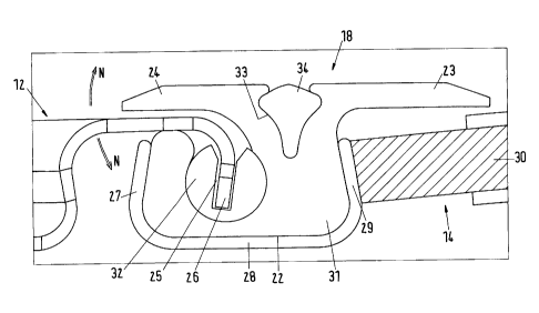
s
The assembly in fig. 1 is installed in the area of the crossover between two
coaches of a rail vehicle. It consists of a pivot plate 10, bridge plates 11,
12, 13
and floor plates 14, 20. The pivot plate 10, the bridge plate 11, 12, 13 and
the floor
plate 14 are connected to each other via connection elements 15, 16, 17, 18.
The
1.0 floor plate 14 is connected to a first coach body and the floor plate
20 is connected
to a second coach body. The pivot plate is rotatably mounted with its arc-
shaped
edge 19 on the floor plate 20. A tension bar 21, which covers the transition
between the pivot plate 10 and the floor plate 20 and is fixed to the floor
plate 20
by screws 42, is provided in the area of the transition between the pivot
plate 10
15 and the floor plate 20.
Fig. 2 is a sectional view along the line I-1 in Fig. 1 showing the floor
plate 12, a
connection element 18 according to the invention and the floor plate 14. The
connection element 18 has a profile shape with a base 22, a first lip 23, a
second
20 lip 24, and a groove-shaped recess 25 in the area of the base 22 of
the profile. A
bracket 26 of the bridge plate 12 pointing downward is inserted into the
groove-
shaped recess and glued therein. There is a little clearance between the
bracket
26 and the walls of the groove-shaped recess 25 for receiving glue. The lip 24
covers the edge area of the bridge plate 12 which is substantially formed by
the
25 bracket 26 bent downward. The gaps between the lip 23 and the floor plate
14,
respectively between the lip 23 and the bridge plate 12 shown in the figure
are not
mandatory. The lips can also rest directly on the plates. The same applies to
figure
3.
11
CA 02756378 2011-10-27
87541-4
The base 22 of the connection element 18 is inserted into a groove of the
floor
plate 14. The groove of the floor plate 14 is formed by the brackets 27, 28,
29
which surround the base 22 of the profile. In the shown embodiment, the bottom
of
the groove of the first floor element is wider than the aperture of the
groove, since
the brackets 27, 28, 29 are at an angle of less than 900 relative to each
other. The
basis 22 is thus tightly held in the groove. The bracket 29 is connected to
the
supporting element 30 of the floor plate 14. The lip 23 covers an edge area of
the
floor plate 14, in this case of the supporting element 30.
1.0 The connection element consists of a first elastic material 31
(respectively a part
made of a first elastic material 31) and a second material 32 (respectively a
part
made of a second material 32) with a higher rigidity. The part made of the
second
material 32 is a strand with an arc-shaped cross-section, in which the groove-
shaped recess 25 is embedded from above. In the embodiment shown here, the
first material 21 encompasses the second material 32, the aperture 40 of the
groove-shaped recess 25 being left open for receiving the bracket 26. Due to a
conical widening, the aperture 40 is wider than the width of the slit of the
subjacent
groove-shaped recess 25. The second material is located in an arc-shaped
recess
37 in the first material. In this embodiment, the part made of the second
material
32 is rotatably disposed in the part made of the first material 31. Due to
their
rotatability, the bridge plate 12 and the floor plate 14 which are connected
to each
other by the connection element 18 can easily move relative to each other in a
pitching motion. Alternately, the second material can also be fixedly attached
in the
first material.
The outer sides of the profile base 22, i.e. the sides which are encompassed
in the
brackets 27, 28, 29, are formed by the first material.
12
CA 02756378 2011-10-27
87541-4
A strand of a third material 34, having a wedge-shaped cross-section is
pressed
into a recess 33 between the first lip 23 and the second lip 24. The third
material
has a higher rigidity than the first material 31.
In order to undo the push-pull connection, the wedge-shaped strand made of the
third material 34 is first pulled out of the recess 33. The lip 24 is then
folded
upward which can be easily done via the recess 33. The bridge plate 12,
respectively its brackets are then pulled out of the connection element.
If the bracket 26 is glued to the part made of the second material 32, and the
part
32 is rotatably disposed in the part made of the first material 31 ¨ 31 and 32
thus
being not fixedly connected, the part 32 is pulled out of the connection
element 18
together with the bracket 26. The plates 12 and 14 are subsequently separated
and the plate 12 can be lifted upward.
If desired, the base 22 of the connection part 10 can be pulled out of the
groove
formed by the brackets 27, 28, 29, for instance by holding on to the lips 23,
24 and
pulling upward. This is however not necessary for disconnecting the connection
between the plates 12 and 14.
The assembly of the push and pull connection can occur in reverse order as
described above.
The part of the connection element 18 consisting of the first material 31 can
be
inserted into the groove of the first floor element 14, this part made of the
first
material 31 having the first lip 23, the second lip 24 and the base 22, the
base 22
being inserted into the groove of the first floor element 14. The bracket 26
of the
second floor element 12 pointing downward can then be inserted into the groove-
shaped recess 25 which is formed in the part of the connection element 18
consisting of the second material 32. The bracket is more specifically glued
into the
13
CA 02756378 2011-10-27
87541-4
groove-shaped recess 25. The part made of the second material 32 with the
bracket 26 of the second floor element 12 inserted therein, can finally be
inserted
into the part made of the first material 31, the first material 31
encompassing the
second material 32. The second material 32 preferably remains rotatable in the
first material 31. If possible and expedient, the afore-mentioned method steps
can
occur in different chronological orders. The result is the assembly shown in
fig. 2
Alternately, assembling the connection element 18 with the bridge plate 12 and
the
floor plate 14 can also occur in such a manner that the part consisting of the
first
lo material 31 is first inserted into the groove formed by the brackets 27,
28, 29 and
that the part consisting of the second material 32 is subsequently pressed
into the
first material, i.e. into the arc-shaped recess 37, to which end the lip 24 is
lifted as
much as required. The base 22 can thereby be widened depending on the
dimension of the recess, and fits tightly in the groove. The bracket 26 can
then be
inserted into the groove-shaped recess, to which end the lip 24 is lifted as
much as
required.
Another embodiment of a connection element is shown in fig. 3. Parts which are
the same in the first embodiment according to fig. 2 are labeled with the same
reference numbers. Unlike the embodiment according to fig. 2, the second
material
32 is not surrounded by the first material 31. The outer sides of the profile
base,
i.e. the sides which are encompassed in the brackets 27, 28, 29, are made of
the
first material 31 as well as the second material 32, which are connected to
each
other at a common edge 35 and together form the profile base 22. In this
embodiment both materials 31, 32 can for instance be co-extruded and the
profile
base is subsequently pressed into the groove formed by the brackets 27, 28,
29.
Another difference with respect to the embodiment according to Fig. 2, is that
the
groove-shaped recess 25 in the connection element 18 is widened downward in
direction of the end 36 of the bracket 26 and that the bracket 26 inserted
into the
14
CA 02756378 2011-10-27
87541-4
groove-shaped recess from above does not completely rest against the walls of
the
groove-shaped recess. The end 36 of the bracket 26 furthermore does not rest
on
the bottom of the groove. The bracket 26 and the bridge plate 12 connected to
it
can thus perform major pitching motions (angular motions relative to the
vertical)
relative to the floor plate 14. In this embodiment, the bracket 26 is not
fixed, more
specifically not glued in the groove-shaped recess. The angular motions of the
bridge plate 12 relative to the floor plate 14 are indicated by the arrows N.
The embodiments of a connection element shown are not limited to the
connection
element 18 shown in Fig. 1. The connection elements 15, 16 and 17 can also be
configured in this manner.