Note: Descriptions are shown in the official language in which they were submitted.
WO 2010/112950 PCT/IB2009/005137
ANNULAR LIGHT GUIDE ILLUMINATOR AND OPTICAL SCANNER
TECHNICAL FIELD
The present invention relates to the technical
field of optical devices for illuminating a zone to be
imaged, and corresponding imaging devices. Particularly, the
invention relates to imaging devices such as optical scanners
used for scanning a zone on an item in order to detect/read
some marking on said item.
BACKGROUND OF THE INVENTION
Imaging devices are of common use for scanning a
marking on an item, as illustrated, for example, with the
optical scanners disclosed in the US patents US 6,352,204 B2,
US 7,357,326 B2, US 7,370,801 B2 and US 7,419,098 B2. Such
marking may be a barcode (linear or 2-D like a datamatrix) or
any other pattern including identification data corresponding
to the item. In some cases, a marking on a surface of an item
is invisible or hardly visible to the unaided eye (a pattern
printed in phosphorescent, luminescent or fluorescent inks,
for example) and/or can be detected only under illumination
with specific light, in the UV or IR regions of the spectrum
for example. Moreover, even if the marking can be detected
with visible light, its size may be small or it may include
fine details of small scales so that said marking is
difficult to read, which makes good illumination conditions
necessary. Conventional light sources for scanners (depending
on which part of the spectrum is to be used for detection of
the marking) are incandescent lamps (typically for
wavelengths between about 400 nm to about 2500 nm), flash
lamps (like Xenon high-pressure flash lamp, for example),
WO 2010/112950 PCT/IB2009/005137
2
laser or Light-Emitting-Diodes (LEDs, emitting in the UV,
visible or IR regions, typically for wavelengths from about
250 nm to about 1 micron), Conventional photodetectors for
scanners are cameras of the CMOS or CCD type, photodiodes
(single or arrays), phototransistor or photoresistance
circuits, linear CMOS or CCD sensors.
A conventional optical scanner (which may be
hand-held or fixed) comprises a light source (which may
include filters) for illuminating a zone on an item with
appropriate light, an illuminator (which may include focusing
means) for delivering light received from said light source
appropriately to said zone, means for collecting light
reflected from said zone and transmitting it back to a
photodetector, a processing unit for analyzing a signal
delivered by the photodetector (and detecting/reading or
decoding data associated with a marking within said zone),
and a control unit for controlling the illumination source
and the processing unit.
Conventional hand-held scanners (either corded or
cordless) generally further include a power module for
supplying the scanner with power and may also comprise a
radio module for wireless communication (over Wi-Fi for
example), a display module (a liquid crystal display LCD, or
kinescope display, for example) for displaying measured data
or scanning parameters, and a controlling interface for
inputting scan conditions (including buttons having multiple
functions and an ON/OFF switch button). Conventional optical
scanners may further incorporate an RFID (Radio Frequency
Identification) circuit for reading RFID chips on a scanned
item (see, for example, US 6,264,106 B1), thus allowing the
scanner to read a combined optical/RFID marking.
A classical problem with an optical scanner is to
illuminate a zone, at a level of an item's reflective surface
WO 2010/112950 PCT/IB2009/005137
3
comprising a marking, homogeneously and with sufficient light
intensity, so that the detector of the scanner is capable to
read said marking from the reflected light, while minimizing
stray light and avoiding "hot spots" on the illuminated
surface which degrade the contrast and may cause severe image
processing problems; the detection of the marking may even
fail if the image sensor saturates. Moreover, the above
mentioned problem can, be enhanced in case of curved
reflective surfaces.
The above cited prior art documents have
considered this problem (see, for example, col.1, lines 36-51
of US 6,352,204 132; col.2, lines 16-19 of US 7,357,326 B2;
col. 2, lines 6-17 of US 7,370,801 B2 and col, 2, lines 1.11 of
US 7,419,098 B2) and proposed some specific illumination
techniques.
Document US 6,352,204 B2 discloses illuminating a
zone on an item at low incidence angle so as to minimize a
"wash out effect" caused by shiny or irregular surfaces.
However, there is a remaining problem with stray light.
Documents US 7,357,326 B2, US 7,370,801 B2 and US
7,419,098 B2 disclose using a illuminator having a nosepiece,
in the shape of a truncated pyramid, for directly
illuminating a zone on an item by placing the converging end
of said nosepiece near said zone so that light from the light
source reaches only the intended zone while being shielded
from much of the ambient light. The opposite diverging end of
the nosepiece receives light from the light source. However,
there are still some problems with direct reflection of light
.(back to the photodetector) on the internal face of the
nosepiece (even if this face may be an irregularly uneven
reflective one so as to scatter light) and also possible
"light spots" on the reflective surface of the item.
WO 2010/112950 PCT/IB2009/005137
4
SUMMARY OBr`THE INVENTION
The present invention is aimed at providing an
illumination technique that avoids the drawbacks of the prior
art.
The invention also relates to an optical scanner,
particularly a hand-held optical scanner, for detecting and
reading a marking at a surface of an item, which implements
such illumination technique.
According to one aspect of the invention, an
annular light guide illuminator is operable to guide light
received at an entry surface to an exit surface for
illuminating a zone at a distal end of said light guide
illuminator, and to allow for the transmission, through an
inner hole portion of said light guide illuminator, of light
reflected/emitted from said zone,
wherein:
said exit surface is a boundary surface portion of a
truncated-cone-shaped inner cavity of which base opens onto
said distal end, and of which truncated summit opposite to
said base opens onto said inner hole portion; and
said exit surface is operable to refract light received
from the entry surface to irradiate said zone with a
substantially uniform light intensity distribution.
With this annular structure of the illuminator,
light corning from the light source is guided within the
annular light guide, thus without travelling through the
inner hollow portion of the light guide, and the exit surface
of the light guide constitutes a boundary of an inner cavity
which is tapered from adjacent its base, to be placed near
the zone to be illuminated, toward its truncated summit
forming a bottleneck inner hole portion for transmitting back
WO 2010/112950 PCT/IB2009/005137
light reflected from the zone. This configuration has the
advantage to eliminate back transmission, through the inner
hole, of light originating directly from the exit surface,
Thus, stray light due to internal reflection can be
5 eliminated. Moreover, the distal end of the illuminator being
placed near, or in contact with, the target zone to be
irradiated, it constitutes a nosepiece which eliminates much
of stray light coming from external sources. Moreover, the
shape of the exit surface is chosen such that light refracted
toward the base of the inner cavity is uniform enough to
avoid forming light spots on the illuminated surface near, or
in near contact with, said base. All these features
contribute to improve the detection of a marking by a scanner
equipped with such illuminator, because the contrast of the
marking is strongly enhanced by homogeneous illumination.
The illuminator of the invention may as well
serve to transmit light emitted by a marking in the target
zone (for example, in response of an excitation light
transmitted through the exit surface, in case of a
fluorescent or phosphorescent marking) through its inner hole
portion,
Most useful shapes of portions of the exit
surface may be simply estimated from the law of refraction
(Snell's law) and the height and base area of the inner
cavity. However, a simple shape like the plane one ordinarily
suffices to provide good illumination conditions (for
example, in case of an inner cavity like a truncated pyramid,
for the portions of the surface of the inner cavity
corresponding to the faces of said truncated pyramid),
Another example of a simple shape providing good illumination
conditions is an exit surface like a conical frustum (which
corresponds to a straight generatrix), Better uniformity is
obtained with a shape of the exit surface corresponding to a
WO 2010/112950 PCT/IB2009/005137
6
convex curved generatrix (the concavity of the curve being
oriented toward the inner cavity). An even better uniformity
1s obtained if the generatrix is a parabola. Moreover, even
if the wide base end of the inner cavity opens onto the zone
to illuminate at the distal end of the light guide, the
external overall shape of the illuminator forming a nosepiece
may converge toward said distal end, thus concentrating
lighting on the target zone for enhancing the readability of
a marking within said zone.
The annular light guide illuminator according to
the invention may be designed to guide light corresponding to
an electromagnetic radiation comprised within the range from
optical UV to optical IR (i.e. about 400nm to about 2500 nm
wavelength). The materials constituting the light guide have
just to be selected according to the light to be guided, as
known to a skilled person. The illuminator may also be
designed for guiding electromagnetic waves of different
wavelengths,
Although the annular light guide of the invention
may be made hollow, i.e. with only inner and outer peripheral
material faces for guiding light by reflection and a material
exit face for irradiating the inner cavity by refracting some
of the guided light (and possibly, a material entry face), a
preferred embodiment of the invention corresponds to an
annular light guide illuminator being a solid body, made of a
substantially transparent material. Such material is selected
so as to be substantially transparent for the light to be
guided. The substantially transparent material of the solid
body may be chosen from the group consisting of the glasses,
the glass ceramic materials, the crystalline materials and
the plastic materials. The crystalline material is preferably
chosen from quartz, yttrium-aluminum garnet, and sapphire.
The optical plastic material is preferably chosen from
WO 2010/112950 PCT/IB2009/005137
polymethylpentene (TX), polymethyl methacrylate (PMMA),
methyl methacrylate styrene copolymer (NAS), styrene
acrylonitrile (SAN), polycarbonate (PC), and polystyrene
(PS),
For avoiding stray radiation (for example, for
protecting an operator from radiation), the annular light
guide illuminator according to the invention may further
comprise a shield made of a material which is opaque to the
guided light on a portion of the outer peripheral surface of
said light guide illuminator. In order to avoid stray light
originating from the inner peripheral surface of the inner
hole portion of the light guide, the illuminator according to
the invention may further comprise a shield made of a
material opaque to the guided light on a portion of an inner
peripheral surface of said light guide illuminator, in the
inner hole portion of the light guide illuminator. For
example, the above shield may be a cover or a coating.
The annular light guide illuminator according to
the invention may further comprise an RF antenna, mounted on
a portion of its peripheral boundary surface, adapted to
receive and transmit a RFID signal from/to an RFID chip at
the zone level. This embodiment of the illuminator according
to the invention, when used in a scanner, allows reading both
optical symbols and RF data present at a target zone,
The annular light guide illuminator according to
the invention is compatible with a conventional diffusive
insert for scattering light (arranged, for example, at a
level of the entry face). Nevertheless, in a preferred
embodiment, the annular light guide illuminator has a portion
of the exit surface, or of the entry surface, roughened so as
to scatter the light travelling toward the target zone. This
scattering enhances light uniformity at the target zone and
may be obtained by conventional techniques like surface
WO 2010/112950 PCT/IB2009/005137
a
sanding or by forming regular or irregular uneven
defects/patterns (serving as scattering centers) on the
surface. Thus, the illuminator according to the invention
does not depend on a diffusive insert between the light
source and the illuminator and may therefore be made more
compact.
The annular light guide illuminator according to
the invention may be further adapted to receive an optical
device to collect and transmit light reflected from the
irradiated zone and transmitted through the inner hole, For
example, the hollow portion of the annular light guide above
the inner cavity (i.e. between the entry part of the light
guide and the inner hole portion near the converging end of
the inner cavity) may be provided with means for mounting
such optical device. For example, these mounting means may
include any groove, notch, protrusion or thread on the inner
peripheral surface of the light guide (above the inner
cavity), or any other fastening means (using glue, screws or
inserted racks for example).
As explained above, the illuminator according to
the invention has many advantages. Moreover, as light is
guided within the annular guide, a great variety of overall
shapes are possible for the illuminator, and the illuminator
may thus be easily adapted to transfer radiation between
specific light source configurations and a target zone while
minimizing light losses and still having substantially
uniform lighting conditions within said zone. As a result, a
precise positioning of the illuminator's distal end onto the
target zone to be scanned is not required in order to have
substantially uniform illumination, Moreover, the shape of
the distal end of the illuminator may also be adapted for an
easier positioning in front of a target zone, as it is
particularly useful in case the illuminator is mounted on a
WO 2010/112950 PCT/IB2009/005137
9
hand-held scanner. For example, the distal end may be
slightly beveled without compromising uniformity of the
lighting on the target zone,
This annular configuration also allows using a
great variety of light sources, like incandescent lamps,
discharge tubes, flash lamps, laser or LEDs (from UV to IR),
or combinations of said light sources, for illuminating the
entry surface. As the entry surface may be adapted to the
light source, it is for example not necessary to use LEDs
equipped with lenses: ordinary LEDs having a wide emission
angle may be used instead. Also, filters may be easily
disposed at the entry face and/or the exit surface.
Also, the hollow inner part of the light guide
may be easily adapted for transmission of reflected light
toward a great variety of photodetectors like, for example,
those of a CMOS or CCD camera, photodiodes (single or
arrays), phototransistor or photoresistance circuits, or
linear CMOS or CCD sensors.
Another aspect of the invention relates to an
optical scanner comprising;
an annular light guide illuminator according to a
previous aspect of the invention, as mentioned above, adapted
to receive an optical device to collect and transmit light
reflected from the irradiated zone and transmitted through
the inner hole;
a light source operable to illuminate the entry surface
of said light guide illuminator; and
a photo-detector operable to receive light transmitted by
said optical device.
This optical scanner may comprise the above
mentioned annular light guide illuminator, including an
optional RF antenna, and may further include;
WO 2010/112950 PCT/IB2009/005137
a RF control circuit for sending an RFID signal to an
RFID chip at said zone level, through said RF antenna; and
a RFID reader operable to read an RFID signal received
from said RFID chip.
5 The above mentioned optical scanner according to
the invention may be a hand--held scanner including a power
module for powering the scanner, and may further comprise at
least one of wireless communication module, a display module
for displaying measured data or scanning parameters, and a
10 controlling interface for inputting scan conditions.
The present invention will be described more
fully hereinafter with reference to the accompanying drawings
in which like numerals represent like elements throughout the
different figures, and in which prominent aspects and
features of the invention are illustrated.
BRIEF DESCRIPTION OF THE DRAWINGS
Fig.1A-1C illustrate sectional views of annular
light guide illuminators according to the invention.
Fig.ID illustrates a partially cut-away
perspective view of the annular light guide illuminator of
Fig, 1A or 1B.
Fig,2A-2D illustrate some perspective views of
annular light guide illuminators of different shapes
according to the invention.
Fig,3A-3D illustrate views of annular light guide
illuminators with scattering faces according to the
invention.
WO 2010/112950 PCT/IB2009/005137
11
Fig.4A illustrates exploded perspective view of a
part of an illuminator according to an embodiment of the
invention, which includes an RFID antenna,
Fig. 4B illustrates a perspective view of the
illuminator shown in Fig,4A.
Fig.4C illustrates a sectional view of a
variation of the annular light guide illuminator shown in
Fig.4B.
Fig.5 illustrates a perspective view of a hand-
held scanner according to an embodiment of the invention.
Fig.6 illustrates an exploded perspective view of
a part of the hand-held scanner shown in Fig.-5,
Fig.7 illustrates a sectional view of a variation
of the annular light guide illuminator according to the
invention.
DETAILED DESCRIPTION
The principle of an illuminator according to the
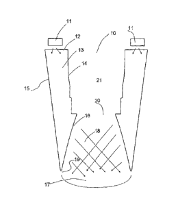
invention is illustrated in Fig. 1A showing a sectional view
of an annular light guide illuminator (10), with light
sources (11) illuminating an entry surface (12) of the light
guide (10). Light is guided within a guiding portion (13) of
the light guide (10), by reflection between an inner
peripheral surface (14) and an outer peripheral surface (15),
to an exit surface (16) which refracts light toward a target
zone (17) at a surface of an item (not represented). The exit
surface (16) constitutes a boundary surface, preferably of
convex curved shape, of an inner truncated-cone-shaped cavity
(18) with a diverging base end (19) which opens onto the
target zone (17) and a truncated summit (20) (i.e. a
converging end opposite to the base end) which opens onto an
inner hole portion (21) of the light guide.
WO 2010/112950 PCT/IB2009/005137
12
Fig. ID shows a partially cut--away perspective view of the
annular light guide illuminator (10), in case of a
transparent solid body guide (13).
Fig. 1B illustrates a cross-sectional view of an illuminator
(10) equipped with light sources (11) disposed all around the
entry surface (12) and a photodetector (30) for detecting
light retro-diffused (reflected) from the target zone (17) at
a surface (25) of an item, and transmitted through the inner
cavity (18) and inner hole portion. (21), In the illustrated
example, the photodetector (30) and the light sources (11)
are mounted on a same support (31) above the entry surface of
the illuminator. The inner peripheral boundary surface (14)
of the annular light guide (10) has protrusions for the easy
mounting of an optical device (32) within the inner hollow
portion (21), said optical device (32) serving in this case
for focusing light onto the photodetector (30).
Fig.1C illustrates a cross-sectional view of an illuminator
(10) equipped with a shield (40, 41) which, in this example,
is a hollow shield (or cover) made of opaque material
disposed around the inner and outer peripheral surfaces (14,
15) of the annular light guide. The outer portion (40) of the
shield covers the outer peripheral surfaces (15) and the
inner portion (41) of the shield covers the inner peripheral'
surface (14), and thus, there is no stray light from the
guiding portion (13) of the illuminator, neither toward the
exterior nor toward the inner hole portion of the light
guide, This configuration of the shield allows protecting the
eyes of an operator from light lost through the outer guiding
surface (15), as well as a photodetector (see Fig.1B) or
other optical device from stray light directly transmitted
through the inner guiding surface (14). The shield may as
well be a coating on the guiding surfaces of the light guide
WO 2010/112950 PCT/IB2009/005137
13
(for example, a layer of metal formed on these surfaces or an
opaque composition coating applied onto them).
The overall cross-section shape of the annular
light guide illuminator according to the invention is not
limited to that of truncated square pyramid (see E'ig,2D), but
may have any shape of which topology is annular. Also, the
shape of the inner hole portion may be arbitrary and only
must let reflected light coining from the target zone (or
light emitted by a target surface on an item) to be
transmitted to a photodetector. The annular shape may even be
bent at the level of the inner hole portion (21), if a mirror
is used to direct light received from the inner cavity (18)
toward the photodetector, for example. Some illustrative,
non-limitative, examples of shapes (overall shape, inner
cavity shape, inner hole shape) are given in Fig.2A-2C.
In an embodiment of the invention, the entry
surface (12) of the light guide is sanded to better diffuse
light (by light scattering due to the roughness of the
surface) within the guiding portion (13), as illustrated in
E'ig.3A. The exit surface may also be sanded to diffuse light
within the inner cavity (18). Scattering has a "smoothing"
effect and thus helps avoiding the formation of bright "hot"
spots on a target surface of an item. This is illustrated in
Fig.3B showing a cross-sectional view of an illuminator with
a sanded exit surface (15), Light scattering may also be
enhanced by means of ridges (regular or not) made on the exit
surface (for example), as illustrated in Fig.3C and 3D,
In the embodiment illustrated in Fig.3A-D, the
guiding portion (13) is a PNLYJA solid body for guiding UV
light of wavelength typically comprised between 300 nm to 450
nm.
In an embodiment of the invention, the
illuminator is adapted for further receiving an RFID antenna.
WO 2010/112950 PCT/IB2009/005137
14
This is illustrated in Fig.4A and 4B, wherein an antenna (43)
is wound around an outer peripheral surface of a cover (40)
disposed on the outer peripheral surface (15) of the annular
light guide (10), and connected to a RFID circuit (42).
However, the RFID antenna may be disposed in other parts of
the illuminator, As an example, Fig.4C shows a RFID antenna
(43) wound within the inner hole portion (21) of the annular
light guide, around an optical device (32) for focusing light
received through the truncated summit (20) of the inner
cavity (18) onto the photodetector (30) mounted on the
support (31). Also shown in Fig,4D, a light source (11) which
is a bar of LEDs (33) mounted on the support (31) to directly
facing the entry surface (12) of the annular light guide. The
RFID antenna may also have another shape (not necessarily a
wound wire, depending on the RF signals to be
delivered/received), as known in the art,
Fig.5 illustrates a perspective view of a hand-
held optical scanner (50) according to the invention, This
scanner includes the annular light guide illuminator (10) for
illuminating a portion of a surface (25) of an item (here, a
can), a housing with a handle (51) easy to grasp for an
operator, a power module (52) for powering the scanner, and a
display (53) (LCD) with a touchpad screen to avoid buttons (a
keyboard being displayed on the LCD), except for a
ON/OFF/Reset button (not shown), Fig.6 is an exploded view of
the part of the hand-held scanner (50) including the
illuminator (10) with a cover (40) and an optical device (32)
mounted on a support (31) together with light sources (11)
(the photodetector is not shown). The cordless optical
scanner (50) is balanced for easier handling and includes the
following components:
-- an optical bloc including, a light source (11) (with LEDs),
the annular light guide illuminator (10), with the cover
WO 2010/112950 PCT/IB2009/005137
(40), for illuminating a barcode or a datamatrix on the item
(25), and a CCD camera (32), mounted on the support (31);
-- the LCD color touch screen (53);
a main board (not represented) hosting a CPU unit for
5 reading/decoding barcodes or matrix codes, and controlling
the scanner;
- a wireless communication board (GSM/GPRS);
- the pack of batteries (52); and
- the ergonomic housing (plastic),
10 Several variations of the above hand-held scanner
have been realized; it may either be autonomous concerning
the processing operations of reading/identifying or
authenticating a marking or connected to a station having
said processing capabilities (in case identification or
15 authentication of the item is carried out by comparison with
data in an external database, for example), the connection
with the station may be by wire (for example, via Ethernet or
phone modem) or wireless (for example, via either of Goa-Fi.
GSM/GPRS or Bluetooth). Even in case of autonomous processing
capabilities, the hand-held scanner may still include
communication capabilities. The hand-held scanner may also be
provided with connection means for charging a battery of its
power module (for example, to be connected to a docking
station). In a preferred embodiment, the hand-held scanner is
balanced and the end of its nosepiece may further be beveled
so that an operator may easily scan an item in any position
(standing, squatting or kneeling, for example).
The invention is not limited to the above
embodiments and various modifications may be made without
departing from the scope of the invention as defined by the
claims. For example, the shape of the illuminator may be
varied (as illustrated, for example, in Fig..7, with side
WO 2010/112950 PCT/IB2009/005137
16
entry surface (12)). Also, the above mentioned (hand-held)
scanner may include the illuminator according to any of its
variations and/or may be adapted for using other parts of the
spectrum, still within the UV-IR range, for illuminating the
target zone or detecting light reflected/emitted from this
very zone.