Note: Descriptions are shown in the official language in which they were submitted.
VIBRATING SCREEN SUSPENSION SYSTEMS
BACKGROUND OF THE INVENTION
This invention relates to vibrating screens and more particularly to
suspension and
damping systems for vibrating screens.
The aggregate industry utilizes many styles of screen machines to sort
aggregates
by size. Most screen machines utilize vibration to agitate the mixture of
aggregates to
promote separation through various sized openings in the screening surfaces.
Sorting is
achieved by undersized particles passing through the openings in the screening
surface
and the oversize particles being retained above the screen surface. These
machines
usually have some type of vibrating mechanism to shake the unit and its
screening
1
CA 2756965 2018-01-15
surfaces. The vibrating mechanisms usually include an unbalanced weight
mounted on
one or several rotating shafts which when rotated, force a cycling motion into
the screen
machine. The resulting motion can have a circular path, linear path,
elliptical path, or
any combination of those shapes. This cycling motion is referred to as the
screen stroke
and can range in total displacement in any direction from less than 1/4" to
more than 1".
These screen machines are normally supported on springs which isolate the
vibrating machine from the mounting structure.
Fixed inclined screens are constructed so the screen surfaces are sloped,
usually
toward the discharge end, to aid material movement to the end and off the
screen. These
vibrating screens are usually supported with four springs or spring groups,
one each at the
corners of the screen. The springs are usually mounted in a vertical
orientation.
Sometimes a screen is designed to be operated in various sloped positions.
This is
frequently found in portable equipment that requires a lower profile for
travel as well as
multiple sloped positions as needed for various screening applications.
Now referring to Fig. 1, in the case of a screen that must operate at various
sloped
positions, vertically mounted springs 14 and 16 would become tilted with the
change of
slope and become unstable. Therefore, the springs in this case are typically
oriented so
they are tilted towards each other within the spring grouping 10 to provide
spring stability
as the support frame 12 changes slope. These are also commonly found in two
spring
groups, or in an alternate arrangement with a center vertical spring.
2
CA 2756965 2018-01-15
The overall spring rate, or stiffness, of the spring groups are affected as
the
support frame changes slope. All the spring groups change together as the
slope
changes. If the center of gravity of the screen is above a plane that goes
through the
spring attachment points, there will be a shift of weight to the discharge end
of the screen
as the slope increases. It would be desired to have the spring groups on that
end to
increase stiffness to help support the weight shift. Even if the center of
gravity is on the
plane through the spring attachments, the heavy load of unsorted material on
the upper
levels will raise the mass center of the screen which will shift more weight
to the
discharge spring groups as the slope increases.
In order to provide significant isolation from the mounting structure, the
spring
suspension has a sufficiently low spring rate to minimize vibration
transmittance into the
mounting structure. The natural frequency of the spring supported machine is
lower than
the vibration frequency in order to provide isolation. Since the spring
natural frequency
is lower than the operating frequency, the machine must pass through the
natural
frequency speed range during start up and shut down. When the machine passes
through
the suspensions natural frequency range, that motion becomes amplified and the
movement of the screen body becomes much larger than the motion (stroke)
during
normal operation. This large motion or surge causes higher forces and stresses
to the
screen and support structure which can cause damage to both.
3
CA 2756965 2018-01-15
It is desired to employ a mechanism to dampen the surge during that start up
and
shut down sequence. There are various styles of damping methods used today,
most
utilizing some type of friction device to dissipate some of the energy during
the surge.
Most devices used today either require continual maintenance or dampens only
vertical
motion. There are mechanisms in the industry today that utilize a yoke type
containment
device and a single pivot link. These only contact the screen body stub post
when
moving vertically, not horizontally.
Since it is an elongated yoke, it makes point contact on a horizontal surface
rather
than the rounded surfaces of the containment cup. The yoke style also does not
provide
horizontal containment. See Fig. 2.
Consequently, there is a need for improvement in suspension and damping
systems for vibrating screens.
SUMMARY OF THE INVENTION
More specifically, an object of the invention is to provide a cost effective
vibrating
screen.
It is a feature of the present invention to include inwardly angled non-
vertically
oriented internally parallel spring groups.
4
CA 2756965 2018-01-15
It is an advantage of the present invention to reduce the space requirements
for
attachment of the spring groups to the base frame, thereby increasing design
options
which meet the compactness requirements for highway transportation.
It is another object of the present invention to decrease problems which arc
associated with excess vibration of the screen when the operating frequency
equals or is
lower than the natural frequency of the springs.
It is another feature of the present invention to only include a bi-
directional dual
pivot friction damping control system.
It is another advantage of the present invention to provide a reduction in
problems
associated with operating the screen at a frequency below the natural
frequency of the
springs.
The present invention includes the above-described features and achieves the
aforementioned objects.
CA 2756965 2018-01-15
In a broad aspect, the invention pertains to a vibrating screen comprising a
support
structure which is configured to be transported on a highway and is configured
to be
transported on a highway and is configured to be adjusted to variable angles.
A vibrating
screen is configured for sorting aggregate by size, a discharge conveyor is
configured for
creating a pile of sorted aggregate, and there are a pair of internally
parallel spring groups.
The pair of internally parallel spring groups are arranged in an angled
orientation toward a
central location so as to oppose the other, each of the pair being coupled to
both the support
structure and the vibrating screen.
In a further aspect, the invention provides a vibrating screen comprising a
support
structure which is configured to be hydraulically adjusted to variables
angles. A multi-deck
vibrating screen is configured for sorting aggregate by size, and a plurality
of discharge
conveyors are configured for creating separate piles of sorted aggregate. A
plurality of
springs are arranged in groups, each of the plurality of springs being
arranged as to oppose
another of the plurality of springs. Each of the plurality of springs is
coupled to both the
support structure and the vibrating screen. A dual pivot damping system is
configured for
damping vibration in two orthogonal axes comprising a screen connection, on
the vibrating
screen, a base connection on the support structure, and a plurality of
pivoting leg members
coupled in series between the screen connection and the base connection.
6
CA 2756965 2018-01-15
In a still further aspect, the invention embodies a vibrating screen
comprising a
support structure which is configured to be hydraulically adjusted to variable
angles, and a
multi-deck vibrating screen configured for sorting aggregate by size. A
plurality of
discharge conveyors are configured for creating separate piles of sorted
aggregate, and a
plurality of springs are arranged in groups, each of the plurality of springs
being arranged as
to oppose another of the plurality of springs. Each of the plurality of
springs is coupled to
both the support structure and the vibrating screen. A dual pivot damping
system is
configured for damping vibration in two orthogonal axes comprising a screen
connection, on
the vibrating screen, and a base connection on the support structure. A
plurality of pivoting
leg members are coupled in series between the screen connection and the base
connection.
The plurality of pivoting leg members are disposed adjacent to a readily
replaceable friction
plate. There is a containment cup coupled to the plurality of pivoting leg
members, and
there is a stub post coupled to the screen and disposed in part within the
containment cup. A
resilient member is disposed within the containment cup for cushioning, and
reducing wear
on the containment cup and the stub post. The resilient member is a rubber
like sleeve that
is resilient to permanent deformation and returns to original shape after
contact with the stub
post and the containment cup.
Accordingly, the present invention comprises a vibrating screen suspension and
damping system which includes inwardly inclined internally parallel spring
pairs and/or a
dual pivot bi-directional damping mechanism.
6a
CA 2756965 2018-01-15
CA 02756965 2011-11-07
BRIEF DESCRIPTION OF THE DRAWINGS
In the following description of the drawings, in which like reference numerals
are
employed to indicate like parts in the various views:
FIG. 1 is a perspective view of the of a internally inwardly angled spring
group of
the prior art.
FIG. 2 is a perspective view of a pair of single pivot uni-directional
friction
damping structures of the prior art.
FIG. 3 shows a side view a vibrating screen of the present invention deployed
in a
horizontal position.
FIG. 4 shows a side view a vibrating screen of Fig. 3 deployed in an inclined
position.
FIG. 5 shows a side view of a vibrating screen of Figs. 3 and 4 with dual
pivot
damper of the present invention.
FIG. 6 shows a typical vibrating screen in combination with a dual pivot
damper
of the present invention, in a typical at rest orientation.
FIG. 7 shows a typical vibrating screen in combination with a dual pivot
damper
of the present invention, in an orientation which is displaced from an at rest
orientation.
7
CA 02756965 2011-11-07
FIG. 8 shows a more detailed view of the damper mechanism of Figs. 5-7.
FIG. 9 shows a simplified view of a vibrating screen of the present invention
with
enlarged details of the dual pivot damper mechanism of the present invention.
DETAILED DESCRIPTION OF THE DRAWINGS
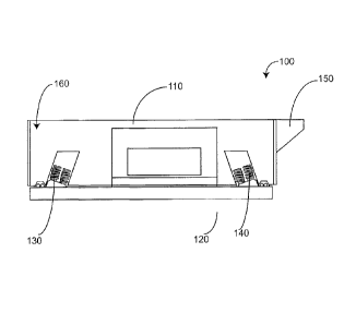
Referring now to the drawings, where like numerals refer to like matter
throughout, and more particularly to Fig. 3, there is shown a system of the
present
invention which includes a vibrating screen box 110 which is supported by
discharge
spring group 130 & feed end spring group 140 on the support frame 120. In this
example, the feed end spring group 140 is tilted so the top of the springs
angle toward the
discharge end. The discharge spring group 130 is tilted toward the feed end.
The
opposed spring groups push the screen box between the two groups to provide
stability
when the screen base slope changes. These spring groups are mirrored on the
opposite
side of the screen and are coupled to the support frame 120 so as to allow the
vibrating
screen box 110 to vibrate, yet isolate the support frame from much of the
vibration.
Now referring to Fig. 4 there is shown an example where the support frame 120
is
repositioned to a desired sloped position. The discharge spring group 130 now
has the
8
CA 02756965 2011-11-07
center axis of the springs positioned closer to vertical which increases their
effective
vertical spring stiffness.
The springs can be designed so that the natural frequency of the screen on the
springs is such that it can amplify the stroke of the screen, making it more
active. The
amplification effect is related to how close the natural frequency is to the
operational
speed. The closer the suspension natural frequency is to the operational
speed, the more
amplification there will be. The stiffer the springs, the higher the
suspension's natural
frequency.
If more action is desired on the discharge end as weight is shifted toward
that end
as slope increases, those springs stiffness and orientation can be established
so that as the
slope increases, the increased spring stiffness will produce more motion
amplification on
the discharge end of the screen.
Now referring to Fig. 5 there is shown a vibrating screen of Figs. 3 and 4
together
with the dual pivot damper of the present invention. More particularly there
is shown:
a side view of the vibrating screen supported on springs groups 130 and 140 on
a
support structure. The opposing dual pivot vibration damper mechanisms 41 are
located
on opposite ends. The screen motion is planer to this view. There are mirror
images of
these vibration dampers on the opposite side, in a parallel plane,
symmetrically
positioned about a central plane.
9
CA 02756965 2011-11-07
Now referring to Fig. 6 there is shown a more typical horizontal vibrating
screen
together with the dual pivot damper of the present invention, including a side
view of a
horizontal type screen 31 supported on springs 21, on a support structure 11.
The
opposing dual pivot vibration damper mechanisms 41 are located on opposite
ends.
Now referring to Fig. 7 there is shown a screen displaced to the right, the
left
damper has the link nearly aligned which provides a "hard" link to prevent
further
movement, preventing the unit from falling off the springs.
Now referring to Fig. 8 there is shown a more detailed view of the dual pivot
damper 41 of Figs. 5-7 including:
A vibrating screen body 31; some clearance 802 inside the containment cup 804
(outer face removed to show internal clearance) and its resilientiner 803,
such as UHMW
polyethylene or nylon to the stub post 805 attached to stub post mounting
plate 806
which is attached to screen body 31; upper pivot link 807 attached to
containment cup
804 and pivot hinge 808 and lower link 809 which is attached to base pivot 810
and there
to pivot base 811. Note, resilient liner could be substituted with a covering
or sleeve over
the stub post 805.
The clearance 802 may be larger than the stroke of the screen body. If the
screen
body is designed to move on a linear stroke of 3/4 total movement that is +/-
3/8" the
clearance would be slightly larger than 3/8" so that the high frequency motion
of the
screen body is not influenced by the damper. The damper will be pushed to a
neutral
CA 02756965 2011-11-07
position by the action of the screen body where it will remain due to the
friction of the
joints. This makes the damper position self adjusting, self neutralizing,
under varying
loads. Self adjusting is important since heavier loads in the screen body will
compress the
support springs more, lowering the position of the screen body during
operation.
Now referring to Fig. 9, which shows an end view of the screen 31 and the
mirrored vibration dampers on opposing sides. Motion is perpendicular to the
image.
The support structure line is shown on multiple levels to allow showing the
damper pivot
arms straightened out for clarity. The damper on the RH side is slightly
different
showing a dual lower link configuration, while the LH side shows a single
lower link
with friction plates on both sides of the pivot hinges. These would be the
same in
practice and only shown this way to show different possible arrangements.
More specifically there is shown: a support structure 11 line (shown at
multiple
levels for clarity) but a single level support is preferred. Also shown is a
pivot base
(rigidly attached to support structure 811; a lower pivot link 809 tying upper
pivot link
807 to pivot base 811; outer pivot plates with a hinge bolt 905 theretlu-ough.
Also shown are screen springs 21 supporting spring box 31 above support
structure 11 and a hinge bolt nut 907 to preload compression spring 908, which
is used to
maintain pressure on friction plates 909. Also shown is upper pivot link 807
tying
containment cup (shown with outer cover plate); to lower pivot link 809 with
clearance
802 between containment cup sleeve or rubber like liner 803 and screen stub
post 805
11
CA 02756965 2011-11-07
which is rigidly attached to stub post mounting plate 806 which is rigidly
attached to
screen body 31.
It is believed that when these teachings are combined with the known prior art
by
a person skilled in the art of boom truck design and equipment manufacture,
many of the
beneficial aspects and the precise approaches to achieve those benefits will
become
apparent.
It will be understood that certain features and sub-combinations are of
utility and
may be employed without reference to other features and sub-combinations. This
is
contemplated by and is within the scope of the claims.
Since many possible embodiments may be made of the invention without
departing from the scope thereof, it is understood that all matter herein set
forth or shown
in the accompanying drawings is to be interpreted as illustrative and not in a
limiting
sense.
12