Language selection

Search

Patent 2757111 Summary

Third-party information liability

Some of the information on this Web page has been provided by external sources. The Government of Canada is not responsible for the accuracy, reliability or currency of the information supplied by external sources. Users wishing to rely upon this information should consult directly with the source of the information. Content provided by external sources is not subject to official languages, privacy and accessibility requirements.

Claims and Abstract availability

Any discrepancies in the text and image of the Claims and Abstract are due to differing posting times. Text of the Claims and Abstract are posted:

  • At the time the application is open to public inspection;
  • At the time of issue of the patent (grant).
(12) Patent Application: (11) CA 2757111
(54) English Title: EXPLOSIVE CHARGE
(54) French Title: CHARGE EXPLOSIVE
Status: Deemed Abandoned and Beyond the Period of Reinstatement - Pending Response to Notice of Disregarded Communication
Bibliographic Data
(51) International Patent Classification (IPC):
  • F42B 3/02 (2006.01)
  • F41H 11/11 (2006.01)
  • F41H 11/14 (2006.01)
(72) Inventors :
  • YOUNG, COLIN DOUGLAS (United Kingdom)
(73) Owners :
  • CHEMRING ENERGETICS UK LIMITED
(71) Applicants :
  • CHEMRING ENERGETICS UK LIMITED (United Kingdom)
(74) Agent: MBM INTELLECTUAL PROPERTY AGENCY
(74) Associate agent:
(45) Issued:
(86) PCT Filing Date: 2010-03-26
(87) Open to Public Inspection: 2010-10-07
Availability of licence: N/A
Dedicated to the Public: N/A
(25) Language of filing: English

Patent Cooperation Treaty (PCT): Yes
(86) PCT Filing Number: PCT/GB2010/050514
(87) International Publication Number: WO 2010112900
(85) National Entry: 2011-09-29

(30) Application Priority Data:
Application No. Country/Territory Date
0905688.8 (United Kingdom) 2009-04-01

Abstracts

English Abstract


An explosive charge (1) comprising an elongate casing (2) with elongate
grooves (3,4) miming along the casing,
each groove locally reducing the thickness of the casing. The grooves are
distributed in two or more groups around the circumference
of the casing and the edge-to-edge spacing between each adjacent pair of
grooves in a group is less than the edge-to-edge
spacing between each pair of adjacent groups. Detonation causes the casing to
break at a pair of grooves in one of the groups and
form a fragment from material between the pair of grooves, the fragment
cutting an obstacle (28).


French Abstract

L'invention concerne une charge explosive (1) comprenant une douille allongée (2) présentant sur sa longueur des rainures allongées (3, 4), chaque rainure réduisant localement l'épaisseur de la douille. Les rainures sont réparties en deux groupes ou plus autour de la circonférence de la douille, et l'espacement bord à bord entre chaque paire adjacente de rainures dans un groupe est inférieur à l'espacement bord à bord entre chaque paire de groupes adjacents. La détonation entraîne la rupture de la douille au niveau d'une paire de rainures dans l'un des groupes et forme un fragment de matière entre la paire de rainures, le fragment coupant un obstacle (28).

Claims

Note: Claims are shown in the official language in which they were submitted.

5
Claims
1. An explosive charge comprising an elongate casing with elongate grooves
running along the casing, each groove locally reducing the thickness of the
casing, wherein the grooves are distributed in two or more groups around the
circumference of the casing and the edge-to-edge spacing between each
adjacent pair of grooves in a group is less than the edge-to-edge spacing
between each pair of adjacent groups.
2. The charge of claim 1 wherein each group of grooves has no more than two
grooves.
3. The charge of any preceding claim wherein there are no more than four
groups
of grooves distributed around the circumference of the casing.
4. The charge of claim 2 and claim 3 wherein there are no more than four pairs
of
grooves distributed around the circumference of the casing.
5. The charge of any preceding claim wherein the grooves are distributed in
three
or more groups around the circumference of the casing
6. The charge of any preceding claim wherein the edge-to-edge spacing between
each groove in a group is greater than zero, so that each groove has an edge
which is separated from an adjacent edge of an adjacent groove by a non-
grooved portion of the casing.
7. The charge of claim 6 wherein the average angle subtended by the non-
grooved portions at the centre of the casing, when viewed in transverse cross-
section, is less than 5°.
8. The charge of any preceding claim wherein the average edge-to-edge spacing
between the adjacent edges of each groove within a group is less than the
average edge-to-edge spacing between the adjacent edges of adjacent groups
by a factor of 10 or more.

6
9. The charge of any preceding claim wherein the grooves taper outwardly when
viewed in transverse cross-section.
10. The charge of any preceding claim wherein the average angle subtended by
each groove at the centre of the casing, when viewed in transverse cross-
section, is less than 10°.
11. The charge of any preceding claim wherein the total angle subtended by the
grooves at the centre of the casing, when viewed in transverse cross-section,
is
less than 90°, preferably less than 60°, and most preferably
less than 30°.
12. The charge of any preceding claim wherein the casing has an internal wall
and
an external wall; and wherein the grooves are formed in the external wall.
13. The charge of claim 12 wherein the internal wall is substantially circular
in
cross-section.
14. The charge of any preceding claim wherein the casing has a threaded head
end
adapted to be coupled to the tail end of an adjacent charge, and a threaded
tail
end adapted to be coupled to the head end of an adjacent charge.
15. A kit of parts comprising two or more charges according to any preceding
claim, each charge having a head end adapted to be coupled to the tail end of
an adjacent charge, and a tail end adapted to be coupled to the head end of an
adjacent charge.
16. A method of cutting an obstacle using the explosive charge of any
preceding
claim, the method comprising detonating explosive material in a compartment
of the casing, the detonation causing the casing to break at a pair of grooves
in
one of the groups and form a fragment from material between the pair of
grooves, the fragment cutting the obstacle.
17. The method of claim 16 further comprising coupling two or more of the
charges head to tail; and detonating explosive material in each charge.

Description

Note: Descriptions are shown in the official language in which they were submitted.


CA 02757111 2011-0&29
WO 2010/112900 PCT/GB2010/050514
1
EXPLOSIVE CHARGE
FIELD OF THE INVENTION
The present invention relates to an explosive charge, particularly a charge
suitable for
use in a so-called "Bangalore Torpedo".
BACKGROUND OF THE INVENTION
A conventional explosive charge is described in W02007/099362. The charge has
one or more longitudinal concave grooves. Upon explosion, the contour of the
groove
results in a focussing effect on the wall material. The groove does not reduce
the local
thickness of the wall of the charge.
Another conventional explosive charge is described in GB-A-2214618. The inner
face of the lining is formed with a set of V-shaped grooves interlinked around
the axis
of the charge. The grooves reduce the local thickness of the lining and result
in
material being ejected in a plurality of shaped charge jets one from each
outward
facing V-shaped region of the lining.
SUMMARY OF THE INVENTION
A first aspect of the invention provides an explosive charge comprising an
elongate
casing with elongate grooves running along the casing, each groove locally
reducing
the thickness of the casing, wherein the grooves are distributed in two or
more groups
around the circumference of the casing and the edge-to-edge spacing between
each
adjacent pair of grooves in a group is less than the edge-to-edge spacing
between each
pair of adjacent groups.
A second aspect of the invention provides a kit of parts comprising two or
more
charges according to the first aspect of the invention, each charge having a
head end
adapted to be coupled to the tail end of an adjacent charge, and a tail end
adapted to be
coupled to the head end of an adjacent charge.
A third aspect of the invention provides a method of cutting an obstacle using
the
explosive charge of the first aspect of the invention, the method comprising
detonating

CA 02757111 2011-0&29
WO 2010/112900 PCT/GB2010/050514
2
explosive material in a compartment of the casing, the detonation causing the
casing
to break at a pair of grooves in one of the groups and form a fragment from
material
between the pair of grooves, the fragment cutting the obstacle.
In GB-A-2214618 the grooves are distributed uniformly around the circumference
of
the lining. In contrast, according to the present invention the grooves are
distributed
non-uniformly around the circumference of the casing so that they are bunched
together in two or more groups. The relatively small edge-to-edge spacing
between
each adjacent pair of grooves in a group results in the generation of high
energy
fragments which can cut efficiently through an obstacle.
The edge-to-edge spacing between each groove in a group may be zero, but
preferably
it is greater than zero so that each groove has an edge which is separated
from an
adjacent edge of an adjacent groove by a non-grooved portion of the casing.
Various other preferred features of the invention are set out in the dependent
claims.
BRIEF DESCRIPTION OF THE DRAWINGS
Embodiments of the invention will now be described with reference to the
accompanying drawings, in which:
Figure 1 is a plan view of an explosive charge;
Figure 2 is a longitudinal sectional view taken along a line B-B in Figure 1;
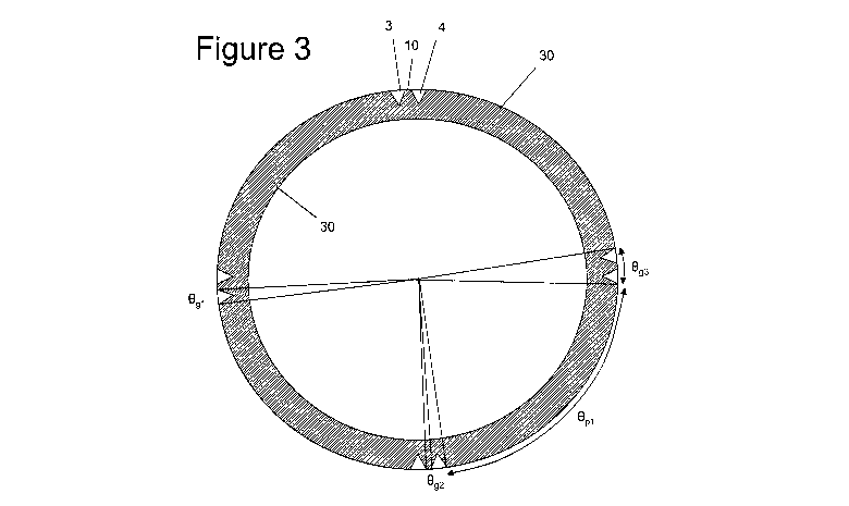
Figure 3 is a transverse sectional view taken along a line A-A in Figure 1;
Figure 4 is a close up transverse sectional view showing a pair of grooves;
Figure 5 is a perspective view showing a set of charges in use as a Bangalore
torpedo;
and
Figure 6 is a schematic sectional view showing the torpedo exploding.
DETAILED DESCRIPTION OF EMBODIMENT(S)

CA 02757111 2011-0&29
WO 2010/112900 PCT/GB2010/050514
3
An explosive charge 1 shown in Figure 1 comprises an elongate casing 2 with
grooves
3, 4 running along the external wall of the casing. Figure 3 is a transverse
sectional
view taken along a line A-A in Figure 1, which shows that there are four pairs
of
grooves distributed around the circumference of the casing. The grooves are
all
identical so only the pair 3, 4 will be described in detail with reference to
Figure 4.
Each groove is V-shaped with a depth d. Each groove locally reduces the
thickness of
the casing, so the thickness tl of the casing at the bottom of each groove is
less than
the thickness t2 in the un-grooved portion between adjacent pairs of grooves.
The grooves 3, 4 are separated from each other by a small non-grooved portion
10 of
the casing in which the thickness of the casing is substantially constant. The
grooves
3, 4 are relatively narrow, as is the width of the non-grooved portion 10
which
separates the groove 3 from the groove 4. Specifically, each groove subtends
an angle
Ogl of only about 4 and the edge-to-edge angular spacing Ogg between the
edges of
adjacent grooves within a pair is only about 2 . Therefore each pair subtends
an angle
Og3 between its two outer edges of about 10 , and the edge-to-edge angular
spacing Opl
(shown in Figure 3) between the edges of adjacent pairs of grooves is about 80
.
The internal wall of the casing is circular in cross-section for ease of
manufacture and
to maximise the space available for explosive material.
Referring to Figure 2, which is a longitudinal sectional view taken along the
line B-B
shown in Figure 1, the casing has an internally threaded head end 11 adapted
to be
screwed to the tail end of an adjacent charge, and an externally threaded tail
end 12
adapted to be screwed to the head end of an adjacent charge.
Figure 5 shows the device in use as a Bangalore torpedo being prepared to
clear a path
through a series of wires 20 (for instance barbed wire or razor wire). A
number of
casing units 21, 22 (in this case two, but optionally more than two) are
screwed
together head to tail. An explosive charge (not shown) is contained inside the
torpedo
along its full length. A nose cone 23 is screwed to the head end of the front
casing
unit, and a detonator housing 24 with an initiator is screwed to the tail end
of the rear
casing. The torpedo is fed under the barbed wire and placed on the ground with
two
pairs of grooves facing up and oriented at approximately +/- 45 to the
vertical.

CA 02757111 2011-0&29
WO 2010/112900 PCT/GB2010/050514
4
The charge is then detonated, causing the casing to break initially at the
bases of the
eight grooves where the thickness tl is at a minimum. The casing material
between
the grooves forms four small pre-defined fragments which are ejected at
approximately +/- 45 to the vertical. The fragments from the two downwardly
pointed pairs of grooves impact the ground and are not shown in Figure 6.
However
the fragments 25, 26 from the two upwardly pointed pairs of grooves are
ejected
upwardly and cut the barbed wire at locations 27 and 28 respectively, clearing
a path
through the obstacle. The relatively large volume of casing between the pairs
of
grooves generates a set of relatively small and low energy particles 29, 30,
31 which
have less cutting effect than the fragments 25, 26. Spacing the pairs of
grooves apart,
and making the spacing between adjacent grooves in a pair relatively small,
ensures
that the fragments 25, 26 have relatively high energy and cutting
effectiveness. It is
also believed that the tapering profile of the grooves (in this case a V-
shaped profile)
provides a focusing effect on the detonation wave.
Note that Figure 6 does not show the true shape of the fragments 25, 26 or
lower
energy particles 29-31 but merely intends to show the mode of operation
schematically.
Although the invention has been described above with reference to one or more
preferred embodiments, it will be appreciated that various changes or
modifications
may be made without departing from the scope of the invention as defined in
the
appended claims.

Representative Drawing
A single figure which represents the drawing illustrating the invention.
Administrative Status

2024-08-01:As part of the Next Generation Patents (NGP) transition, the Canadian Patents Database (CPD) now contains a more detailed Event History, which replicates the Event Log of our new back-office solution.

Please note that "Inactive:" events refers to events no longer in use in our new back-office solution.

For a clearer understanding of the status of the application/patent presented on this page, the site Disclaimer , as well as the definitions for Patent , Event History , Maintenance Fee  and Payment History  should be consulted.

Event History

Description Date
Time Limit for Reversal Expired 2015-03-26
Application Not Reinstated by Deadline 2015-03-26
Deemed Abandoned - Failure to Respond to Maintenance Fee Notice 2014-03-26
Inactive: Reply to s.37 Rules - PCT 2012-01-06
Inactive: Cover page published 2011-11-29
Inactive: IPC assigned 2011-11-17
Inactive: Request under s.37 Rules - PCT 2011-11-17
Inactive: Notice - National entry - No RFE 2011-11-17
Application Received - PCT 2011-11-17
Inactive: First IPC assigned 2011-11-17
Inactive: IPC assigned 2011-11-17
National Entry Requirements Determined Compliant 2011-09-29
Application Published (Open to Public Inspection) 2010-10-07

Abandonment History

Abandonment Date Reason Reinstatement Date
2014-03-26

Maintenance Fee

The last payment was received on 2013-03-13

Note : If the full payment has not been received on or before the date indicated, a further fee may be required which may be one of the following

  • the reinstatement fee;
  • the late payment fee; or
  • additional fee to reverse deemed expiry.

Please refer to the CIPO Patent Fees web page to see all current fee amounts.

Fee History

Fee Type Anniversary Year Due Date Paid Date
Basic national fee - standard 2011-09-29
MF (application, 2nd anniv.) - standard 02 2012-03-26 2011-09-29
MF (application, 3rd anniv.) - standard 03 2013-03-26 2013-03-13
Owners on Record

Note: Records showing the ownership history in alphabetical order.

Current Owners on Record
CHEMRING ENERGETICS UK LIMITED
Past Owners on Record
COLIN DOUGLAS YOUNG
Past Owners that do not appear in the "Owners on Record" listing will appear in other documentation within the application.
Documents

To view selected files, please enter reCAPTCHA code :


To view images, click a link in the Document Description column. To download the documents, select one or more checkboxes in the first column and then click the "Download Selected in PDF format (Zip Archive)" or the "Download Selected as Single PDF" button.

List of published and non-published patent-specific documents on the CPD .

If you have any difficulty accessing content, you can call the Client Service Centre at 1-866-997-1936 or send them an e-mail at CIPO Client Service Centre.


Document
Description 
Date
(yyyy-mm-dd) 
Number of pages   Size of Image (KB) 
Representative drawing 2011-09-29 1 57
Drawings 2011-09-29 3 136
Description 2011-09-29 4 169
Claims 2011-09-29 2 77
Abstract 2011-09-29 1 73
Cover Page 2011-11-29 1 64
Notice of National Entry 2011-11-17 1 194
Courtesy - Abandonment Letter (Maintenance Fee) 2014-05-21 1 172
Reminder - Request for Examination 2014-11-27 1 117
PCT 2011-09-29 9 312
Correspondence 2011-11-17 1 19
Correspondence 2012-01-06 3 70