Sélection de la langue

Search

Sommaire du brevet 2757111 

Énoncé de désistement de responsabilité concernant l'information provenant de tiers

Une partie des informations de ce site Web a été fournie par des sources externes. Le gouvernement du Canada n'assume aucune responsabilité concernant la précision, l'actualité ou la fiabilité des informations fournies par les sources externes. Les utilisateurs qui désirent employer cette information devraient consulter directement la source des informations. Le contenu fourni par les sources externes n'est pas assujetti aux exigences sur les langues officielles, la protection des renseignements personnels et l'accessibilité.

Disponibilité de l'Abrégé et des Revendications

L'apparition de différences dans le texte et l'image des Revendications et de l'Abrégé dépend du moment auquel le document est publié. Les textes des Revendications et de l'Abrégé sont affichés :

  • lorsque la demande peut être examinée par le public;
  • lorsque le brevet est émis (délivrance).
(12) Demande de brevet: (11) CA 2757111
(54) Titre français: CHARGE EXPLOSIVE
(54) Titre anglais: EXPLOSIVE CHARGE
Statut: Réputée abandonnée et au-delà du délai pour le rétablissement - en attente de la réponse à l’avis de communication rejetée
Données bibliographiques
(51) Classification internationale des brevets (CIB):
  • F42B 3/02 (2006.01)
  • F41H 11/11 (2006.01)
  • F41H 11/14 (2006.01)
(72) Inventeurs :
  • YOUNG, COLIN DOUGLAS (Royaume-Uni)
(73) Titulaires :
  • CHEMRING ENERGETICS UK LIMITED
(71) Demandeurs :
  • CHEMRING ENERGETICS UK LIMITED (Royaume-Uni)
(74) Agent: MBM INTELLECTUAL PROPERTY AGENCY
(74) Co-agent:
(45) Délivré:
(86) Date de dépôt PCT: 2010-03-26
(87) Mise à la disponibilité du public: 2010-10-07
Licence disponible: S.O.
Cédé au domaine public: S.O.
(25) Langue des documents déposés: Anglais

Traité de coopération en matière de brevets (PCT): Oui
(86) Numéro de la demande PCT: PCT/GB2010/050514
(87) Numéro de publication internationale PCT: WO 2010112900
(85) Entrée nationale: 2011-09-29

(30) Données de priorité de la demande:
Numéro de la demande Pays / territoire Date
0905688.8 (Royaume-Uni) 2009-04-01

Abrégés

Abrégé français

L'invention concerne une charge explosive (1) comprenant une douille allongée (2) présentant sur sa longueur des rainures allongées (3, 4), chaque rainure réduisant localement l'épaisseur de la douille. Les rainures sont réparties en deux groupes ou plus autour de la circonférence de la douille, et l'espacement bord à bord entre chaque paire adjacente de rainures dans un groupe est inférieur à l'espacement bord à bord entre chaque paire de groupes adjacents. La détonation entraîne la rupture de la douille au niveau d'une paire de rainures dans l'un des groupes et forme un fragment de matière entre la paire de rainures, le fragment coupant un obstacle (28).


Abrégé anglais


An explosive charge (1) comprising an elongate casing (2) with elongate
grooves (3,4) miming along the casing,
each groove locally reducing the thickness of the casing. The grooves are
distributed in two or more groups around the circumference
of the casing and the edge-to-edge spacing between each adjacent pair of
grooves in a group is less than the edge-to-edge
spacing between each pair of adjacent groups. Detonation causes the casing to
break at a pair of grooves in one of the groups and
form a fragment from material between the pair of grooves, the fragment
cutting an obstacle (28).

Revendications

Note : Les revendications sont présentées dans la langue officielle dans laquelle elles ont été soumises.


5
Claims
1. An explosive charge comprising an elongate casing with elongate grooves
running along the casing, each groove locally reducing the thickness of the
casing, wherein the grooves are distributed in two or more groups around the
circumference of the casing and the edge-to-edge spacing between each
adjacent pair of grooves in a group is less than the edge-to-edge spacing
between each pair of adjacent groups.
2. The charge of claim 1 wherein each group of grooves has no more than two
grooves.
3. The charge of any preceding claim wherein there are no more than four
groups
of grooves distributed around the circumference of the casing.
4. The charge of claim 2 and claim 3 wherein there are no more than four pairs
of
grooves distributed around the circumference of the casing.
5. The charge of any preceding claim wherein the grooves are distributed in
three
or more groups around the circumference of the casing
6. The charge of any preceding claim wherein the edge-to-edge spacing between
each groove in a group is greater than zero, so that each groove has an edge
which is separated from an adjacent edge of an adjacent groove by a non-
grooved portion of the casing.
7. The charge of claim 6 wherein the average angle subtended by the non-
grooved portions at the centre of the casing, when viewed in transverse cross-
section, is less than 5°.
8. The charge of any preceding claim wherein the average edge-to-edge spacing
between the adjacent edges of each groove within a group is less than the
average edge-to-edge spacing between the adjacent edges of adjacent groups
by a factor of 10 or more.

6
9. The charge of any preceding claim wherein the grooves taper outwardly when
viewed in transverse cross-section.
10. The charge of any preceding claim wherein the average angle subtended by
each groove at the centre of the casing, when viewed in transverse cross-
section, is less than 10°.
11. The charge of any preceding claim wherein the total angle subtended by the
grooves at the centre of the casing, when viewed in transverse cross-section,
is
less than 90°, preferably less than 60°, and most preferably
less than 30°.
12. The charge of any preceding claim wherein the casing has an internal wall
and
an external wall; and wherein the grooves are formed in the external wall.
13. The charge of claim 12 wherein the internal wall is substantially circular
in
cross-section.
14. The charge of any preceding claim wherein the casing has a threaded head
end
adapted to be coupled to the tail end of an adjacent charge, and a threaded
tail
end adapted to be coupled to the head end of an adjacent charge.
15. A kit of parts comprising two or more charges according to any preceding
claim, each charge having a head end adapted to be coupled to the tail end of
an adjacent charge, and a tail end adapted to be coupled to the head end of an
adjacent charge.
16. A method of cutting an obstacle using the explosive charge of any
preceding
claim, the method comprising detonating explosive material in a compartment
of the casing, the detonation causing the casing to break at a pair of grooves
in
one of the groups and form a fragment from material between the pair of
grooves, the fragment cutting the obstacle.
17. The method of claim 16 further comprising coupling two or more of the
charges head to tail; and detonating explosive material in each charge.

Description

Note : Les descriptions sont présentées dans la langue officielle dans laquelle elles ont été soumises.

CA 02757111 2011-0&29
WO 2010/112900 PCT/GB2010/050514
1
EXPLOSIVE CHARGE
FIELD OF THE INVENTION
The present invention relates to an explosive charge, particularly a charge
suitable for
use in a so-called "Bangalore Torpedo".
BACKGROUND OF THE INVENTION
A conventional explosive charge is described in W02007/099362. The charge has
one or more longitudinal concave grooves. Upon explosion, the contour of the
groove
results in a focussing effect on the wall material. The groove does not reduce
the local
thickness of the wall of the charge.
Another conventional explosive charge is described in GB-A-2214618. The inner
face of the lining is formed with a set of V-shaped grooves interlinked around
the axis
of the charge. The grooves reduce the local thickness of the lining and result
in
material being ejected in a plurality of shaped charge jets one from each
outward
facing V-shaped region of the lining.
SUMMARY OF THE INVENTION
A first aspect of the invention provides an explosive charge comprising an
elongate
casing with elongate grooves running along the casing, each groove locally
reducing
the thickness of the casing, wherein the grooves are distributed in two or
more groups
around the circumference of the casing and the edge-to-edge spacing between
each
adjacent pair of grooves in a group is less than the edge-to-edge spacing
between each
pair of adjacent groups.
A second aspect of the invention provides a kit of parts comprising two or
more
charges according to the first aspect of the invention, each charge having a
head end
adapted to be coupled to the tail end of an adjacent charge, and a tail end
adapted to be
coupled to the head end of an adjacent charge.
A third aspect of the invention provides a method of cutting an obstacle using
the
explosive charge of the first aspect of the invention, the method comprising
detonating

CA 02757111 2011-0&29
WO 2010/112900 PCT/GB2010/050514
2
explosive material in a compartment of the casing, the detonation causing the
casing
to break at a pair of grooves in one of the groups and form a fragment from
material
between the pair of grooves, the fragment cutting the obstacle.
In GB-A-2214618 the grooves are distributed uniformly around the circumference
of
the lining. In contrast, according to the present invention the grooves are
distributed
non-uniformly around the circumference of the casing so that they are bunched
together in two or more groups. The relatively small edge-to-edge spacing
between
each adjacent pair of grooves in a group results in the generation of high
energy
fragments which can cut efficiently through an obstacle.
The edge-to-edge spacing between each groove in a group may be zero, but
preferably
it is greater than zero so that each groove has an edge which is separated
from an
adjacent edge of an adjacent groove by a non-grooved portion of the casing.
Various other preferred features of the invention are set out in the dependent
claims.
BRIEF DESCRIPTION OF THE DRAWINGS
Embodiments of the invention will now be described with reference to the
accompanying drawings, in which:
Figure 1 is a plan view of an explosive charge;
Figure 2 is a longitudinal sectional view taken along a line B-B in Figure 1;
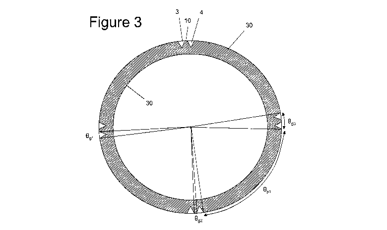
Figure 3 is a transverse sectional view taken along a line A-A in Figure 1;
Figure 4 is a close up transverse sectional view showing a pair of grooves;
Figure 5 is a perspective view showing a set of charges in use as a Bangalore
torpedo;
and
Figure 6 is a schematic sectional view showing the torpedo exploding.
DETAILED DESCRIPTION OF EMBODIMENT(S)

CA 02757111 2011-0&29
WO 2010/112900 PCT/GB2010/050514
3
An explosive charge 1 shown in Figure 1 comprises an elongate casing 2 with
grooves
3, 4 running along the external wall of the casing. Figure 3 is a transverse
sectional
view taken along a line A-A in Figure 1, which shows that there are four pairs
of
grooves distributed around the circumference of the casing. The grooves are
all
identical so only the pair 3, 4 will be described in detail with reference to
Figure 4.
Each groove is V-shaped with a depth d. Each groove locally reduces the
thickness of
the casing, so the thickness tl of the casing at the bottom of each groove is
less than
the thickness t2 in the un-grooved portion between adjacent pairs of grooves.
The grooves 3, 4 are separated from each other by a small non-grooved portion
10 of
the casing in which the thickness of the casing is substantially constant. The
grooves
3, 4 are relatively narrow, as is the width of the non-grooved portion 10
which
separates the groove 3 from the groove 4. Specifically, each groove subtends
an angle
Ogl of only about 4 and the edge-to-edge angular spacing Ogg between the
edges of
adjacent grooves within a pair is only about 2 . Therefore each pair subtends
an angle
Og3 between its two outer edges of about 10 , and the edge-to-edge angular
spacing Opl
(shown in Figure 3) between the edges of adjacent pairs of grooves is about 80
.
The internal wall of the casing is circular in cross-section for ease of
manufacture and
to maximise the space available for explosive material.
Referring to Figure 2, which is a longitudinal sectional view taken along the
line B-B
shown in Figure 1, the casing has an internally threaded head end 11 adapted
to be
screwed to the tail end of an adjacent charge, and an externally threaded tail
end 12
adapted to be screwed to the head end of an adjacent charge.
Figure 5 shows the device in use as a Bangalore torpedo being prepared to
clear a path
through a series of wires 20 (for instance barbed wire or razor wire). A
number of
casing units 21, 22 (in this case two, but optionally more than two) are
screwed
together head to tail. An explosive charge (not shown) is contained inside the
torpedo
along its full length. A nose cone 23 is screwed to the head end of the front
casing
unit, and a detonator housing 24 with an initiator is screwed to the tail end
of the rear
casing. The torpedo is fed under the barbed wire and placed on the ground with
two
pairs of grooves facing up and oriented at approximately +/- 45 to the
vertical.

CA 02757111 2011-0&29
WO 2010/112900 PCT/GB2010/050514
4
The charge is then detonated, causing the casing to break initially at the
bases of the
eight grooves where the thickness tl is at a minimum. The casing material
between
the grooves forms four small pre-defined fragments which are ejected at
approximately +/- 45 to the vertical. The fragments from the two downwardly
pointed pairs of grooves impact the ground and are not shown in Figure 6.
However
the fragments 25, 26 from the two upwardly pointed pairs of grooves are
ejected
upwardly and cut the barbed wire at locations 27 and 28 respectively, clearing
a path
through the obstacle. The relatively large volume of casing between the pairs
of
grooves generates a set of relatively small and low energy particles 29, 30,
31 which
have less cutting effect than the fragments 25, 26. Spacing the pairs of
grooves apart,
and making the spacing between adjacent grooves in a pair relatively small,
ensures
that the fragments 25, 26 have relatively high energy and cutting
effectiveness. It is
also believed that the tapering profile of the grooves (in this case a V-
shaped profile)
provides a focusing effect on the detonation wave.
Note that Figure 6 does not show the true shape of the fragments 25, 26 or
lower
energy particles 29-31 but merely intends to show the mode of operation
schematically.
Although the invention has been described above with reference to one or more
preferred embodiments, it will be appreciated that various changes or
modifications
may be made without departing from the scope of the invention as defined in
the
appended claims.

Dessin représentatif
Une figure unique qui représente un dessin illustrant l'invention.
États administratifs

2024-08-01 : Dans le cadre de la transition vers les Brevets de nouvelle génération (BNG), la base de données sur les brevets canadiens (BDBC) contient désormais un Historique d'événement plus détaillé, qui reproduit le Journal des événements de notre nouvelle solution interne.

Veuillez noter que les événements débutant par « Inactive : » se réfèrent à des événements qui ne sont plus utilisés dans notre nouvelle solution interne.

Pour une meilleure compréhension de l'état de la demande ou brevet qui figure sur cette page, la rubrique Mise en garde , et les descriptions de Brevet , Historique d'événement , Taxes périodiques et Historique des paiements devraient être consultées.

Historique d'événement

Description Date
Le délai pour l'annulation est expiré 2015-03-26
Demande non rétablie avant l'échéance 2015-03-26
Réputée abandonnée - omission de répondre à un avis sur les taxes pour le maintien en état 2014-03-26
Inactive : Réponse à l'art.37 Règles - PCT 2012-01-06
Inactive : Page couverture publiée 2011-11-29
Inactive : CIB attribuée 2011-11-17
Inactive : Demande sous art.37 Règles - PCT 2011-11-17
Inactive : Notice - Entrée phase nat. - Pas de RE 2011-11-17
Demande reçue - PCT 2011-11-17
Inactive : CIB en 1re position 2011-11-17
Inactive : CIB attribuée 2011-11-17
Exigences pour l'entrée dans la phase nationale - jugée conforme 2011-09-29
Demande publiée (accessible au public) 2010-10-07

Historique d'abandonnement

Date d'abandonnement Raison Date de rétablissement
2014-03-26

Taxes périodiques

Le dernier paiement a été reçu le 2013-03-13

Avis : Si le paiement en totalité n'a pas été reçu au plus tard à la date indiquée, une taxe supplémentaire peut être imposée, soit une des taxes suivantes :

  • taxe de rétablissement ;
  • taxe pour paiement en souffrance ; ou
  • taxe additionnelle pour le renversement d'une péremption réputée.

Veuillez vous référer à la page web des taxes sur les brevets de l'OPIC pour voir tous les montants actuels des taxes.

Historique des taxes

Type de taxes Anniversaire Échéance Date payée
Taxe nationale de base - générale 2011-09-29
TM (demande, 2e anniv.) - générale 02 2012-03-26 2011-09-29
TM (demande, 3e anniv.) - générale 03 2013-03-26 2013-03-13
Titulaires au dossier

Les titulaires actuels et antérieures au dossier sont affichés en ordre alphabétique.

Titulaires actuels au dossier
CHEMRING ENERGETICS UK LIMITED
Titulaires antérieures au dossier
COLIN DOUGLAS YOUNG
Les propriétaires antérieurs qui ne figurent pas dans la liste des « Propriétaires au dossier » apparaîtront dans d'autres documents au dossier.
Documents

Pour visionner les fichiers sélectionnés, entrer le code reCAPTCHA :


Pour visualiser une image, cliquer sur un lien dans la colonne description du document. Pour télécharger l'image (les images), cliquer l'une ou plusieurs cases à cocher dans la première colonne et ensuite cliquer sur le bouton "Télécharger sélection en format PDF (archive Zip)" ou le bouton "Télécharger sélection (en un fichier PDF fusionné)".

Liste des documents de brevet publiés et non publiés sur la BDBC .

Si vous avez des difficultés à accéder au contenu, veuillez communiquer avec le Centre de services à la clientèle au 1-866-997-1936, ou envoyer un courriel au Centre de service à la clientèle de l'OPIC.


Description du
Document 
Date
(aaaa-mm-jj) 
Nombre de pages   Taille de l'image (Ko) 
Dessin représentatif 2011-09-29 1 57
Dessins 2011-09-29 3 136
Description 2011-09-29 4 169
Revendications 2011-09-29 2 77
Abrégé 2011-09-29 1 73
Page couverture 2011-11-29 1 64
Avis d'entree dans la phase nationale 2011-11-17 1 194
Courtoisie - Lettre d'abandon (taxe de maintien en état) 2014-05-21 1 172
Rappel - requête d'examen 2014-11-27 1 117
PCT 2011-09-29 9 312
Correspondance 2011-11-17 1 19
Correspondance 2012-01-06 3 70