Note: Descriptions are shown in the official language in which they were submitted.
CA 027574522011-0&30
WO 2010/114849 PCT/US2010/029257
HYDROGEN GENERATION SYSTEMS AND METHODS UTILIZING SODIUM
SILICIDE AND SODIUM SILICA GEL MATERIALS
CROSS REFERENCE TO RELATED APPLICATION
[0001] This application claims benefit of priority of U.S. Provisional Patent
Application
Serial Number 61/164,888 filed on March 30, 2009, and U.S. Provisional Patent
Application
Serial Number 61/185,579 filed on June 6, 2009, the entire disclosures of
which are incorporated
herein by reference.
FEDERALLY-SPONSORED RESEARCH AND DEVELOPMENT
[0002] This invention was made with government support under contract number
DE-
FG36-08GO88108 awarded by the U.S. Department of Energy. The U.S. Government
has
certain rights in this invention.
TECHNOLOGICAL FIELD
[0003] This technology generally relates to systems and methods of generating
hydrogen
using a reactant fuel material and an aqueous solution, and more particularly,
to systems and
methods for generating hydrogen using sodium silicide, sodium silica gel, or
multi-component
mixtures when reacted with water or water solutions.
BACKGROUND
[0004] Fuel cells are electrochemical energy conversion devices that convert
an external
source fuel into electrical current. Many common fuel cells use hydrogen as
the fuel and oxygen
(typically from air) as an oxidant. The by-product for such a fuel cell is
water, making the fuel
cell a very low environmental impact device for generating power.
[0005] Fuel cells compete with numerous other technologies for producing
power, such
as the gasoline turbine, the internal combustion engine, and the battery. A
fuel cell provides a
direct current (DC) voltage that can be used for numerous applications
including: stationary
power generation, lighting, back-up power, consumer electronics, personal
mobility devices,
such as electric bicycles, as well as landscaping equipment, and others. There
are a wide variety
of fuel cells available, each using a different chemistry to generate power.
Fuel cells are usually
1
CA 027574522011-0&30
WO 2010/114849 PCT/US2010/029257
classified according to their operating temperature and the type of
electrolyte system that they
utilize. One common fuel cell is the polymer exchange membrane fuel cell
(PEMFC), which
uses hydrogen as the fuel with oxygen (usually air) as its oxidant. It has a
high power density
and a low operating temperature of usually below 80 C. These fuel cells are
reliable with
modest packaging and system implementation requirements.
[0006] The challenge of hydrogen storage and generation has limited the wide-
scale
adoption of PEM fuel cells. Although molecular hydrogen has a very high energy
density on a
mass basis, as a gas at ambient conditions it has very low energy density by
volume. The
techniques employed to provide hydrogen to portable applications are
widespread, including
high pressure and cryogenics, but they have most often focused on chemical
compounds that
reliably release hydrogen gas on-demand. There are presently three broadly
accepted
mechanisms used to store hydrogen in materials: absorption, adsorption, and
chemical reaction.
[0007] In absorptive hydrogen storage for fueling a fuel cell, hydrogen gas is
absorbed
directly at high pressure into the bulk of a specific crystalline material,
such as a metal hydride.
Most often, metal hydrides, like MgH2, NaA1H4, and LaNi5H6, are used to store
the hydrogen gas
reversibly. However, metal hydride systems suffer from poor specific energy
(i.e., a low
hydrogen storage to metal hydride mass ratio) and poor input/output flow
characteristics. The
hydrogen flow characteristics are driven by the endothermic properties of
metal hydrides (the
internal temperature drops when removing hydrogen and rises when recharging
with hydrogen).
Because of these properties, metal hydrides tend to be heavy and require
complicated systems to
rapidly charge and/or discharge them. For example, see U.S. Patent 7,271,567
for a system
designed to store and then controllably release pressurized hydrogen gas from
a cartridge
containing a metal hydride or some other hydrogen-based chemical fuel. This
system also
monitors the level of remaining hydrogen capable of being delivered to the
fuel cell by
measuring the temperature and/or the pressure of the metal hydride fuel itself
and/or by
measuring the current output of the fuel cell to estimate the amount of
hydrogen consumed.
[0008] In adsorption hydrogen storage for fueling a fuel cell, molecular
hydrogen is
associated with the chemical fuel by either physisorption or chemisorption.
Chemical hydrides,
like lithium hydride (LiH), lithium aluminum hydride (LiA1H4), lithium
borohydride (LiBH4),
sodium hydride (NaH), sodium borohydride (NaBH4), and the like, are used to
store hydrogen
2
CA 027574522011-0&30
WO 2010/114849 PCT/US2010/029257
gas non-reversibly. Chemical hydrides produce large amounts of hydrogen gas
upon its reaction
with water as shown below:
NaBH4 + 2H20 - NaB02 + 4H2
To reliably control the reaction of chemical hydrides with water to release
hydrogen gas from a
fuel storage device, a catalyst must be employed along with tight control of
the water's pH.
Also, the chemical hydride is often embodied in a slurry of inert stabilizing
liquid to protect the
hydride from early release of its hydrogen gas. The chemical hydride systems
shown in U.S.
Patents 7,648,786; 7,393,369; 7,083,657; 7,052,671; 6,939,529; 6,746,496; and
6,821,499,
exploit at least one, but often a plurality, of the characteristics mentioned
above.
[0009] In chemical reaction methods for producing hydrogen for a fuel cell,
often
hydrogen storage and hydrogen release are catalyzed by a modest change in
temperature or
pressure of the chemical fuel. One example of this chemical system, which is
catalyzed by
temperature, is hydrogen generation from ammonia-borane by the following
reaction:
NH3BH3 - NH2BH2 + H2 - NHBH + H2
The first reaction releases 6.1 wt.% hydrogen and occurs at approximately 120
C, while the
second reaction releases another 6.5 wt.% hydrogen and occurs at approximately
160 C. These
chemical reaction methods do not use water as an initiator to produce hydrogen
gas, do not
require a tight control of the system pH, and often do not require a separate
catalyst material.
However, these chemical reaction methods are plagued with system control
issues often due to
the common occurrence of thermal runaway. See, for example, U.S. Patent
7,682,411, for a
system designed to thermally initialize hydrogen generation from ammonia-
borane and to protect
from thermal runaway. See, for example, U.S. Patents 7,316,788 and 7,578,992,
for chemical
reaction methods that employ a catalyst and a solvent to change the thermal
hydrogen release
conditions.
[0010] In view of the above, there is a need for an improved hydrogen
generation system
and method that overcomes many, or all, of the above problems or disadvantages
in the prior art.
3
CA 027574522011-0&30
WO 2010/114849 PCT/US2010/029257
SUMMARY
[0011] The hydrogen generation system described below accomplishes a
substantially
complete reaction of reactant fuel material, such as a stabilized alkali metal
material, including
sodium silicide and/or sodium-silica gel, which do not contain any stored
hydrogen gas or
molecular hydrogen atoms. Additional reactants can include sodium borohydride
(NaBH4),
and/or ammonia borane, and the like. Also, the system reaction employing these
reactants does
not require an additional catalyst chamber, and is easily start-stop
controlled by the simple
addition of an appropriate aqueous medium to satisfy the hydrogen demand of a
fuel cell or
hydrogen-drawing system. In addition, the examples below meet all of the above
requirements
while minimizing overall system volume and weight.
[0012] One example in the present disclosure is a reactor including a reactant
fuel
material, which generates hydrogen when the reactant fuel material is exposed
to an aqueous
solution. The reactor may be a standalone hydrogen generation component which
can contain
the aqueous solution. Similarly, another example can include a reactor to
which an aqueous
solution is introduced by an external supply. The hydrogen generation may also
be controlled,
monitored, or processed by an external control system. The control system and
reactor can
operate as a standalone hydrogen generation system used to provide hydrogen to
hydrogen fuel
cells or for any general, laboratory, industrial, or consumer use. Likewise,
the control system
and reactor can be implemented in whole or in part within a complete fuel cell
system supplying
an end product such as a laptop computer, personal or commercial electronics
products, and
other devices and equipment that require a power source.
[0013] One method of generating hydrogen gas includes inserting a reactant
fuel material
into a reactor and combining an aqueous solution with the reactant fuel
material in the reactor to
generate hydrogen gas.
[0014] The reactant fuel material can include stabilized alkali metal
materials such as
silicides, including sodium silicide powder (NaSi), and sodium-silica gel (Na-
SG). The
stabilized alkali metal materials can also be combined with other reactive
materials, including,
but not limited to, ammonia-borane with, or without, catalysts, sodium
borohydride mixed with,
or without, catalysts, and an array of materials and material mixtures that
produce hydrogen
when exposed to heat or aqueous solutions. The mixture of materials and the
aqueous solutions
can also include additives to control the pH of the waste products, to change
the solubility of the
4
CA 027574522011-0&30
WO 2010/114849 PCT/US2010/029257
waste products, to increase the amount of hydrogen production, to increase the
rate of hydrogen
production, and to control the temperature of the reaction. The aqueous
solution can include
water, acids, bases, alcohols, and mixtures of these solutions. Examples of
the aqueous solutions
can include methanol, ethanol, hydrochloric acid, acetic acid, sodium
hydroxide, and the like.
The aqueous solutions can also include additives, such as a coreactant that
increases the amount
of H2 produced, a flocculant, a corrosion inhibitor, or a thermophysical
additive that changes
thermophysical properties of the aqueous solution. Example flocculants include
calcium
hydroxide, sodium silicate, and others, while corrosion inhibitors can include
phosphates,
borates, and others. Further, the thermophysical additive can change the
temperature range of
reaction, the pressure range of the reaction, and the like. Further, the
additive to the aqueous
solution can include mixtures of a variety of different additives.
[0015] The reactor can be a standalone, replaceable component, which enables a
control
system or a fuel cell system to utilize multiple reactors. The reactor may
also be termed a
cartridge, cylinder, can, vessel, pressure vessel, and/or enclosure. The
reactor includes the
reactant fuel material and either the aqueous solution inside the reactor or
an inlet port, or a
plurality of inlet ports, from which the aqueous solution is introduced into
the reactor. The
reactor can also have an output port for hydrogen gas, which may undergo
additional processing
(e.g., vapor condensation, purification, regulation, and the like) once it
leaves the reactor and
prior to being supplied to an external system, like a fuel cell.
[0016] The aqueous solution may be initially stored or added by the user
externally or
returned from a fuel cell system into the aqueous solution input port on the
reactor. The aqueous
solution can be added to the reactant fuel material, including stabilized
alkali metals, in the
reactor via the inlet port(s) using a pump, such as a manual pump, a battery
powered pump, an
externally powered pump, a spring controlled pump, and the like. The aqueous
solution can be
stored within the reactor and separated from the reactant fuel material by a
piston, bag,
membrane, or other separation device.
[0017] The reactor may have the hydrogen output and the aqueous solution input
as part of
one connection to one device or control system. The reactor may have the
hydrogen output
connected to one device or control system and the water input connected to a
different device or
control system. The reactor may have only a hydrogen output with internal
controls combining
the reactant fuel material with the aqueous solution.
CA 027574522011-0&30
WO 2010/114849 PCT/US2010/029257
[0018] The method of generating hydrogen gas can also include filtering the
generated
hydrogen gas, absorbing by-products in the hydrogen gas, and/or condensing
water from the
generated hydrogen gas. This filtration can occur inside the reactor, inside
the control system, or
in both. For example, a hydrogen separation membrane can be used in either the
reactor or in the
control system (or in both) to filter the hydrogen, while a condenser unit can
be used to condense
the water from the generated hydrogen gas. Filters and condensers can act upon
the generated
hydrogen gas as it exits the hydrogen outlet port of the reactor. The filtered
hydrogen gas and/or
the condensed water can be recycled back to the reactor or to a water storage
container. In
generating hydrogen gas, a waste product can be created, such as sodium
silicate or other
reaction waste products.
[0019] In one example, a control system can include a monitoring device to
monitor
parameters of the reaction of the reactant fuel material and the aqueous
solution in the reactor.
The monitoring device can monitor one or multiple parameters in or on the
reactor or in an
external control system. These parameters can include, but are not limited to,
temperature,
electrical conductivity of the reactor contents, pressure in the reactor,
weight of reaction, amount
of un-reacted reactant fuel material, elapsed time of reaction, amount of
aqueous solution in the
reactor, and a maximum amount of aqueous solution to be added to the reactor.
The monitored
system characteristic can then be displayed, or used in a calculation to
modify the control
strategy, communicate the reactor status or system status with other devices,
or communicate the
characteristic or a derivative characteristic to a user. An example of a user
communication
device is a visual display device, such as an LCD display, for example.
[0020] The reaction can be controlled in association with the monitoring
device using a
reaction control device. Examples of reaction control devices include, but are
not limited to,
devices to alter temperature, electrical conductivity range, pressure, weight
of reaction, as well as
other environmental measures within which the combination of the reactant fuel
material and the
aqueous solution in the reactor proceed. For example, reaction control devices
can be used to
add additional reactant fuel materials to the reactor, add additional aqueous
solution to the
reactor, remove a waste product from the reactor, cool the reactor, heat the
reactor, mix a
combination of the reactant fuel materials and the aqueous solution, bleed the
reactor to decrease
the pressure, and to perform other control measures.
6
CA 027574522011-0&30
WO 2010/114849 PCT/US2010/029257
[0021] Measuring reaction parameters and using reaction control devices allows
the
method of generating hydrogen gas to be controlled in the reactor when any of
the environmental
measures within the reactor is outside a respective range or by a control
strategy that monitors
and processes the rate of change of any of the parameters.
[0022] The reactor can include a number of different filters to separate the
reactants and its
reaction by-products from the hydrogen gas. For example, the methods of
generating clean
hydrogen gas can include both separating and filtering steps. In one example,
at least one of the
reactant fuel materials, the aqueous solution, the hydrogen gas, and/or the
reaction waste
products are separated from the others. Also, the hydrogen gas can be purified
using a hydrogen
separation membrane, a chemical filter, a desiccant filter, a coarse media
filter, a dryer filter,
and/or a secondary reactor chamber. As they are used, the filters can be
cleaned with a portion
of the aqueous solution as the aqueous solution is inputted into the reactor.
[0023] The reactor can also include structures and devices for aqueous
solution
distribution such as a plumbing network, nozzle arrays, flow limiters, and
water distribution
media such as diffusers, misters, and the like. The aqueous solution can be
distributed through
multiple points in the reactor in parallel, in series, or in a combination
thereof. The aqueous
solution distribution system can be used in whole, or in part, to react with
the reactant fuel
material to produce hydrogen, to purify the hydrogen stream, to clean filter
media, and/or to
control the waste product parameters.
[0024] The reactor can include hydrogen handling components such as a safety
relief
mechanism such as a relief valve, burst disc, or a controlled reactor burst
point. The reactor may
also include an exit flow limiter to minimize, or control, the hydrogen output
rate in order to
supply a required fuel cell characteristic or to match the transient flow rate
limitations of the
filtration components.
[0025] The system of generating hydrogen gas can also include a pressure
transducer, a
relief valve, a hydrogen-sealing check valve, a fan, a heat exchanger, and a
reactor cooling
source. Likewise, the system can include a recapture container for recycling
fuel cell reaction
waste solution and returning the recycled fuel cell reaction waste solution to
the reactor.
[0026] The methods of generating hydrogen can also include directing a portion
of the
aqueous solution to areas of the reactor to recapture the waste product
resulting from the
combination of the reactant fuel material and the aqueous solution. For
example, a portion of the
7
CA 027574522011-0&30
WO 2010/114849 PCT/US2010/029257
aqueous solution can be added to a secondary reactor chamber, and the
generated hydrogen gas
can be passed through this portioned aqueous solution. Filtering can also be
performed using a
liquid permeable screen to separate a waste product from un-reacted reactant
fuel material and
aqueous solution.
[0027] These and other advantages, aspects, and features will become more
apparent from
the following detailed description when viewed in conjunction with the
accompanying drawings.
Non-limiting and non-exhaustive embodiments are described with reference to
the following
drawings. Accordingly, the drawings and descriptions below are to be regarded
as illustrative in
nature, and not as restrictive.
BRIEF DESCRIPTION OF THE DRAWINGS
[0028] FIGURE 1 shows an example of a hydrogen generation system using a
stabilized
alkali metal material and an aqueous solution to provide hydrogen to a
hydrogen fuel cell or a
general laboratory, industrial, or consumer use.
[0029] FIGURE 2 illustrates an example of a hydrogen generation system with
two
reactors and a carry-handle accessory.
[0030] FIGURE 3 shows an example hydrogen gas generation system that includes
a
reactor, a water container, and a number of additional components
[0031] FIGURES 4A-4D illustrate reactors employing multiple water dispensing
nozzles
at select locations.
[0032] FIGURE 5 schematically illustrates an example hydrogen generation
system with a
heat removal structure.
[0033] FIGURE 6 shows an example hydrogen generation system with a hydrogen
outlet
and water inlet at one end of the reactor in a downward orientation to mix the
reaction
components.
[0034] FIGURE 7 shows an exploded view of a hydrogen generation system with
the heat
removal structure shown in FIGURES 5 and 6.
[0035] FIGURE 8 shows a hydrogen generation system configuration with a coarse
media
filter and a hydrogen filtration membrane.
[0036] FIGURES 9A-9C illustrate a water feed network and a comparison of
filter areas
without a water feed network and those utilizing the water feed network.
8
CA 027574522011-0&30
WO 2010/114849 PCT/US2010/029257
[0037] FIGURES 10-10B illustrate alternative filter designs to a
membrane/coarse filter
system.
[0038] FIGURES 11A-I IB illustrate systems and techniques of waste capture and
circulation.
[0039] FIGURE 12A illustrates an example of a reactor with multiple reaction
compartments.
[0040] FIGURE 12B illustrates an example reactor with multiple protective
insulation
devices.
[0041] FIGURE 13 illustrates an example reactor with electrical contacts to
measure
changes in conductivity.
[0042] FIGURE 14 illustrates an example reactor with electrical contacts
connected to a
pressure vessel cap of the reactor.
[0043] FIGURES 15A-15C shows an example lightweight, low-cost, reusable
reactor in
accordance with the claimed invention.
[0044] FIGURE 16 shows an example architecture of a low output reactor system
in
accordance with the claimed invention.
[0045] FIGURE 17 shows a detailed example of a low output reactor system in
accordance
with the claimed invention.
[0046] FIGURE 18 shows a reactor with solid reactant fuel material connected
by a valve
to a spring-based liquid pump system.
[0047] FIGURE 19 shows a graphical depiction of oscillatory hydrogen
generation over
time in a spring-based liquid pump system without a coupling valve
[0048] FIGURE 20 shows a graphical depiction of hydrogen generation pressure
over time
in a spring-based liquid pump system with a coupling valve.
[0049] FIGURE 21 shows a reactor with reactant fuel material and a spring
based liquid
pump system integrated within a single cartridge.
[0050] FIGURE 22A shows a reactor with reactant fuel material and an
integrated spring
based liquid pump system.
[0051] FIGURE 22B shows three primary sub-assemblies of an integrated
cartridge with a
reactor and spring based liquid pump system.
9
CA 027574522011-0&30
WO 2010/114849 PCT/US2010/029257
[0052] FIGURE 23 shows a perspective view and cross-section of an integrated
cartridge
with a reactor and spring based liquid pump system
[0053] FIGURE 24 shows an assembly view of an integrated cartridge
[0054] FIGURE 25 illustrates water feed distribution mechanisms.
[0055] FIGURE 26 shows a threaded locking mechanism to couple a separable
liquid
feed/reactor hydrogen generation device.
[0056] FIGURE 27 shows a schematic representation of a separable liquid
feed/reactor
hydrogen generation device.
[0057] FIGURE 28 shows a schematic representation of a separable liquid
feed/reactor
hydrogen generation device with a conical/collapsing spring
[0058] FIGURES 29A-29B depict normal and compressed views of a collapsible
spring to
facilitate limited variability in force over travel.
[0059] FIGURE 30A shows a perspective view of a hydrogen generation cartridge
with a
spring based liquid feed and a volume exchanging system
[0060] FIGURE 30B shows a schematic representation of a hydrogen generation
cartridge
with a spring based liquid feed and a volume exchanging system.
[0061] FIGURE 31 shows perspective and cross-sectional views of a hydrogen
generation
cartridge with a volume exchanging, spring based liquid feed.
[0062] FIGURE 32 shows an assembly view and a cross-sectional view of a
hydrogen
generation cartridge with volume exchanging, spring based liquid feed.
[0063] FIGURE 33 shows an assembly view of an integrated cartridge filtration
system
example.
[0064] FIGURE 34 shows an assembly view of a normally closed valve to separate
a
reactor and a liquid feed.
[0065] FIGURES 35A-B show an assembly view and a perspective view of a mating
component to join a reactor and a liquid feed.
DETAILED DESCRIPTION
[0066] In the examples below, reference is made to hydrogen fuel cell systems,
but it
should be understood that the systems and methods discussed can also be
implemented in any
CA 027574522011-0&30
WO 2010/114849 PCT/US2010/029257
hydrogen gas generation application, such as laboratory applications,
commercial or industrial
applications, and consumer applications, for example.
Basic Hydrogen Control System
[0067] In one example, sodium silicide and/or sodium silica gel can be
combined with
water to generate hydrogen gas, but the developed technologies can also use
other stabilized
alkali metal materials, such as doped silicides and silicides that have
hydrogen in association, or
solid powders combined with aqueous solutions to produce hydrogen gas.
Additionally, many
aspects of the developed system technology can also be applied to alternative
materials used in
hydrogen production such as aluminum powder, or any other material, or
combination of
materials, that generates hydrogen when exposed to aqueous solutions.
[0068] The reactant fuel materials can be free-flowing powders or materials
that are
compressed, molded, cut or formed into rods, cones, spheres, cylinders or
other physical
geometries. The materials may consist of variable powder sizes, geometric
variations, material
coatings, or material variations to control the reaction rate. One method for
coating would be to
expose the solid sodium silicide structure to humid air creating a sodium
silicate barrier which is
dissolvable in water. Of course other forms and geometries for the reactant
fuel materials and
aqueous solutions may be used with which to combine the reactant fuel
materials and aqueous
solutions.
[0069] FIGURE 1 shows an example of a hydrogen generation system 100 using a
reactant
fuel material and an aqueous solution to generate hydrogen gas. The generated
hydrogen gas can
be directed to a hydrogen fuel cell or to a general laboratory, industrial, or
consumer use. The
reactant fuel material 101 can be inserted into a reactor 102. In this
disclosure, the terms reactor,
cartridge, and pressure vessel are used synonymously to identify a container
or other receptacle
in which a reactant fuel material is placed. In the example shown in FIGURE 1,
a removable
reactor 102 is attached to a water inlet connection 106 and a hydrogen outlet
connection 108.
The connections can include, but are not limited to, normally-closed double-
shut-off valves
and/or normally closed check valves. The connections from the reactor 102 to
the water inlet
connection 106 and hydrogen outlet connection 108 can be flexible connections
or can be rigid
connections, depending upon the particular use. Water, or another aqueous
solution, is added to
the reactant fuel material, such as a stabilized alkali metal 101 to generate
hydrogen gas and a
11
CA 027574522011-0&30
WO 2010/114849 PCT/US2010/029257
by-product, such as sodium silicate. The hydrogen gas moves upward and exits
the reactor 102.
Although a single reactor 102 is illustrated in FIGURE 1, it should be
understood that any
number of removable or fixed reactors can be used in the exemplary hydrogen
gas generation
systems described. For example, in FIGURE 2, two removable reactors 202, 204
are shown.
Further, the reactors can be secured in place in the system using a locking
mechanism, a clip, or
other similar securing device.
[0070] In the example shown in FIGURES 1 and 2, an aqueous solution, like
water, is
added to fill ports 110, 210, respectively. In another implementation, a
removable water
container can be used, such as water container 114, with or without a fill
port. In other
examples, a reactor can be pre-filled with reactant fuel material. The aqueous
solution can
include additives to improve reaction efficiencies, increase hydrogen
production, increase the
rate of hydrogen production, reduce contaminant formation, facilitate
contaminant filtration,
support final hydrolysis, reduce corrosion, control the pH of the waste
products, change the
solubility of the waste products, and extend temperature range operation, as
well as affect other
reaction parameters such as the thermophysical properties of the reactants.
For example, the
additives can include acids, bases, alcohols, other additives, and mixtures of
these additives.
Examples of the additives can include methanol, ethanol, hydrochloric acid,
acetic acid, sodium
hydroxide, calcium hydroxide, sodium silicate, phosphates, borates, and
others. Other additives
can be combined with the reactant fuel material, including boron, carbon, and
nitrogen to
improve the hydrogen capacity, kinetics and/or to reduce reaction enthalpy.
With regard to
temperature range operation, salt and/or other additives can be included in
the aqueous solution
to reduce the freezing point of the solution.
[0071] The amount of aqueous solution stored in its container can vary
depending on
system implementation specifics. For example, in FIGURE 2, the container can
store more than
a sufficient volume of aqueous solution to react multiple cartridges 202, 204.
The system can
include a condenser (not shown) to condense water from the hydrogen output
stream and either
return it directly to the reactor, or direct it to the water container 114.
The system can include a
water inlet connection 106 for an external water source (not shown) to supply
additional water to
the water container 114, or in a separate implementation directly to the
reactor. In one
implementation, fuel cell reaction waste water can be captured in full or in
part and also
contribute to the water supply to reduce the net total water requirements.
12
CA 027574522011-0&30
WO 2010/114849 PCT/US2010/029257
[0072] For example, the sodium silicate waste product readily absorbs water,
and its
viscosity changes accordingly. By separating the waste product from the un-
reacted reactant fuel
material, the reaction can be controlled. For example, one end of the reactor
can be heated or
insulated to create a solubility condition where excess water exists. This
water can then either be
pumped back up to the stabilized alkali metal powder or allowed to react with
an amount of
sodium silicide configured exclusively for water usage maximization.
Alternatively, at the point
of reaction, the waste silicate is warm requiring little water to be in a
liquid phase. At the point
of reaction, a separation screen is utilized to separate the liquid waste from
the unreacted reactant
fuel material.
Additional System Components
[0073] In addition to the reactor and the aqueous solution sources, the
hydrogen gas
generation systems can include additional system components. For example,
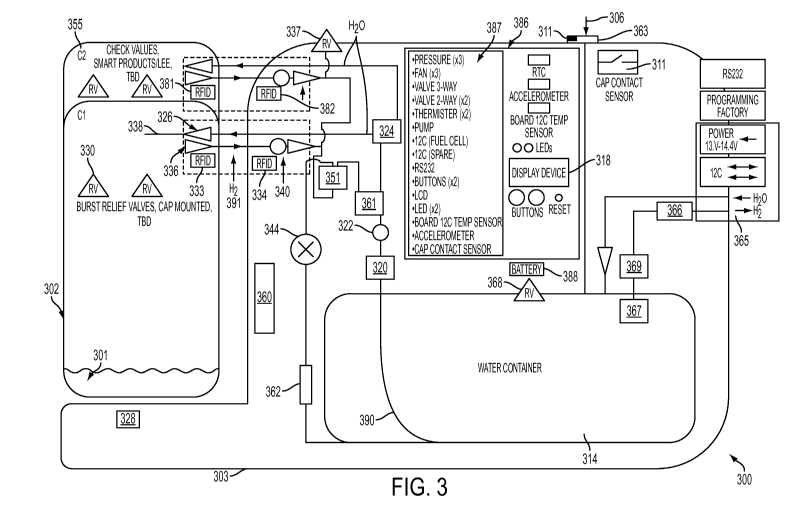
FIGURE 3 shows
an example hydrogen gas generation system 300 that includes a reactor 302, a
water container
314, and a number of additional components. For example, water source inlet
306 allows the
filling, or refilling, of water container 314 as needed. Water from water
container 314 may be
pumped into reactor 302 via water supply line 390 using a pump 320, such as a
peristaltic pump,
a manual pump, positive displacement pumps, and other pumps. A pressure
transducer 322 may
be placed in line with water supply line 390 and used to regulate the amount
of water pumped
into the reactor 302. For example, pressure transducer 322 may be used with a
pump 320 to
deliver pressure calibrated amounts of water to multiple reactors through a
multiport valve 324.
Pressure transducer 322 may also be used in part to provide a fail-safe mode
to prevent excess
water from being pumped into the reactor 302. In one example, the output
voltage of pressure
transducer 322 can be compared to a system voltage parameter using a
comparator (not shown).
The output of the comparator can be evaluated to determine if the voltage is
in a proper
operational range. When the voltage is in the operational range, additional
circuitry
implementing instructions from microcontroller 387 can drive pump 320 to
provide water to the
reactor 302. When the voltage is outside the operational range, the pump 320
is disabled. This
circuitry can use a capacitor, or other timing circuits, to create a delay in
the reading of the pump
to allow an instantaneously high reading during a diaphragm pump action for
example. For
13
CA 027574522011-0&30
WO 2010/114849 PCT/US2010/029257
hydrogen generation systems with multiple reactors, a supply valve 324 can be
used to select
which reactor receives water.
[0074] The hydrogen gas generation system 300 can include a battery 388 to
operate the
pump 320 and/or to otherwise initiate the reaction and to operate other
control electronics
(shown collectively as 386). The hydrogen gas generation system 300 can also
receive external
power to either recharge the battery 388 from any external source such as a
fuel cell, a wall
outlet, or power from any other source. The system 300 may also include a
small fuel cell
system (not shown) to internally operate its internal balance-of-plant
components. In one
implementation, no battery is present in isolation, but rather power is
obtained from a fuel cell or
a fuel cell battery hybrid that is either internal to the overall system 300
or external to the
hydrogen generation system 300. In one implementation, no battery is required
if the reactors
are given a factory over-pressure of hydrogen, which provides enough hydrogen
to start the
system. Furthermore, the hydrogen generation system can be designed with a
small manually
operated pump (such as a syringe or the like) to start the reaction by a
physical user interaction
rather than an electrical start.
[0075] Similar to pressure transducer 322, a check valve 326 can be used in
the reactor
302, or in the control system, to keep hydrogen pressure in reactor 302 from
pushing
unallowably high pressures on control system components such as valves 324 /
361, transducer
322, and/or pumps 320. For example, as the initial water enters the reactor
302 and reacts with
reactant fuel material 301 in the reactor 302, hydrogen is generated, and the
hydrogen pressure in
the reactor 302 builds until the hydrogen reaches a system pressure parameter
value upon which
the hydrogen gas is routed out of the reactor 302 and is used elsewhere. In
some situations, the
pressure in the reactor 302 can exceed that of the capabilities of the pump
320 and other system
components. Check valve 326 can be used to prevent the pump 320, water
container 314, and
water line 390 from becoming excessively pressurized and to prevent damage to
the system.
Check valve 326 can be used to determine the pressure in the reactor 302 and
to isolate the
amount of pressure to the control system from the reactor 302.
[0076] Similarly, hydrogen output check valves 336, 337 manage backflow in the
reactor
302. Backflow may occur when the system is used at high altitudes or when the
hydrogen
outputs of multiple canisters are tied to each other. Check valves and
transducers in each reactor,
and throughout the control system, allow for independent pressure readings of
each reactor for
14
CA 027574522011-0&30
WO 2010/114849 PCT/US2010/029257
systems that use multiple reactors. The hydrogen gas output lines 391 from
each reactor 302 can
include a pressure transducer 340, located in the reactor 302 or in the
control system 303. In one
implementation, the check valve 336 only allows hydrogen to flow out of the
canister as opposed
to air entering the canister when being connected and disconnected, or in the
event that the
system is inadvertently connecting high pressure from another source to a
reactor. In another
implementation, this check valve 336 is not required but a normally closed
check valve 3430 (as
shown in FIGURE 34) is used alternatively. In one implementation, check valves
are connected
downstream of pressure transducers 340 which allow one reactor from back-
pressuring another
reactor while providing independent pressure readings of each reactor with the
pressure
transducers residing in the control system. In other implementations, the
check valves 326, 336
can physically reside in the reactor 302 or in the control system 303 and
provide the same
function. Additionally, the system can also include a pressure regulator 344.
At times, it may be
desired to operate the reactor 302 at a higher pressure (e.g., 80 psi or
higher). In one example,
the regulator 344 can bring the pressure down to 25 psi. Alternatively, a
regulator 344 with a
dial, or other means of regulating pressure, can be used, which would allow a
user to change the
output pressure of the control system. Alternatively, an electronically
controlled regulator can be
used to allow a microcontroller (such as microcontroller 387) to set the
output pressure based on
the desired pressure. In a separate implementation, no regulator could be used
at all, and the
micro-controller could control the water flow rate and amount to control the
output pressure of
the reactor.
Material Feeds
[0077] Alternative reactant fuel material (e.g. sodium silicide) / liquid
(e.g. water)
mechanisms are possible. In some configurations, the reactant material can be
formed, molded,
or pressed into geometrical structures. For example, rods formed from
stabilized alkali metal
materials can be inserted into an aqueous solution at a defined rate to
control the reaction.
Similarly, the rod may simply be removed from the water bath, or other aqueous
solution, to stop
the reaction. Additionally, reactant fuel materials can also be compressed
into pellets. These
pellets can then be manipulated and placed into water, or other aqueous
solutions, at a defined
rate to effect the reaction.
CA 027574522011-0&30
WO 2010/114849 PCT/US2010/029257
Aqueous Solution Feeds
[0078] Water may be fed into reactor 302 in a number of different ways. For
example,
water can be fed into the reactor using a single water inlet 338, or by using
multiple water
dispensing nozzles at select locations as shown in FIGURES 4A-4D. In simple
system
configurations and for small systems, a single water input will suffice. For
larger systems,
multiple water inputs can be used to facilitate the reaction and to aid in a
reaction re-start. For
example, in FIGURE 4A, a water feed tube 411 extends vertically from water
inlet 406 and
employs multiple water dispensing nozzles 413 with which to feed water to
multiple areas of the
reactor 402 using a single tube 411. Likewise in FIGURE 4B, a horizontal water
dispensing
filter spray 415 is also used to feed water to multiple areas of the reactor
402. In practice, a
single or any number of tubes can be used. The tubes and water dispensing
nozzles may be of
varied sizes, and the water dispensing nozzle pattern and hole size may vary
across the tube to
optimize the reactor mixing conditions. For example, small tubing may be used
with a number
of small holes, such as holes with dimensions of .001" to .040" or larger in
diameter, for
example. Small holes can have a tendency to clog with reaction by-products
when attempting to
restart a reaction, while larger nozzles can cause the aqueous solution to
dribble onto the reactant
fuel material rather than jet or mist. When using a pump with high pressure
capability, larger
orifices can be used to inject water to the point of reaction. When low
pressure water feed
system are used, more nozzles can be used to limit the distance between the
nozzle and points of
reaction. Depending upon the application and the specific reactants, any of
the aqueous solution
delivery techniques can be selected.
[0079] Additionally, the water feed tubes may be curved or spiraled as shown
in
FIGURES 4C and 4D. In FIGURES 4C and 4D, a spiral water feed tube 421 can be
used to
access multiple areas of the reactor 402 using a single tube. This spiral
water feed tube 421 can
have holes in a number of possible positions to maximize its coverage area and
to minimize
water saturation in one area of the reactor 402 with respect to another. The
center post 423 can
also be included for mechanical support and for heat removal. For designs that
do not require
such support or heat removal structures, it can be removed. Additionally, a
water feed network
can be integrated within the center post 423. Other water dispersion
configurations are possible
as well. For example, one implementation can employ an assortment of fine
holes or mesh to
facilitate water transfer. In other implementations, the water feed network
may not be uniform
16
CA 027574522011-0&30
WO 2010/114849 PCT/US2010/029257
through the volume of the canister. For example, the feed network can be
optimized to feed
directly into the reactant fuel area. If a reactor has an excess volume for
waste products or
reactant foaming, the water feed network may not add water to these areas.
Additionally, the
water feed network can employ tubing configured to spray water on a
membrane(s) used for
hydrogen separation (discussed below). The tubing can include holes or it may
contain
additional array(s) of tube(s) or nozzles. In this manner, water is fed
directly to the reactant fuel
in multiple areas of the reactor 402 to facilitate its reaction with the
aqueous solution.
[0080] By feeding water into select locations of the reactor 402, the water
and ensuing
reaction can be made to churn or mix the reactant fuel in the reactor 402. As
hydrogen is formed
and rises, the hydrogen gas serves to stir the reactor materials (that is, the
aqueous solution and
the reactant fuel materials) enabling near complete reactivity of these
reaction components.
Mixing the reaction components can also be accomplished by positioning both
the hydrogen
outlet and water inlet on one end of the reactor with downward orientation as
shown in FIGURE
6. This configuration provides a single connection plane to the hydrogen
generation system.
The hydrogen pickup 666 is located at the top of the reactor 602 and the
pressurized gas travels
to the bottom through a hydrogen tube 668. This hydrogen tube 668 can be in or
outside the
reactor. Different configurations and tube geometries can also be employed.
[0081] Less than complete reactivity can be employed, which may increase
energy density
(H2 delivered / (mass of powder + mass of water required)) as the amount of
water required is
non-linear. In addition, partial reactivity can leave the waste product in a
near solid state as it
cools from the elevated local reaction temperature. Solid waste products can
be beneficial for
waste material disposal.
Heat Transfer
[0082] Returning to FIGURE 3, as the reaction of the reactant fuel material
301 and water
progress, heat is generated inside the reactor 302. One or more thermisters
328 can be used to
measure the heat of the reactor 302 and to control a cooling system, including
one or more
cooling fans 330 that can be used to cool the reactor 302. Likewise, cooling
may be provided by
a liquid cooling loop (not shown) using a self-contained heat management
circuit, or by
circulating water about the reactor 302 from the water container 314 using a
separate water
cooling run. Of course, thermister 328 may also control water supply valve 324
to regulate water
17
CA 027574522011-0&30
WO 2010/114849 PCT/US2010/029257
flowing into reactor 302 to control the reaction based upon the temperature of
reactor 302, to
control the amount of waste product generated, to minimize water usage, to
maximize reactivity,
and for other reasons.
[0083] As shown in FIGURE 5, a heat removal structure 523 can be positioned in
the
center of the reactor 502 as well. The heat removal structure 523 may also
facilitate a
mechanical reactor locking mechanism by holding both ends of the reactor
together when
pressurized.
[0084] In FIGURE 5, the bottom 572 of the reactor also serves as a heat sink
and stand for
the reactor 502. While some heat is removed through the reactor walls, when
these walls are
clear and made from glass or plastic, these materials typically have limited
thermal conductivity.
In one implementation, a significant amount of heat is removed through either
or both ends 562,
572 of the reactor. One end of the reactor 502 may exclusively be a heat sink
(bottom 572) while
the other end (top cap 562) may contain the reactor control and connections
such as hydrogen
connectors 508 and water connectors 506, relief valves 555, electrical
connections 577, 579 such
as electrical feed-thru, electrical signal processing connections, system
sensing connections, and
structural connections. In FIGURE 5, the entire body of the reactor 502 can be
clear or
translucent (e.g., made of glass or plastic), providing both a feature
allowing for visual detection
of the status of the reaction, an estimate of reactant fuel material
consumption, as well a unique
packaging and visual appearance. In another implementation, the reactor can be
generally
opaque with a clear viewing window with which to view the reaction.
[0085] Additionally, as shown in the example of FIGURE 7, the heat sink 723
and all
components are connected on one end 762. This geometry facilitates easy
connection to the
hydrogen generation system with gas connections 708, fluid connections 706,
and electrical
connections 777, while providing a direct path for heat removal by the
hydrogen generation
system using air cooling, liquid cooling, or any other method.
Pressure Control
[0086] Returning to FIGURE 3, burst relief valves, burst disks, or other
controlled
pressure relief points 330 can be implemented in the reactor 302 to control
its pressure. For
example, when the pressure in the reactor 302 reaches a predetermined system
parameter,
hydrogen gas could be controllably vented from the reactor 302 through a
pressure relief point
18
CA 027574522011-0&30
WO 2010/114849 PCT/US2010/029257
330. In one example, a flow limiter can be used to limit the hydrogen output
flow, to keep the
flow within an allowable range for downstream devices, and/or to keep the flow
within the
allowable rate for successful filtration. The flow limiter can be an orifice
or a function of the
check valve components. A flow limiter that limits water input to the reactor
can be employed to
avoid excessive instantaneous pressure generation.
[0087] The hydrogen generation system 300 can be configured to operate over a
range of
pressures. In one implementation, a user can set the desired pressure limit,
or range, using
buttons, switches, or any other communications protocol (e.g., Bluetooth and
the like) either
directly or remotely. In one implementation, the system 300 will monitor the
pressure and
control the reaction accordingly to maintain that pressure in the reactor 302
within a prescribed
tolerance band. The system 300 can be used for lower pressure applications (on
the order of 25
psi) to facilitate user safety and operational simplicity. Many fuel cell
applications operate in
this pressure range. However, when necessary, sodium silicide can generate
1000's of psi for
applications that require it.
Hydrogen Filtration
[0088] In one implementation, the reactant fuel material is sodium silicide,
which is
combined with an aqueous solution to form hydrogen gas and a by-product (such
as sodium
silicate) as the primary reaction. In practice, other by-products can be
formed, such as silanes
(e.g., SiH4) when reacting under certain conditions. Borazine by-products can
be formed when
reacting mixtures with ammonia borane, and other items such as water vapor or
sodium
hydroxide (NaOH) particulates are also possible. In addition, aqueous solution
(e.g., water),
liquid waste product (e.g., silicate), and reactant fuel materials (e.g.,
sodium silicide) can all be
present within the reactor. Multiple levels of filtration may be used to cause
only hydrogen to
exit at a level of purity applicable for the particular application.
[0089] A hydrogen separator can be used which may serve multiple purposes. In
one
implementation, a separation media made of laminated Teflon (PTFE) with a pore
size of about
0.45 micro-meters can be used. A wide variety of pore sizes and specific
material choices are
available. Implementation features include high throughput gas flow-rate, a
water breakthrough
pressure up to 30 psi, and ultrasonic bonding to the reactor cap. Membranes
are available in a
wide range of material types and thickness. Multiple membranes can be used to
provide coarse
and fine filtration. For example, when using sodium silicide as the reactant
fuel material in the
19
CA 027574522011-0&30
WO 2010/114849 PCT/US2010/029257
aqueous solution reaction, hydrogen bubbles can reside within a sodium
silicate foam. During
the reaction, this foam (or hydrogen coated sodium silicate bubbles) can coat
a filtration
membrane with a sodium silicate waste product. FIGURE 8 shows a system
configuration that
uses a coarse media filter 888 to break down this foam prior to performing a
finer filtration using
a hydrogen filtration membrane 890. In one implementation, a copper wire mesh
is used as the
coarse media filter 888. This successfully keeps high viscosity material away
from the fine filter
hydrogen filtration membrane 890. Other coarse filter media can also be used.
Copper, or other
materials or material coatings, can be selected to include advantageous
chemical activators or
absorbents for either catalyzing hydrolysis or absorbing contaminants. The
fine filter membrane
890 material can also include a backing 894 between the membrane 890 and the
mechanical
housing 892. This backing 894 provides mechanical support to the membrane 890
while
providing paths for the hydrogen to exit the membrane 890 and enter the
specific hydrogen
output connections (not shown in FIGURE 8).
[0090] By providing the coarse and fine filtration at the reactor assembly,
the hydrogen
gas generation system capitalizes upon volume constraints. Additional
filtration within the
hydrogen generator system and/or fuel cell system can also be provided. For
example, the
hydrogen generation systems depicted in the figures can include removable
filtration devices,
such as a removable desiccant filter, for example. A chemical filter can also
be used in the
hydrogen generator system that can be serviced after a period of time.
Alternatively, the filters
can be constructed of a larger size such that they do not require servicing
during the full product
life of the reactor. For many fuel cell applications, water vapor in the
hydrogen gas output
stream is acceptable due to the desired humidity requirements of the fuel
cell. For other uses,
such as in some laboratory environments, commercial uses, and some fuel cell
applications
where lower humidity is dictated, water vapor in the hydrogen gas output
stream may not be
acceptable, and a dryer filter can be employed. The hydrogen generation
systems of the claimed
invention allow for a removable filter to facilitate commercial, laboratory,
and fuel cell
applications, for example. In addition, some fuel cell applications, such as
refilling of metal
hydrides, require dry hydrogen. A water absorption media and/or condenser 896
as shown in
FIGURE 8 can be used in these applications as well. Any use of a condenser 896
can facilitate
the collection and return of water to the primary reaction to minimize water
waste from the
CA 027574522011-0&30
WO 2010/114849 PCT/US2010/029257
reactor 802. The return of water to the primary reaction can be made directly
to the water inlet
806 or to another connection to reactor 802.
[0091] In another implementation, the reactors can be removable or fixed, and
an access
door, or other access port, can be provided to add reactant fuel material
and/or to remove the
reaction waste once the reaction is complete. For example, an access door can
be incorporated as
a reactor cover, or lid, 562 as shown in FIGURE 5. Alternatively, in the
implementation shown
in FIGURE 5, any portion of the waste product can be stored within the reactor
for later disposal
or recycling.
Cleaning the Filters
[0092] When using sodium silicide as the reactant fuel material and water as
the aqueous
solution in the hydrogen gas generation systems, the primary waste product is
sodium silicate,
which readily absorbs water. In some reactor configurations, a significant
amount of sodium
silicate foam causes blockage of the filtration devices over time. The highly
viscous sodium
silicate can clog the filtration devices. By applying water to the sodium
silicate, the viscosity
changes, which allows for the sodium silicate to be washed away from the
filter area. For
example, in one configuration shown in FIGURES 9A-9C, a section of the water
feed network
(such as reference numeral 338 in FIGURE 3 as one example) has a portion of
the water flow
directed directly onto the filtration device(s), such as coarse media filter
888 and hydrogen
filtration membrane 890 shown in FIGURE 8. The water applied to the filtration
devices by
water spray 909 eventually drops back down to the un-reacted sodium silicide
and is also
reacted, but it first serves to clean the filter as part of its delivery to
the reactor. Reference
numeral 909 in FIGURE 9A shows a stream of water aimed directly up to reach
the filtration
device. FIGURE 9B shows a filtration device 999b that was not cleaned during
the reaction, and
FIGURE 9C illustrates a filtration device 999c that was cleaned during the
reaction by spraying
water on the filtration device 999c. As evident from the difference in the
filter residue shown in
FIGURES 9B and 9C, by applying water to the filtration device, the filter does
not clog.
Additional Filters
[0093] Alternative filter designs to the membrane/coarse filter assembly can
also be used.
FIGURES 10A-10B show a number of different filter designs. For example, in
FIGURE 10A, a
cone shaped filter 1010 can facilitate movement of the sodium silicate foam
across the filter
21
CA 027574522011-0&30
WO 2010/114849 PCT/US2010/029257
1010 resulting in a breakdown of the bubbles 1012. This cone-shaped filter
geometry may also
result in a movement of the foam to liquid collection zones in the upper
corners 1014a, 1014b of
the reactor 1002 and recirculation of the sodium silicate solution down to the
base 1009 of
reactor 1002 as shown by vertical arrows 1050, 1060 pointing downward.
Additional design
features may be incorporated into the reactor 1002 itself to facilitate this
action. Such features
can include canister cooling to facilitate condensation on the reactor walls
1040, as well as a
wicking material 1071 in FIGURE 10B to help move the liquid solution down the
reactor walls
1040 or other appropriate areas as shown by vertical arrows 1051, 1061
pointing downward.
Multi-Chamber Reactors
[0094] Even with filtration devices described above, some amount of non-
hydrogen and/or
non-water can escape through the coarse filter and/or membrane. FIGURE 3 shows
a
combination chamber 355 to facilitate a process for capturing reaction waste
products, such as
sodium silicate. The process of using combination chamber 355 of FIGURE 3 is
shown
schematically in FIGURES 11A-11B using multiple filters and membranes.
[0095] FIGURES 11A-I IB illustrate methods of waste capture and circulation.
In one
implementation, waste capture and circulation is performed within a disposable
reactor. In
FIGURE 11A, hydrogen gas is generated in the larger reaction chamber 1154 by
reacting water
and sodium silicide 1101, and hydrogen gas 1191 moves upward through the
hydrogen
membrane 1190. Some amount of sodium silicate, water, and other reaction
products may travel
through or around the membrane 1190 as well. The actual flow rate of these
products is much
lower than the flow rate of the incoming supply water 1138. All of these
products (output
hydrogen 1191, incoming water 1138, and reaction by-products) are combined
into the smaller
combination chamber 1155. Smaller combination chamber 1155 can be supported in
reactor
1102 by supports 1133. A mesh filter 1122 can also be used to provide further
incoming and
outgoing filtration.
[0096] The incoming waterl 138 absorbs the combined reaction by-products
because they
are soluble in water. The water 1138 and the by-products are then pumped back
into the larger
reaction chamber 1154. The output hydrogen 1191 will travel upwards to the
secondary
membrane 1195, which can be of a finer pore size than membrane 1190. Some
amount of water
vapor and other components may still be in the final output stream labeled
"Pure Hydrogen
22
CA 027574522011-0&30
WO 2010/114849 PCT/US2010/029257
Output" 1193. In some operational situations, the pressure in the combination
chamber 1155 and
reactor chambers 1154 may equalize, and hydrogen will not flow through the
membrane 1190.
[0097] To overcome the pressure equalization, the membrane/filter pressure
drops, check
valve pressure drops, and specific operational control methods of the water
pump can be
modified prior to, or during a reaction. As an example, cycling the supply
pump can create
pressure perturbations allowing for hydrogen to initiate or to re-initiate
flow. An alternative
waste product re-capturing configuration for a pump-less configuration is
shown in FIGURE
11B. In FIGURE 11B, an over-pressure of the supplied water is used to feed
water to the
reactor.
Architecture Using Smaller Compartments within the Reactor
[0098] As outlined above, the reactors in these examples can be separated into
multiple
compartments. This architecture can be useful for directing water to different
areas of the
reaction. In one example, different areas of the reaction can be operated at
different times
facilitating easier restart conditions as the reaction can start much quicker
when just sodium
silicide as opposed to when sodium silicide and sodium silicate are present.
In addition, water
sprayers have been shown to be effective in controlling the reactions. Each
sprayer can have a
defined range of water dispersion. A sprayer with a compartment approach can
work well to
control the reaction. Various methods and materials to separate the
compartments can be used.
For example, thin tubes can be loosely inserted in the reactor compartment, a
honeycomb mesh
assembly can be integrated in the interior of the reactor, or a flexible
membrane network can be
incorporated into the reactor. Additionally, the materials used to divide the
reactor can seal off
the aqueous solution in one compartment from other compartments. Compartments
can be
configured in both horizontal and vertical directions within the reactor. The
compartments can
also be made of water permeable and/or hydrogen permeable materials or made of
other material
used for water transport via surface tension forces.
[0099] FIGURE 12A illustrates one implementation of such an approach where a
reactant
fuel material can be rolled into a cigarette-like configuration. As shown in
FIGURE 12A, the
reactant fuel material can be wrapped in a membrane material that can
distribute water all around
the powder and/or permeable hydrogen. Multiple rolled compartments 1204a,
1204b, 1204c,
1204d, 1204e, 1204f, 1204g, for example, can be housed within reactor 1202.
23
CA 027574522011-0&30
WO 2010/114849 PCT/US2010/029257
[00100] As the reactions take place in the rolled compartments 1204a, 1204b,
1204c,
1204d, 1204e, 1204f, 1204g, the reactor 1202 will generate heat. Another
implementation of
such rolled compartments is to arrange the rolled compartments next to each
other horizontally
for a low profile package similar to a cigarette case. In addition to
techniques discussed above,
heat dissipation can be conducted through the walls 1296 of the reactor 1202
as shown in
FIGURE 12B. As the walls 1296 of the reactor 1202 get hot, a number of areas
on the outside of
the reactor 1202 can be insulated using protective pieces 1288 or other
insulation devices. These
insulation devices can be positioned on the outside of the reactor 1202 to
enable a user to touch
the reactor.
Determining the Status of the Reaction
[00101] After an aqueous solution is added to the reactant fuel, a reaction
occurs, and
hydrogen gas is generated. There are many ways to determine the status of the
reaction and to
verify the progress of the reaction. These techniques can include visually
observing the reaction,
timing the reaction, and measuring parameters of the reaction before, during,
and after the
reaction. For example, parameters that can be measured before, during, and
after the reaction
include, but are not limited to, the weight of the reactants, the temperature,
the amount of
aqueous solution in the reactor, the amount of reactant fuel in the reactor,
the maximum amount
of aqueous solution to be added to the reactor, the amount of aqueous solution
added by known
characterization of a pump, electrical conductivity, pressure, hydrogen output
measurements
either directly or indirectly by way of fuel cell current, and the like.
[00102] For example, sodium silicide has minimal conductivity. However, once
reacted
with water, the sodium silicate readily conducts electricity at a level
suitable for detection and
measurement. While many different methods can be used to measure this change
in
conductivity, one implementation is shown in FIGURE 13, where different
electrical contacts
1366 are placed on a ribbon cable 1350 inside the reactor 1302.
[00103] The electrical conductivity measurement circuit reads and compares
actual
resistance measurements between pads 1313a, 1313b, 1313c, 1313d, 1313e, 1313f
and/or looks
for point-to-point conductivity between pads 1313a, 1313b, 1313c, 1313d,
1313e, 1313f. These
measurements can be made using as few as two pads or as many pads as required
to provide
24
CA 027574522011-0&30
WO 2010/114849 PCT/US2010/029257
sufficient state-of-reaction resolution. Similarly, contact probes can be
placed in different
locations of the reactor to perform similar readings and accomplish a similar
effect.
[00104] Further, in another example, a single probe can contact two electrical
tips to
measure the resistance at a particular point at a very specific distance in
the reactor. This
technique can be used in a configuration where an electrically conductive
reactor is employed.
In a similar implementation, a single probe, multiple probes, or conductive
pads may be used,
and the reactor itself can be used as a measurement ground.
[00105] In one configuration, the electrical contacts are connected to the
hydrogen
generation system via a number of electrical contact methods, such as spring
loaded contact pins,
swiping pins, blade insertion devices, wireless transmission, or any other
method of electrical
signal transfer. One reactor example using such contacts is shown in FIGURE 14
where
electrical contacts 1414 connect to the pressure vessel cap 1416 of a reactor.
A recessed ribbon
cable 1418 connects the contacts 1414 to a microcontroller 1420 in the
pressure vessel cap 1416.
The hydrogen generation system can include detection circuitry effected by
programming
instructions in the microcontroller 1420 to interrogate or probe the contacts
1414, to measure the
resistance, and/or to determine a short circuit and/or an open circuit. The
microcontroller 1420
can include programming instructions and algorithms to interrogate the
contacts 1414, determine
a signal level, and convert the signal level to a conductivity measurement and
to equate the
conductivity measurement to a status of reaction measurement. Of course, the
microcontroller
can reside on the reactor assembly (such as in the pressure vessel cap 1416 in
FIGURE 14) or in
the control system 303 as shown in FIGURE 3.
[00106] In another example for determining the state of the reaction, a force
sensor, such as
a strain gauge, can be used to measure the weight of the reactor. Over the
state of the reaction,
the reactor becomes heavier due to the water added to the sodium silicide. The
change in weight
of the reactor can be measured using a scale or other force sensor to
determine the weight of
reaction before, during, and after. By weighing the reactor during these
periods, the status of the
reaction can be determined as well as other system specific parameters such as
reaction
efficiency, completion percentage, a time of reaction, the amount o hydrogen
gas generated from
the reaction, and other parameters.
[00107] The control system can adjust its pump parameters based on the state
of reaction.
For example, reactions can require more water to generate the same amount of
hydrogen near the
CA 027574522011-0&30
WO 2010/114849 PCT/US2010/029257
end of the reaction than the beginning. The microcontroller can use this
system parameter to
predict the reaction characteristics enabling more uniform hydrogen generation
by adjusting
other control measures, such as temperature ranges, pressure ranges, and the
amount and speed at
which the aqueous solution is added to the reaction.
Displaying Reaction Status and Reaction Parameters
[00108] Regardless of the measurements used to determine the status of the
reaction, as
shown in FIGURE 2, display devices 218 may be used to monitor and control the
reaction of the
reactant fuel and the aqueous solution. Display device 218 can include an LCD
(liquid crystal
display) or other displays to show the determined force or weight of reaction
and other operating
or system specific parameters. An additional example display device 318 is
shown in FIGURE
3. For example, the display device 318 can display the actual weight, or use a
microcontroller
(such as microcontroller 387 in FIGURE 3) to convert the actual weight to a
completion
percentage, a time, or to another measure related to the status of the
reaction.
Single Compartment Reactor Example
[00109] An example lightweight, low-cost, reusable reactor 1502 is shown
schematically in
FIGURE 15A and in detail in FIGURE 15B. The thin-walled reactor 1502 is
stamped and
formed to include a lip 1553 around the canister cap 1555. A separate support
piece 1557 is
placed on the underside of the lip 1553. The canister cap 1555 and support
piece 1557 compress
the lip 1553, facilitating a strong reactor 1502 while using a very thin
walled canister that all can
be disassembled and re-used. The lip 1553 facilitates a mechanical connection
to secure the
canister cap 1555 using a retaining ring without gluing or crimping. This
provides the capability
of removing the canister cap 1555, servicing the reactor 1502 and cap 1555,
then refilling and
reusing the reactor 1502 and cap 1555. Servicing the reactor 1502 and cap 1555
can include
replacing or refurbishing component pieces, such as separator membranes,
filtration media, and
the like. Additionally, protective methods, such as encapsulation or other
methods, can be used
to avoid tampering with the reactor and/or to provide reactor tampering
detection.
[00110] FIGURE 15C shows a detailed drawing used in the manufacturing of such
a thin-
walled vessel including the designed over-lip 1553. As also shown in FIGURE
15B, the over-lip
1553 can be omitted if other methods are used to attach the reactor cap 1555,
such as crimp or
26
CA 027574522011-0&30
WO 2010/114849 PCT/US2010/029257
glue-on approaches. The bottom section 1563 of the cap 1555 can be designed to
minimize
weight and maximize strength while providing practical connection devices
(collectively shown
as 1565) such as aqueous solution inputs, hydrogen gas inputs and outputs,
electrical connection
devices, and the like.
[00111] As further shown in FIGURE 15B and described operationally above with
regard
to FIGURE 3, the reactor 1502 includes both a hydrogen exit 1544 and water
inlet 1591. These
connections may contain check valves and/or normally closed shut-off valves,
or other devices to
regulate water and hydrogen flow. An example of a normally closed shut-off
valve 3434 is
shown in FIGURE 34. The normally closed shut-off valve 3434 can be installed
in the reactor
on either the hydrogen exit 1544 and/or the water inlet 1591 as shown in
FIGURE 15B. A
mating component 3535 shown in FIGURE 35 is mounted on the control system and
has an o-
ring 3537 or over-molded gasket on the surface of the mating component 3535,
which touches
and depresses on the surface of the normally closed shut-off valve 3434. As
the surface of
mating component 3535 depresses on the valve assembly 3434, the inner portion
of shut-off
valve 3434 slides to provide an open fluid channel. In the un-opened state,
the spring 3430
pushes on the body of valve 3434 and causes an o-ring to seal and allow liquid
to flow. An
additional o-ring is used as a dynamic seal, which keeps the valve void volume
to a minimum,
which significantly reduces the amount of normal air added to the hydrogen gas
when being
connected and disconnected. The body of valve 3434 includes threads 3439 so
the body may be
screwed into the canister cap 1555. The valve 3434 can be installed and held
in place by many
other mechanisms such as by glue, press-fit, snap-ring, and the like.
[00112] The reactor shown includes integrated safety relief valves 1538 and
1588. The
safety relief valve 1538, 1588 can be implemented in alternative methods such
as a one-time
controlled pressure relief burst point. In FIGURE 15B, one relief valve 1538
is used to vent
pressure through the filtration while another relief valve 1588 may be used to
vent pressure prior
to filtration. In one implementation both valves 1538, 1588 are set to relieve
at the same
pressure. In another implementation, the post filter valve 1538 is set to
relieve at a lower
pressure than a pre-filter valve 1588. In the event of an unattended high
pressure event, the
system will vent all of the high pressure hydrogen through a filtered output.
The secondary
valve 1588 can also serve as a backup valve in the event of a high pressure
event where the filter
is clogged. In another implementation, a dip tube 1543 is connected to the gas
channel of the
27
CA 027574522011-0&30
WO 2010/114849 PCT/US2010/029257
relief valve 1588 and directed to the bottom of the canister to vent the
canister if stored upside
down. In a version of this implementation, the dip tube 1543 can contain
porous filter media at
the top, bottom, or both to selectively vent hydrogen versus sodium silicate
or other aqueous
solution elements.
[00113] The cap 1555 includes an RFID chip 1522, such as an Atmel TK5551 RFID
chip,
for example. Three thin-walled tubes 1539, 1541, 1543 are shown within the
reactor 1502. One
tube 1539 brings down water from the center of reactor 1502 and includes
integrated nozzles
1549a, 1549b, 1549c to direct water flow to the areas of the reactor 1502 in
which the reactant
fuel is present. Another tube 1541 is horizontal to the plane of top cap 1561.
This tube 1541
sweeps around the filter 1561 and sprays water across the filter 1561 to clean
the filter 1561 and
to further the reaction between the aqueous solution and the reactant fuel.
[00114] As discussed above with regard to FIGURE 3, a check valve (not shown
in
FIGURE 15) can be placed in line with the water line in the reactor 1502. As
described above,
the check valve can be located in the control system, in the reactor 1502, or
in both. Water is
pumped into the reactor 1502 through the previously described water network.
As hydrogen
exits the reactor 1502 via hydrogen exit 1591, the hydrogen gas can be passed
through a check
valve (not shown in FIGURE 15) as well. As indicated above, the hydrogen gas
output check
valve can also be located in the control system (shown in FIGURE 3 as
reference numeral 303),
in the reactor 1502, or in both. In systems utilizing more than a single
reactor 1502, a check
valve is used for each of the hydrogen exit lines from each reactor. Also,
independent pressure
transducers can be used to measure each reactor pressure separately, and the
independent
pressure transducers are then connected to the hydrogen exit lines either in
the reactors or in the
control system but prior to at least one check valve or other downstream
isolation mechanism.
Check valves can be used to prevent one reactor from back-pressuring another.
Other
components, such as normally closed valves or flow control regulators, can be
used to
accomplish similar results.
[00115] As described above with regard to FIGURE 3, hydrogen gas can pass
directly out
of reactor 302. In another implementation, the hydrogen gas can first pass
through a high purity
contamination filter. Similarly, as shown again in FIGURE 3, the hydrogen
output can be
bubbled through a water tank/condenser, such as the original water tank 314 or
a separate water
28
CA 027574522011-0&30
WO 2010/114849 PCT/US2010/029257
tank. This serves to condense some amount of water vapor and to capture some
amount of
particulates or contaminants that may be present in the outputted hydrogen
gas.
[00116] After bubbling through the water tank 314, the outputted hydrogen gas
can be
passed through a fine high purity filter 369. The water tank 314 can include
additives for low
temperature operation or for other purposes. Additives can include a
coreactant that increases
the amount of H2 produced, a flocculant, a corrosion inhibitor, or a
thermophysical additive that
changes thermophysical properties of the aqueous solution. For example, the
thermophysical
additive can change the temperature range of reaction, the pressure range of
the reaction, and the
like. Further, the additive to the aqueous solution can include mixtures of a
variety of different
additives.
[00117] Some additives can facilitate less contamination in the outputted
hydrogen stream,
or the additive itself can serve to do hydrolysis on any developed silane
(SiH4) produced in the
reaction. Hydrogen gas from reactor 302 can be directed to an aqueous filter
351. A pressure
transducer 340 can be used to measure and regulate the pressure of the
hydrogen gas. An
aqueous filter 351 is used to perform hydrolysis on any developed silane,
collect particulates, and
condense water from the hydrogen output stream. In the event of hydrolysis of
silane, a small
amount of Si02 and hydrogen would be generated. The produced hydrogen can be
used in the
hydrogen gas output 365 and the Si02 can be pumped into the reactor 302 with
the remaining
water through valves 361, 324. The water tank 314 can be drained and cleaned
as necessary. If
bubbling outputted hydrogen through water, the water tank 314 can also have a
permeable
membrane 367 in the top to allow hydrogen to exit at hydrogen exit port 365,
but not allow water
to exit in a severe tilt or flipped upside down situation. In one
implementation, the water lid 363
has a cap contact sensor 311 or other detector that notifies the micro-
controller 387 once the
water lid 363 is fully closed. In one implementation, the microcontroller 387
can turn off an
output valve 362 before the water tank 314 to let the reactor(s) stay
pressurized while more water
is added.
[00118] In other examples, an output valve 366 can be placed after the exit of
the water
tank 314 and the fine filter 367. This output valve 366 is can be controlled
by the micro-
controller 387 to start the reaction and allow the pressure to build to an
appropriate level to
supply the outputted hydrogen gas to an end application, such as a cell phone,
a laptop computer,
a residential electrical grid, and the like. Another example includes a
separate relief valve 368 or
29
CA 027574522011-0&30
WO 2010/114849 PCT/US2010/029257
a bleeder valve to purge the system of any trapped air. As discussed above, a
further example
includes a filter 369, such as a condenser or desiccant filter, in line with
the output hydrogen line
to support particular application requirements as applicable.
[00119] Another example can include routing all water from reactor 302 through
a
secondary combination chamber 351. Additionally, another example includes
pumping input
water into secondary combination chamber 351 as a direct pass on its way to
the reactor 302 or
with independent control to the secondary combination chamber 351. The
secondary
combination chamber 351 can be coupled to the thermal control system,
including thermister 328
in order to increase and/or maintain the temperature of the secondary chamber
in order to
facilitate hydrolysis and/or filtration, much as thermal control was provided
with regard to the
reactor 302 as described above.
Additional Electrical Connections
[00120] In both single compartment reactors and those reactors with additional
compartments, additional electrical connections can be made to provide
addition information to a
user regarding the status of the reaction and the system specific parameters.
For example in
FIGURE 3, additional signal connections (either wired or wireless) can be made
from reactor
302 and control system 303 to control electronics 386 to provide control
devices and display
devices measurement data with which to monitor and display system specific
parameters.
[00121] For example, one or more read/write RFID devices can be used to assess
the state
of the reaction by storing and reporting system specific parameters. For
example,
microcontroller 387 can write data indicative of the amount of water pumped
into the reactor 302
to an RFID device 333, which could be placed in a cap of reactor 302. Based on
the amount of
measured water known to be inserted into the reactor 302 and with other
measurements such as
pressure and temperature measurements, the state-of-reaction can be determined
by the system
300. Similarly, additional RFID devices 381, 382, 334 can be incorporated
throughout the
reactor 302 and control system 303 to provide and store system information to
and from
microcontroller 387. For example, each RFID device can include information
such as a serial
number, an amount of water inserted into the reactor, the total allowable
amount of water that
can be inserted into the reactor, the pressure in the reactor, the pressure in
the water container
and elsewhere in the system. The pressure measurements, temperature
measurements, amounts
CA 027574522011-0&30
WO 2010/114849 PCT/US2010/029257
of water, and other system characteristics in the RFID devices can then be
used to determine the
state of the reaction. Similarly, microcontroller 387 can write other system
parameters, such as
the water flow velocity, amount of hydrogen produced, and other parameters to
RFID devices
333, 334, 381, 382 and other RFID devices that can be placed in control system
303, in reactor
302 and throughout the reaction devices.
[00122] Additionally, an RFID device (not shown separately) can be integrated
into the
reactor 302 to provide inventory management by individually identifying the
reactor 302. This
device can be used separately for inventory management, or a single device can
be used in
conjunction with multiple set of control functions. The RFID devices can
communicate with a
transponder and/or a number of transponders that can be used in multiple
locations. For
example, transponders can be used at a factory manufacturing reactors as part
of an assembly
line or as a hand-held device for quality control. Likewise, transponders can
be located in
mating hardware for use in the field. The mating hardware can include a
hydrogen generation
system, a fuel cell system, a complete power system, or other interface
system.
Passive Hydrogen Generation
[00123] An example of a passive architecture reactor system 1600 is shown in
FIGURE 16.
"Passive architecture" refers to the lack of an electrical pump to initiate
the reaction. Passive
architecture systems are often suitable for low output systems. With this
architecture, overhead
operations can be minimized. For example, components of low output systems can
often be
combined into smaller numbers of physical packages, and other components can
be eliminated
altogether. For example, the fan and pump of a reactor system can be
eliminated for a low-
power system such as a cell phone or a cell phone recharger and other
applications where low
power is required and both the volume and cost must be minimized. A simplified
architecture of
a pump-less system for sodium silicide based (or other aqueous reactive
material) hydrogen
generation is shown in FIGURE 16. The water tank 1614 is initially pressurized
by either
connecting a pressurized source 1616 or a pump. Water is then fed through the
water supply line
1690 which can also include a flow-limiter 1624. The flow-limiter 1624 can be
an active
component, such as a valve, or a passive component, such as an orifice.
Alternatively, gravity
itself may provide the initial force to move water through the water supply
line 1690. As the
initial water enters the reactor 1602 and combines with the sodium silicide
1601, hydrogen 1634
31
CA 027574522011-0&30
WO 2010/114849 PCT/US2010/029257
is generated and creates hydrogen pressure, which in turn re-pressurizes the
water supply 1684
via re-pressurization line 1643. The pressure at the hydrogen output 1666 will
drop as hydrogen
begins to flow out of the system and back to water tank 1614. However, the
pressure at the
water tank 1614 is maintained due to the check valve 1677. This creates a
pressure differential
driving more water into the reactor 1602, which then re-pressurizes the system
1600. As the
pressure increases, the total system pressure balances, which stops the water
flow. Flow-limiter
1624 can be used to control the rate of water input to reactor 1602.
Otherwise, excess water
could be inserted into the reactor 1602 before the hydrogen pressure has had
time to develop,
which could potentially lead to a positive feedback situation, and the
reaction would occur
prematurely.
[00124] In addition, the water supply may come from either the bottom of the
water tank
1614 or through another exit point (such as the top) on the tank 1614 when a
water pick-up line
is used (not shown in FIGURE 16). Gravity or siphoning water feed mechanisms
can also be
incorporated into the system by appropriate placing of the water inlet and
exits.
[00125] The architecture of the low output reactor system 1600 is incorporated
into a
complete reactor assembly 1700 in FIGURE 17. The reactor 1702 includes
reactant fuel 1701 in
a reactor chamber 1722. The reactor chamber 1722 can include membranes 1733
with which to
contain the reactant fuel 1701 and provide an escape path for generated
hydrogen gas. The
reaction chamber 1722 can be either a rigid chamber or a flexible chamber. The
reaction
chamber 1722 can have membranes 1733 in multiple locations to enable the
reaction chamber
1722 to be oriented in any number of directions. Surrounding the reactor
chamber 1722 is the
pressurized hydrogen gas 1788 within the outer hydrogen chamber 1793, which
flows out the
output valve 1766 as required by the particular application. As was the case
with the general low
output reactor system 1600 is shown in FIGURE 16, water 1734 is supplied to
reactor 1702
through a water supply line 1790. Water 1734 can be provided to the system by
water
displacement pump 1716 or by an external water source through water fill port
1717. Water re-
pressurization is effected by water re-pressurization valve 1777. In this
fashion, low output
reactor system 1700 can provide hydrogen gas to an end application.
[00126] The reactor chamber 1722 can be fed with multiple water feed
mechanisms. For
example, a small pump can be integrated within the reactor 1702 to provide a
fully disposable
reactor with a reactor chamber, water, and pumping system. This pump can also
be separated
32
CA 027574522011-0&30
WO 2010/114849 PCT/US2010/029257
from the reactor. One example of a system with a separate pump is a spring
driven system
shown in FIGURE 18.
[00127] FIGURE 18 illustrates a spring driven reactor system 1800 with an
integrated
reactor chamber 1802, water supply 1814, and "pumping system" 1820. The
reactor 1802 can
also include a water spreader (discussed below with reference to FIGURE 25).
One example
spring driven reactor system incorporates a spring 1821 that pushes on a
sliding piston 1831 and
applies pressure to a water chamber 1841, including water supply 1814.
Additional
implementations can also be employed with different piston alternatives, such
as a flexible
material, elastomers, bellows, or other structures that provide movement when
a differential
pressure is applied across them. In the case of a spring, a small platform
area 1851 can be in
contact with the edge of the spring 1821 to distribute the force over a
greater area. Additionally,
an example of a spring driven reactor system that is fabricated into a single
body package 2100 is
shown schematically in FIGURE 21 and pictorially in FIGURES 22A and 23.
FIGURES 22B
and 24 provide exploded views of the spring driven reactor system in a single
body package
2100.
[00128] Returning to FIGURE 18, as the spring 1821 develops pressure in the
water
chamber 1841, water is injected into the reactor chamber 1802. Hydrogen is
generated as water
contacts the reactant fuel material. As hydrogen is generated, this creates
pressure in the reactor
chamber 1802, which stops the inlet of water. In this implementation, the
water feed mechanism
is orientation-independent. In the reactor system 1800 of FIGURE 18, the
reactor chamber 1802
is not orientation-independent, because aqueous solution could block the
filter 1890, not
allowing the hydrogen to pass thru when the system 1800 is upside down. To
compensate for
this, a reactor membrane system, such as the reactor chamber with membranes
shown as
reference numeral 1722 in FIGURE 17, can be implemented with multiple pickups.
Additionally, a check valve 1824 can be placed between the water feed 1814 and
the reactor
chamber 1802. Without such a hydrogen delivery system, hydrogen pressure
pushes pack on the
spring 1821 with excessive pressure, which in turn injects excessive water.
The lack of a check
valve could create an oscillatory system. For example, FIGURE 19 shows an
example pressure
response over time in a system without a check valve. As shown by the graph in
FIGURE 19, an
oscillatory pressure response is evident when pressure equalization means,
such as a check valve,
is not incorporated into the system.
33
CA 027574522011-0&30
WO 2010/114849 PCT/US2010/029257
[00129] In contrast, FIGURE 20 shows an example pressure response over time in
a system
utilizing a check valve. The pressure response in FIGURE 20 does not exhibit
an oscillatory
response and instead shows a steady decay associated with the spring pressure.
[00130] As also shown in FIGURE 20, an initial peak at the beginning of the
reaction
occurs as an initial slug of water is injected into the reactor. This effect
can be dampened using a
water flow restrictor, or it can be increased to create a momentary transient
level of high
transient hydrogen generation to facilitate fuel cell stack purging. For
example, in addition to the
check valve 1824, a method to slow the water flow during restarting condition
can be
implemented using a water flow limiter. During a restart, the instantaneous
hydrogen pressure
can drop to a very low value, creating an injection of water that could result
in a large reaction
spike. A flow limiter function can be incorporated into the water distribution
function to prevent
such an effect. The use of a check facilitates near constant pressure
operation as determined by
the spring design. Other mechanisms for the check valve feature can also be
used, such as a
control valve or regulator, and the like.
[00131] In the passive architecture reactor systems, the water spreading and
distribution can
be performed using a number of techniques. For example, as shown in FIGURE 25,
the water
spreader 2515 can be a small diameter tube with small distribution holes 2513.
The water
distribution system can also incorporate a network of holes in a silicone tube
2555 as seen inside
the reactor cavity 2502. The hole spacing, sizing, and type variability has
been described above
with regard to the nozzles. Additionally, the hole sizes in the silicone tube
2555 structures can
provide additional flexibility. As outlined above, small holes can be subject
to clogging by the
generated reaction waste products, so the use of silicone tubing 2555 can
allow for the pressure
to create a wider hole opening up around a clog and then forcing the blockage
out of the hole.
Other water distribution mechanisms such as borosilicate fibers, for example,
and other water
wicking materials can also be used to distribute water throughout the reaction
area. These water
distribution techniques can be used with any type of pump or control system
architecture.
[00132] As shown schematically in FIGURE 18, one example of a two-part reactor
system
1800 includes the reactant fuel material 1834 in one primary component or
container such as
reactor 1802, and the aqueous solution is initially within another primary
component or
container, such as aqueous solution canister 1892. The reactor 1802 can be
disposed of or
recycled once the reaction is complete, while the aqueous solution canister
1892is reusable and
34
CA 027574522011-0&30
WO 2010/114849 PCT/US2010/029257
refillable by a user. These two primary components 1802, 1892 are termed a
"reactor and water
feed system." In the example shown in FIGURE 18, a complete hydrogen
generation system is
made up of two core components: a reactant fuel reactor 1802 and an aqueous
solution canister
1892. These two separate canisters 1802, 1892 are connected together, and
interact to generate
hydrogen gas. Alternatively, as discussed above, these two canisters 1802,
1892 can simply be
connected together through a water inlet valve, while a control system (e.g.,
fuel cell system,
consumer end product, and the like) provides the mechanical rigidity to hold
the canisters in
place and release them accordingly. Furthermore, the entire water feed system
can reside within
the control system as a non-separable and/or removable component.
[00133] An interface valve 1824 can reside in the reactor 1802, in the feed
system 1892,
and/or in both. When the reactor 1802 and the water feed 1892 are connected,
the interface
valve may not allow hydrogen pressure to deflect the spring 1821. This can be
accomplished by
including features of a check valve or a controlled on/off valve in the
interface valve 1824. In a
separate implementation, if the interface valve 1824 does not provide such
feature, separate
features can be employed to prohibit reverse movement of the spring, such as
controlling the
piston assembly with a screw drive or other mechanism that does not allow the
water fed system
to be significantly pressurized with hydrogen gas.
[00134] FIGURES 22-24 show example core components in this system
implementation.
As shown in FIGURE 22B, a metal spring 2121 is employed in the water canister
2192 to
generate pressure and to provide a means for water to flow into the reactor
canister. The metal
spring 2121 in this example is a tapered conical extension spring, but other
spring types can also
be used, such as torsion, clock, inverted tapered conical, compression, and
others. The spring
2121 can be mounted securely to the base 2170 of the canister 2192, and to a
plunger 2172.
Furthermore, the spring 2121 is centered to prevent plunger yaw. The plunger
2172 shown in
FIGURE 22B has integrated features to guide and seal as the plunger 2172
slides, but other water
delivery designs can be used. For example, as discussed above, a different
example can employ
a flexible "bag," which delivers water under compression to a reactor.
[00135] A check valve 2162 and orifice 2164 (shown in FIGURE 23) are
incorporated into
the water outlet between the water canister 2192 and powder (reactor) canister
2102. The check
valve 2162 serves to prevent hydrogen pressure from re-pressurizing the water
canister 2192, and
thus prevents system instability. In other examples, the check valve 2162 can
also seal upon
CA 027574522011-0&30
WO 2010/114849 PCT/US2010/029257
water canister/reactor disconnection. In other examples, the check valve 2162
can also relieve
pressure if excessive pressures are developed in the system. The orifice 2164
serves to limit
water flow to the reactor 2102 during periods of high differential pressures
between the water
and reactor canisters 2102, 2192.
[00136] As shown in FIGURES 26 and 27, in other implementations, the reactor
and water
feed sub-systems are separable. For example, as shown in FIGURE 26, one
example
implementation employs a threaded locking mechanism 2666 to couple the two
canisters 2102,
2192. Other locking designs can also be used such as a click to lock
mechanism, or fine (10-32)
internal and external threading on the water feed port. The threads of the
locking mechanism do
not have to seal against water or hydrogen, and O-ring or gasket type seals
can be used to couple
the water to reactor canister interface.
[00137] The canisters in this example are both thin walled pressure vessels as
described
above. The reaction canister can be constructed with base corrosion resistant
materials, such as
nickel plated aluminum and the like. The water canister can be constructed
from light metals or
engineering plastics. The water canister can have a locking mechanism that
prevents water flow
when the canisters are disconnected or removed. The locking mechanism can be a
mechanical
latch that requires user intervention for water to flow. Alternatively, the
reactor can contain a
valve or other mechanism which stops water flow until there is user
interaction. Example user
interactions include a physical switch or a valve actuated by a motion of
inserting the canister
into fuel cell system assembly.
[00138] Additionally, the spring as part of the water feed system can be
configured to be
outside the water as shown in the example of FIGURE 27 or inside the water as
shown in
FIGURE 28. If the spring is located inside the water, corrosion inhibitors can
be added to the
aqueous solution or the spring materials can be properly selected to limit
corrosion.
[00139] As shown in the examples of FIGURES 29A and 29B, a number of different
configurations can be used to keep a near constant water pressure the entire
time of water
insertion into the reactor. The springs can be selected so the actual travel
distance is short in
relation to the total compression distance. One method to accomplish this is
by using an inverted
conical spring as shown in FIGURES 29A and 29B. A long uncompressed spring
2921 can be
compressed and inverted (as shown in FIGURE 29B) so that it pulls down flat
while still under
36
CA 027574522011-0&30
WO 2010/114849 PCT/US2010/029257
pressure. This enables the spring compression volume to be minimal while still
providing the
necessary force.
Volume Considerations
[00140] Some users may require configurations that are as small a volume as
possible with
all of the required water included within the package to minimize user
complexities. In one
example shown in FIGURES 30A and 30B, the reactor volume 3002 starts off small
initially and
grows over time as aqueous solution is depleted and added to the point(s) of
reaction. The
reactor volume 3002 starts off in a very compressed state. Over time, a piston
3072 or similar
mechanism is used to exchange reactor volume 3002 for water feed volume 3014.
The driving
force behind this can be a dynamic pumping mechanism, a spring driven
mechanism, or other
mechanism. In one implementation, the system is designed so that the generated
hydrogen
pressure does not contribute to the water delivery pressure by use of a screw-
drive piston
assembly, expanding gasket, or the like. In another implementation, the system
is designed so
that the generated hydrogen pressure does not contribute to the water delivery
pressure by use of
a control valve or pressure regulator as part of the water delivery system.
With the spring driven
mechanism shown in FIGURE 30B, an inverted tapered spring 3021 is shown which
allows for
minimization of the water feed volume 3014 at conclusion of the reaction while
still providing an
acceptable force as the spring assembly can compress to be near flat while
still being in an
unrelaxed state. This approach uses a comparable piston (or other method), an
aqueous solution
distribution network, an aqueous solution flow limiter, and an integrated
check valve or
comparably functioned component (not shown). Mechanisms may be employed which
mechanically lock the spring in place or stop aqueous solution from flowing,
such as a valve or
other mechanism. The aqueous solution may flow on the outside of the cartridge
and can be
routed through the piston geometry. Valves, regulators, or other control
components can be used
on the water feed line as well. Geometries and designs may be employed so that
only force
applied by the spring creates water displacement. For example, mechanisms such
as threaded
interfaces can be incorporated so that an instantaneous increase in hydrogen
pressure does not
translate to an instantaneous increase in water pressure. Other features such
as an expanding
bellows and others can be employed. Additionally, FIGURES 31-33 show a larger
version of a
cartridge 3100 that can be used in systems such as fuel cells for laptop
computer power.
37
CA 027574522011-0&30
WO 2010/114849 PCT/US2010/029257
[00141] Having thus described the basic concept of the invention, it will be
rather apparent
to those skilled in the art that the foregoing detailed disclosure is intended
to be presented by
way of example only, and is not limiting. Various alterations, improvements,
and modifications
will occur and are intended to those skilled in the art, though not expressly
stated herein. These
alterations, improvements, and modifications are intended to be suggested
hereby, and are within
the spirit and scope of the invention. Additionally, the recited order of
processing elements or
sequences, or the use of numbers, letters, or other designations therefore, is
not intended to limit
the claimed processes to any order except as can be specified in the claims.
Accordingly, the
invention is limited only by the following claims and equivalents thereto.
38