Note: Descriptions are shown in the official language in which they were submitted.
CA 02757488 2011-11-14
-1-
LINEAR STRUCTURE INSPECTION APPARATUS
AND METHOD
Field of the Invention
This invention relates to the field of non-destructive defect detection
apparatus.
Background of the Invention
Defect or anomaly detection in structures is often important in determining
maintenance
intervals, or for determining whether structures require repair or
replacement. Non-destructive
detection of structural anomalies may be desired, and the ability to perform
timely and effective
examination of objects may not necessarily be made easier when the objects are
large, may be
remotely located relative to large population centers, and may be subject to
harsh geographic or
climatic conditions.
By way of example, the inspection of pipelines is a task of some interest and
economic
importance, in particular as it pertains to pipelines for carrying hydrocarbon
gases and oils,
although pipelines for transporting other fluids and slurries are also known.
A typical pipeline
for carrying gas, oil or water may run for many miles between pumping
stations. The pipeline
may be exposed to the weather. That weather may include a corrosive
atmosphere, be it a salt
spray environment or some other. The pipeline may run through regions of
greater or lesser
humidity. There may be extremes of heat and cold. In some places the pipeline
may be carried
above ground on spaced supports. In others it may be buried, or partially
buried. In locations in
which the pipeline is buried, the surrounding stratum may have a high or low
moisture content,
and may be alkaline or acidic. The fluid, or slurry to be carried in the
pipeline may itself not be
benign, but may be of an aggressive nature, and may be abrasive or corrosive,
or both. The
material flowing in the pipeline may be under significant pressure, perhaps in
the thousands of
psi., and may be at an elevated temperature, possibly in the range of 80 - 100
C. This
environment may effect not only the life of the pipeline and the nature of the
defects that may be
expected to be found in a section of pipe over time, but also the tools used
for monitoring and
maintaining the pipeline. Stress cracking and stress corrosion may occur or be
hastened by
movement related to temperature change, earthquakes or tremors, ground
settling, vibration from
fluid movement, and pressure changes in the medium during operation.
CA 02757488 2011-11-14
-2-
Pipelines are subject to many different kinds of defects. There may be
internal or external
corrosion. There may be fatigue cracks, most typically externally initiating.
There may be cracks
or inclusions in the welded joints near flange connections. There may be dents
or cracks caused
by external factors. There my be an out of round, or ovality, condition. It
may be that a defect in
the pipewall of a pipeline may be relatively benign, and may not be life
limiting. It may be of a
size that may permit scheduled removal at the next convenient maintenance
interval, rather than
immediate removal on a more urgent, and costly, basis. Inasmuch as the removal
and
replacement of, for example, buried pipe in a remote location may not be
overly convenient,
knowledge of whether a pipe is at or near a certain defect size limit may be
quite helpful.
It is known to monitor the condition of pipelines by passing monitoring tools
down the
pipe. Such tools tend generically to be known as pipeline "pigs". A "pig" is
somewhat of a plug,
or slug, that fits within the pipe and has a generally squat shape - namely a
relatively low length
to diameter ratio - that may permit the pig to get around bends in the pipe. A
pig may be a
"dumb pig" or an "intelligent pig". An intelligent pig usually has sensing and
recording
equipment. The general manner of operation is that the pig is inserted into
the flow path, and
then the flow of fluid carries the pig along the pipe. Usually the pig has a
body, and the body has
one or more seal rings or skirts (usually one upstream and one downstream)
such as may tend to
wipe along the pipewall, and for which the conventional terminology is a
"cup". The cups tend
to be consumable polyurethane skirts that are replaced after each run through
a pipeline section.
It may be that more than one pig may be sent down the pipeline at the same
time, with the pigs
being hooked together in a train like manner at articulations. These
articulations permit the train
of pigs to pass through corners in the pipeline. One reason why more than one
pig may be
employed is that a second pig may carry the electrical power source (e.g.,
batteries) for the
electrical equipment carried by the "intelligent" pig. When the pig is
inserted, a pressure build-
up behind the upstream seal (and a reduction below the downstream seal, as may
be), causes the
pig to be carried along, such that the motive power for pig operation, and the
speed at which the
pig moves, are dictated by the pumping power of the fluid driving pump.
Typical fluid speeds
may vary greatly, from perhaps as low as 0.5 m/s to about 10 m/s for a liquid,
and perhaps 5 m/s
to 50 m/s fora gas.
The measurement of defects in pipelines poses a number of challenges. First,
it may be
helpful to be able to differentiate between, for example, a build up of
corrosion, and a fatigue
crack, or between either of them and a dent. Second, an intelligent pig may
have a large power
requirement, it has to travel with a big power supply or it can only go a
relatively short distance
in the pipe before it must be removed, and the power supply replaced or
recharged.
CA 02757488 2011-11-14
-3-
Alternatively, the amount of data to be recorded my be too great, and periodic
removal and
downloading may be required. Further, where portions of the pig, such as
brushes (e.g.,
electromagnetic brushes of feeler gauges), contact the pipewall during motion,
or where sensors
are carried in a relatively exposed manner, the maintenance required to
overhaul the pig in
preparation for its next run through the pipe may in itself be an expensive,
laborious and time
consuming task. The post-run signal processing may itself be quite an
undertaking, and may not
yield results for several days. An improvement in any one of these things
would be welcome -
be it a reduction in power consumption, real time signal processing that
reduces the amount of
data to be stored, a reduction in maintenance requirements, an improvement in
the resolution of
the size of defect that can be detected, or an improvement in the ability to
discriminate between
types of defects.
Summary of the Invention
In an aspect of the invention there is an intelligent pig for insertion in a
pipeline. The
intelligent pig has a body and sensors mounted within the body. The sensors
are operable from
within the body to monitor properties of the pipeline while the intelligent
pig is within the
pipeline and the sensors are enclosed within the body.
In another feature of that aspect of the invention, the body has a closure
member by
which the sensors may be sealed within the body. In another feature the
sensors are at least one
of (a) electrical sensors; (b) magnetic sensors; and the body includes a shell
that is substantially
electro-magnetically transparent. In still another feature, the pig has at
least one of (a) ends that
are narrowed relative to the body more generally; and (b) ends having
resilient pipe wall
following cups mounted adjacent thereto. In another feature, there is a
combination of the
intelligent pig and a trailing pig connected thereto. In a further feature,
the trailing pig houses at
least one of (a) a power supply; (b) batteries; (c) data recording equipment;
(d) data transmission
equipment; and (e) location logging equipment.
In yet another feature of that aspect of the invention, the pig includes a
magnetic field
emitting circuit. Alternatively expressed, the pig includes a magnetic field
generator. In another
feature, the magnetic field generator includes first and second poles of the
same magnetic
polarity forced into non-touching proximity with each other. In still another
feature, the pig
includes at least one primary magnetic circuit and at least one secondary
magnetic circuit path.
In yet another feature, the pig includes magnetic flux sensing equipment. In a
further feature the
pig includes eddy current divergence sensors. In still another feature the
magnetic field flux
CA 02757488 2011-11-14
-4-
sensing equipment is mounted peripherally about the magnetic field generator,
and is operable to
sense sectoral magnetic flux variation. In one variation, the pig has a
conduit running lengthwise
therethrough to permit the passage of production fluid carried in the
pipeline.
In yet another feature, the body comprises a closure member by which the
sensors may
be sealed within the body. The sensors include at least one of (a) electrical
sensors; (b) magnetic
sensors. The body includes a shell that is substantially electro-magnetically
transparent. The pig
has at least one of (a) ends that are narrowed relative to the body more
generally; and (b) ends
that have resilient pipe wall following cups mounted adjacent thereto. The pig
includes a
magnetic field generator for passing magnetic flux into the pipeline. The
magnetic field
generator includes at least one primary magnetic circuit and at least one
secondary magnetic
circuit. The pig includes magnetic flux sensing equipment. The magnetic flux
sensing
equipment includes eddy current divergence sensors. The magnetic field flux
sensing equipment
is mounted peripherally about the magnetic field generator, and is operable to
sense sectoral
magnetic flux variation.
In another aspect of the invention, there is a pipeline pig for operation
within a pipeline,
the pipeline having a pipe wall. The pig has a magnetic field generator
mounted to pass a
magnetic flux field into the pipe wall when the pig is within the pipeline,
magnetic flux field
sensing equipment mounted adjacent to the flux generator, and a standoff
mounted to prevent the
sensors from touching the pipe wall.
In a feature of that aspect of the invention, the pig has a body, the body
includes a shell,
the sensing equipment is mounted within the shell, and the standoff includes
at least a portion of
the shell. In another feature the shell encloses the sensing equipment. In yet
another feature the
magnetic field flux sensing equipment is mounted peripherally about the
magnetic field
generator, and is operable to sense sectoral magnetic flux variation.
In a further aspect of the invention there is an apparatus for detecting
anomalies in an
electrically conductive structure that has a ratio of length to girth in
excess of 20:1, the apparatus
being movable in the lengthwise direction relative to the structure. The
apparatus has a magnetic
field generator. The magnetic field generator includes a primary magnetic
circuit oriented to
pass a magnetic flux into the structure along a wave front that extends
predominantly cross-wise
to the longitudinal direction when the apparatus is moved in the longitudinal
direction. The
apparatus includes a magnetic flux sensing array. The magnetic flux sensing
array includes flux
CA 02757488 2011-11-14
-5-
sensors spaced sectorally adjacent to the magnetic field generator. The array
extends in a
direction predominantly aligned with the wavefront or fieldfront.
In another feature the structure has a peripheral profile cross-wise to the
longitudinal
direction, and the magnetic field generator includes a pole piece having a
mating profile
corresponding to the profile of the structure. In yet another feature the
structure is a rail road
rail, the rail has a profile, and the magnetic field generator has at least
one pole piece having a
profile corresponding to at least a portion of the profile of the rail. In a
further feature the
apparatus meets one of the following conditions: (a) the apparatus has a
closed form, inwardly
facing pole piece profile having a passage formed therethrough to permit axial
motion of the
structure; and (b) the structure is hollow and has a closed form periphery,
and the apparatus has
an outwardly facing peripheral pole piece profile to permit passage of the
apparatus within the
hollow structure. In another feature the magnetic field generator includes
first and second
primary magnetic circuits, the first and second magnetic circuits are mutually
segregated from
each other; the first and second circuits each have a first pole, the
respective first poles being
mutually repulsive, and the first poles are being positioned closely adjacent
to each other.
In another feature the magnetic field generator includes at least one primary
magnetic
circuit, and a least one secondary magnetic circuit, the secondary magnetic
circuit being
positioned to bias magnetic flux from the first magnetic circuit to pass into
the structure. In a
further feature the magnetic field generator includes at least a first primary
magnetic circuit. The
primary magnetic circuit has a first pole. The magnetic field generator
includes two secondary
magnetic circuits. The secondary magnetic circuits each have a first pole. The
first poles of the
primary magnetic circuit and the first poles of the respective secondary
magnetic circuits all
being mutually repulsive. The first pole of the primary magnetic circuit being
sandwiched
between the respective first poles of the secondary magnetic circuits. In
another feature, the
magnetic field generator includes a second primary magnetic circuit, the
second primary
magnetic circuit has a first pole, and the first poles of the first and second
primary magnetic
circuits are mutually repulsive. The first poles of the first and second
primary magnetic circuits
are closely spaced apart, and the first poles of the primary magnetic circuits
are bracketed by the
first poles of the secondary magnetic circuits. In another feature the
apparatus includes a
standoff mounted to prevent the flux sensors from contacting the electrically
conductive
structure. In another feature the apparatus being enclosed within a shell. In
another feature the
apparatus being a pipeline pig.
CA 02757488 2011-11-14
-6-
In a further aspect of the invention, there is a pipeline pig for insertion in
a pipeline that
has an electrically conductive wall. The pig includes a magnetic field
generator for passing
magnetic flux into the pipeline wall. The magnetic flux generator includes a
first magnetic
circuit and a second magnetic circuit. The first and second magnetic circuits
are segregated from
each other. Each of the first and second magnetic circuits has a respective
first pole, the first
poles of the first and second magnetic circuits being placed next adjacent to
each other. The first
poles of the first and second magnetic circuits are mutually repulsive.
In a feature of that aspect of the invention, the first and second magnetic
circuits are
primary magnetic circuits, and the pig includes first and second secondary
magnetic circuits.
Each of the secondary magnetic circuits has a respective first pole. The first
poles of the first
and second primary circuits and the first poles of the secondary magnetic
circuits are all mutually
repulsive. The first poles of the first and second primary circuits being
bracketed by the first
poles of the first and second secondary circuits. In another feature, there is
an array of magnetic
flux sensors mounted about the magnetic field generator. The flux sensors are
operable to permit
independent monitoring of magnetic flux at a plurality of sectors about the
magnetic field
generator. In another feature the flux sensors are operable to sense magnetic
flux as a function
of circumferential position. In still another feature, the pig has a
longitudinal axis defining an
axial direction, and a periphery radially distant from the axis. The sensors
are mounted
circumferentially about the periphery; and the sensors are operable to sense
axial variation in
magnetic flux relative to the first poles of the first and second magnetic
circuits. In still another
feature, the pig has a longitudinal axis defining an axial direction, and a
periphery radially distant
from the axis. The sensors are mounted circumferentially about the periphery.
The sensors are
operable to sense axial variation in magnetic flux relative to the first poles
of the first and second
magnetic circuits. The flux sensors are operable to sense magnetic flux as a
function of
circumferential position.
In yet another feature, the sensors include at least a first set of sensors
and a second set of
sensors, the first set of sensors being mounted about the magnetic field
generator in a first
orientation relative to the magnetic field generator, and the second set of
sensors being mounted
about the magnetic field generator in a second orientation. Combined readings
of sensors in the
first and second sets of sensors permit radial and axial components of
magnetic flux to be sensed
in at least two of the plurality of sectors. In another feature, the first set
of sensors includes
sensors lying predominantly in a circumferential-axial orientation, and the
second set of sensors
including sensors lying in an orientation that being angularly skewed relative
to the
CA 02757488 2011-11-14
-7-
circumferential-axial orientation. In another feature the sensors of the
second set of sensors are
oriented substantially at right angles to the sensors of the first set of
sensors.
In still another feature, the first poles of the first and second magnetic
circuits lie to either
side of a radially extending plane, and the sensors include a first set of
sensors and a second set
of sensors, the first set of sensors being oriented to lie predominantly in a
radial plane, and the
second set of sensors being oriented to lie predominantly in a circumferential-
axial surface. In
yet another further feature, the pig has a longitudinal centerline, the first
poles of the first and
second magnetic circuits lie to either side of a plane extending radially from
the centerline, and
the sensors include a first set of sensors and a second set of sensors, the
first set of sensors being
oriented to lie predominantly in a conical surface relative to the centerline,
and the second set of
sensors being oriented to lie in other than the conical surface. In still
another feature, the conical
surface is a first conical surface whose apex intersects the longitudinal
centerline to one side of
the radially extending plane, and the second set of sensors lies in a second
conical surface whose
apex lies to the other side of the radially extending plane. In another
alternate feature, the array
of flux sensors includes sensors differentially positioned in both axial and
circumferential
directions. In another feature the array includes sensors mounted to observe
eddy field
divergence in the pipeline wall. In another feature, the pig includes a
standoff positioned to
prevent the array of sensors from contacting the pipeline wall. In another
feature the array of
sensors is enclosed within a housing of the pig.
In still another aspect of the invention, there is a pipeline pig having a
magnetic field
generator. The magnetic field generator includes a primary magnetic circuit
having a first pole
and a pair of secondary magnetic circuits segregated from the primary magnetic
circuit. The
secondary magnetic circuits each have a respective first pole. The first poles
of the secondary
magnetic circuits and the first pole of the primary magnetic circuit are all
mutually repulsive, and
the first pole of the primary magnetic circuit being sandwiched between the
first poles of the
secondary magnetic circuits.
In a further feature, the pig has an array of magnetic flux sensors mounted
about the field
generator. The sensors are operable to monitor sectoral flux variation about
the field generator.
In still another feature the sensors are operable to monitor both axial and
circumferential flux
variation. In yet another feature the pig has a housing and the housing
encloses the sensors.
In still yet another aspect of the invention there is a pipeline pig for
insertion within a
pipeline, the pipeline having an electrically conductive circumferential wall.
The pipeline pig
CA 02757488 2011-11-14
-8-
has a magnetic field generator operable to induce eddy currents in the wall of
the pipeline as the
pig passes thereby. The pig has an array of sensors mounted thereabout, the
array of sensors
being operable to monitor magnetic flux about the flux generator as a function
of axial and
circumferential position.
Brief Description of the Illustrations
The invention may be explained with the aid of the accompanying illustrations,
in which:
Figure la is a general representation of a pipeline environment establishing
an example of one
context to which the description of the invention which follows may apply;
Figure lb is a conceptual cross-section of a pipeline pig having a defect
detection apparatus,
located within a pipeline having a variety of defects;
Figure is is a perspective view of a portion of the pipeline of Figure la,
illustrating a number of
the defects of the pipeline of Figure lb;
Figure 1 d is a developed view of a portion of a pipeline wall showing,
conceptually, divergence
of an induced electrical eddy current field in the neighbourhood of an anomaly
in the
pipe wall;
Figure le is a cross-section of a portion of the pipeline wall of Figure ld,
taken on section `le-
1 e' showing the induced eddy current field in the region of the anomaly;
Figure 2a shows a conceptual longitudinal cross-section of the pipeline pig of
Figure lb taken
on section `2a - 2a';
Figure 2b shows an alternate embodiment of pipeline pig on a longitudinal
section analogous to
that of Figure 2a;
Figure 2c shows another alternate embodiment of pipeline pig on a longitudinal
section
analogous to that of Figure 2a;
Figure 2d shows a general view of a pig train, such as might include the pig
of Figure 2a;
Figure 2e shows an alternate embodiment of pipeline pig to that of Figure 2a
having more than
one magnetic field generator section and more than one sensing section;
Figure 3a shows a detail of a sector of the pipeline pig of Figure 2a looking
in the axial
direction;
Figure 3b shows a detail of a sensor arrangement for the pig of Figure 3a
taken on section `3b -
3b';
Figure 3c shows an alternate sensor arrangement to that of Figure 3b;
Figure 3d shows a further alternate sensor arrangement to that of Figure 3b;
Figure 3e shows an alternate sensor arrangement to that of Figure 3c;
CA 02757488 2011-11-14
-9-
Figure 4 shows a cross-section of an alternate form of defect detection
apparatus to that of
Figure 1b; and
Figure 5 shows a cross-section of a further alternate form of defect detection
device to that of
Figure lb.
Detailed Description
The description that follows, and the embodiments described therein, are
provided by
way of illustration of an example, or examples, of particular embodiments of
the principles of the
present invention. These examples are provided for the purposes of
explanation, and not of
limitation, of those principles and of the invention. In the description, like
parts are marked
throughout the specification and the drawings with the same respective
reference numerals. The
drawings are not necessarily to scale and in some instances proportions may
have been
exaggerated, the more clearly to depict certain features of the invention.
The terminology used in this specification is thought to be consistent with
the customary
and ordinary meanings of those terms as they would be understood by a person
of ordinary skill
in the art in North America. Following from the decision of the Court of
Appeal for the Federal
Circuit in Phillips v. A WH Corp., the Applicant expressly excludes all
interpretations that are
inconsistent with this specification, and, in particular, expressly excludes
any interpretation of
the claims or the language used in this specification such as may be made in
the USPTO, or in
any other Patent Office, other than those interpretations for which express
support can be
demonstrated in this specification or in objective evidence of record in
accordance with In re
Lee, (for example, earlier publications by persons not employed by the USPTO
or any other
Patent Office), demonstrating how the terms are used and understood by persons
of ordinary
skill in the art, or by way of expert evidence of a person or persons of
experience in the art.
This description discusses various embodiments of a pipeline pig 20. By way of
general
overview, the apparatus described herein includes a sensing assembly for
detecting anomalies in
an electrically conductive material. The inspection unit may also include a
data processing
capability to permit eddy field anomaly data taken at several locations to be
correlated in a
manner tending to permit estimation of the location, size, shape, and nature
of anomalies
detected in the substrate.
In terms of general orientation, it may be helpful to consider a polar
cylindrical co-
ordinate system. The axial or longitudinal direction, or x-axis, may be taken
as the longitudinal
CA 02757488 2011-11-14
-10-
centerline of pig 20, or, roughly equivalently, of the pipeline, which, even
if not co-linear, may
be thought of as being generally parallel. To the extent that it may be
pertinent, the positive x
direction is in the direction of forward travel (i.e., positive axial or
longitudinal travel) of pig 20
along the pipe, from an upstream starting point to a downstream finishing
point. In the general
conceptual sense, pig 20 may be thought of as being concentric with the
pipeline, although this
need not necessarily be precisely true. There is discussion of eccentricity of
the pig relative to the
pipeline, and also discussion of irregularities in the geometry of the
pipewall, be it in terms of
degree of ovality, dents or bulges. The radial direction, or r-axis, is
measured perpendicular to,
and away from, the longitudinal axis. The circumferential direction is the
angular direction
mutually perpendicular to both the longitudinal and radial directions, and may
be measured from
an arbitrary datum angle.
As a starting point, consider a length of pipeline, A10. Pipeline A10 may
typically be
made of a ferro-magnetic material, such as steel, and may be considered an
object with a high
aspect ratio of length to diamter. For the purposes of this description, the
length:diameter ratio is
greater than 20:1, probably greater than 100:1, and in many cases orders of
magnitude larger.
Parts of the pipeline may lie underground, as at All, and parts may be carried
above ground, as
at A12. The fluid carried by the pipeline (which may include slurries, slug
flows, two phase
flows, long chain "flowing" polymer feed stocks, and any other flowable
material) is urged in the
direction of arrow `A' by the pumping equipment of a pumping station,
indicated generically as
A13. In various locations, pipeline A10 may include access fittings, such as
indicated generally
at A14. A plate A15 may be opened to permit introduction of a pig into a
secondary passageway.
Manipulation of valves A16 may permit fluid to flow through the secondary
passageway A17,
and thus to carry the pig 20, into the main portion of the pipeline. Some
distance downstream
there may be another secondary passageway A17, and valves A18, permitting the
pig to be
removed. Along the way, pipeline A10 may have flanged couplings A19. The
location of the
flanged couplings is clearly both fixed and precisely known.
To begin generically, pipeline A10 may include a zone or region that includes
a structural
element A20. Element A20 may typically be considered to be a portion of a
plate or a shell.
Alternatively, it may be a portion of a railroad track, or a portion of a
drill string. In some
embodiments element A20 may tend, conceptually, to be a web or membrane that
has relatively
great extent in two directions (x and y in a Cartesian co-ordinate context),
or longitudinal and
circumferential, as might apply to a pipeline or pressure vessel, and of
lesser extent in the third
direction, namely that of plate thickness (the z direction in a Cartesian
context, radial in a
Cylindrical Polar co-ordinate context). Although structural element A20 may
have the properties
CA 02757488 2011-11-14
-11-
of a web or membrane for some purposes of structural analysis, (e.g., the wall
of a pipeline) it
will be assumed to have a finite, non-trivial thickness at the level of defect
or anomaly detection
that is of interest. It may be that examination is intended to reveal defects
before a critical flaw
size is reached.
Structural element A20 is electrically conductive, although it need not
necessarily be
ferro-magnetic, e.g., it may be made of a non-magnetic metal such as aluminum,
or some other
partially or modestly conductive material. Element A20 may have a protective
coating A22.
Protective coatings, such as coating A22, may be found on either the outside
or the inside of the
pipe, or both. Protective coating A22 is assumed for the purposes of this
description to be
electromagnetically inactive: it is neither ferro-magnetic, nor a conductor of
electricity.
Protective coating A22 is also assumed to be of a substantially uniform
thickness, t22, and it is
assumed that t22 is small, if not very small, as compared to the wall
thickness of the plate to be
measured, t20. For whatever reason, it may not be desirable to remove coating
A22. However,
somewhere in element A20 there may be an anomaly A25 such as a flaw or defect
that may,
potentially, hold the seeds of catastrophic failure. It would, therefore, be
desirable to find such a
flaw or defect. For example, suppose that element A20 has an anomaly in the
nature of a crack
A24 that initiated at a crack initiation site on the outside or external
surface A23 of element A20,
and that has now grown to a certain size signified by length, L24, and depth,
D24. Suppose also
that element A20 has another anomaly in the nature of a void or an inclusion
A26 that, again,
may be located a certain depth from the surface and may have a certain width
W26, breadth t26
and length, L26. Further still, it may be that element A20 has an anomaly in
the nature of a region
of corrosion A28, in which a portion of the material adjacent to the inside
A27 or outside A31
surface has been transformed to a non-conductive oxide, that region having an
average depth,
D28, length, L28, and width W26. Region A28 may be on either the inside or the
outside of the
plate. Alternatively, the defect may be a zone of defects such as a colony of
stress corrosion
cracks, as at A29. Pipeline A10 may also have regions that include bulges or
dents, as at A30, or
non-oval portions, as at A32.
The body of pig 20 may tend to have a length that is greater than its
diameter, perhaps in
the range of 2 '/2 - 4 times its diameter. Although pig 20 may pass through
corners, or bends,
most of the discussion will be made on the simplified basis of a body passing
along an infinitely
long, straight cylindrical (or substantially cylindrical) passageway, where
the passageway has a
wall that forms a continuous closed path about the pig in the circumferential
direction, that path
being both electrically and magnetically conductive.
CA 02757488 2011-11-14
-12-
The body may be a sealed shell 22, having forward and aft flexible skirts, or
wipers, or
cups, 24, 26 which may be made of a material such as polyurethane. As the pig
travels along
pipeline A10, cups 24 and 26 deflect rearwardly, their outer peripheral edges
being elastically
biased to ride against the inside of the pipe wall. Cups 24, 26 may be
consumable wear items that
are replaced when pig 20 is serviced. The drive cups are semi flexible plastic
discs that are
designed to seal against the pipe wall. This allows the pressure of the
pipeline fluid or gas to
drive the pig through the pipe. This movement in turn generates
circumferential eddy currents as
magnetic field generation devices pass by. In this manner the power of the
pump station is used
and not the tool batteries. As a result the tool batteries need only power the
data recorder and
sensor electronics. It should be noted that there are other options for
generating eddy currents in
pipe but the very high power requirement limits their usefulness in active
pipeline inspection.
Pig 20 may include an end access plate 28, by which the innards of pig 20 may
be
installed or removed for maintenance, as may be required from time to time.
Sealed shell 22 may
be made of a non-ferro-magnetic material and non-electrically conductive
material. That is, for
the purposes of the discussion that follows, shell 22 is electro-magnetically
transparent. Pig 20 is
of such a length and shape, and maximum external diameter to permit it to pass
along a pipe
having bends in it. To that end, shell 22 may be wider at its waist as at 18,
and narrower at its
ends as at 19. The bends, typically, may tend not to have a smaller centerline
bend radius than
twice the diameter of the pipe. The overall diameter of pig 20 and cups 24, 26
may be such as to
permit pig 20 to pass through large valves and flange couplings mounted along
pipeline 20. In
the illustration above the field generator has a dual taper. This allows the
field generator to
properly clear tight bends in the pipeline.
It may be that pig 20 is not a single unit, but rather includes a trailer, or
train unit 21 as in
Figure 2d. Pig 20 and trailer unit 21 may be connected together by a coupling
23 that permits
articulation, and hence the ability of the train to pass through bends.
Trailer unit 21 may include
one or more of a power supply, power storage elements such as rechargeable
batteries, and data
recording equipment. One or the other of pig 20 or trailer unit 21 may include
one or more
location determining members, such as a counter wheel 25.
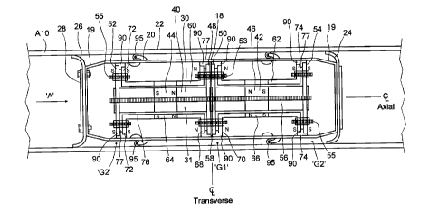
Pig 20 has, mounted within shell 22, a magnetic field generator 30 that
includes an
assembly of magnetic circuit elements 31, and sensing elements 32. Either pig
20 or trailer 21
may have signal processing and data recording elements 34, and at least one
power supply
element 36, and it may also have a location signal transmitter 38. Magnetic
circuit elements 31
may include elements of two primary magnetic circuits 40, 42 that each include
a magnet 44, 46
CA 02757488 2011-11-14
-13-
(which may be a cluster of stacked magnets), a first pole member or pole piece
48, 50 and a
second pole member or pole piece 52, 54. In one embodiment, the pole pieces
are circular discs
that extend in planes perpendicular to the long axis (i.e., the axial
direction) of pig 20. The pole
pieces are magnetizable materials of high magnetic permeability. Magnet 44,
first pole piece 48,
and second pole piece 52 are all joined in a continuous linking of highly
magnetically permeable
members. Similarly, magnet 46, first pole piece 50, and second pole piece 54
are all joined in a
continuous linking of highly magnetically permeable members. For ease of
description, the first
pole pieces 48, 50 will arbitrarily be identified as "North", or N, poles, and
the second pole
pieces will be designated as "South" or S. It could as easily be the opposite.
It may be noted that
a retainer, which may be in the nature of a non magnetically participating
core piece in the
nature of a threaded rod 56 is passed co-axially between these two assemblies,
and magnetically
isolated from them. Inasmuch as the magnets are quite powerful, and their
North poles are
advanced closely together, there may be a significant tensile force in
threaded rod 56. Additional
magnetically and electrically isolated threaded fasteners may also be used as
indicated at 53
sandwiching the first or N poles 48, 50, 68 and 70 of the primary and
secondary magnetic
circuits, and at 55, clamping the second, or S poles of the primary and
secondary magnetic
circuits. A non-magnetically participating gap maintaining member, or spacer
58 may be
mounted between first pole pieces 48, 50. Spacer 58 may have the form of a
radially extending
disc, and have a slim through-thickness. In one embodiment, this distance may
be from a few
thousandths of an inch to perhaps as much as 1/4 " depending on the diameter
of the magnetic
poles and the strength of the fields. It may be desirable for the spacing
between the mutually
repulsive poles 48 and 50 to be as small as practicable. A spacer may not
necessarily be
required, given the very strong mutually repulsive forces between the opposed
north poles.
Magnets 44, 46 may be permanent magnets, and may be rare earth magnets. They
may establish
a magnetic flux density in their respective pole pieces that is at magnetic
saturation.
Magnet circuit elements 30 may also include elements of two secondary magnetic
circuits 60, 62 that each include a magnet 64, 66 (which, may be a cluster of
stacked magnets), a
first pole member or pole piece 68, 70 and a second pole member or pole piece
72, 74. In one
embodiment, the pole pieces are annular discs that extend in planes
perpendicular to the long
axis (i.e., the axial direction) of pig 20. As will be understood, the pole
pieces are magnetizable
materials of high magnetic permeability. Magnet 64, first pole piece 68, and
second pole piece
72 are all joined in a continuous linking of highly magnetically permeable
members. Similarly,
magnet 66, first pole piece 70, and second pole piece 74 are all joined in a
continuous linking of
highly magnetically permeable members. For ease of description, the first pole
pieces 68, 70 will
arbitrarily be identified as "North", or N, poles, and the second pole pieces
will be designated as
CA 02757488 2011-11-14
-14-
"South" or S. , provided that it is the same polarity as the neighbouring pole
piece 48, 50, of the
primary magnetic circuit.
Magnet 64 (or 66 as may be) may have an annular body that seats concentrically
about
magnet 44 (or 46 as may be), or it may be made up of a cluster of magnets
mounted
circumferentially about magnet 44 (or 46) in a common, magnetically permeable
path. The
magnets and other elements of the outer, secondary magnetic path do not
contact the magnet or
magnets or other elements of the inner, or primary magnetic path. The
repulsive forces involved
may be quite substantial. To the extent possible, first pole pieces 68 and 70
of the secondary
magnetic circuit are mounted closely adjacent to, but without touching, first
pole pieces 48, 50,
respectively, of the first magnetic circuit, and second pole pieces 72, 74 are
mounted
correspondingly tightly adjacent to second pole pieces 52, 54. The second pole
pieces need not
necessarily be mounted as closely adjacent to, but not touching, each other as
the first pole
pieces, although it may be convenient to do so. Non-magnetically participating
spacers, 76, 77
may be placed between the various neighbouring pole pieces of the primary and
secondary
circuits to isolate the respective primary and secondary elements and so to
prevent the circuits
from touching. These spacers may be as thin as a few thousandths of an inch
thick, and may not
strictly be necessary as the repulsive forces between the members may tend to
be quite strong
and may tend to maintain a spacing between them of their own accord.
The magnetic flux density at the outer periphery of the pole pieces may tend
to be at
saturation. The strength of the magnetic field in the secondary circuit may
tend to be of a similar
order of magnitude to that in the first field, and may, in one embodiment, be
of substantially
equal strength. The outer diameter of the pole pieces of the secondary circuit
may be
approximately substantially similar to, or perhaps slightly less than the
outer diameter of the pole
pieces of the associated primary pole pieces. Inasmuch as the region in which
sensing may occur
is at or near the radial plane between the two primary circuit North pole
pieces, it may be that the
apparatus described may be relatively more sensitive to maintaining this
relationship as the
opposed pole pieces forced closely together (the North poles, as illustrated)
than at the more
distant, spaced apart poles, (the South poles, as illustrated).
Mounted between the two opposed North pole pieces is a first sensor array 80.
Sensor
array 80 may include a plurality of sensing members spaced circumferentially
about the outside
of an array carrier, which is, itself, mounted between the two adjacent
primary North poles. To
that end, spacer 58, may extend to pole pieces 48, 50, and may be the carrier
for sensor array 80.
Spacer 58 may be, or may include, a PC board with conductivity vial and layers
by which
CA 02757488 2011-11-14
-15-
signals from the sensors may be transmitted to and from a suitable data
collection bus, and to
such recording and data equipment as may be appropriate. Sensor array 80 may
include as many
as, for example, 250 sensors spaced circumferentially about the radially
outermost extremity
(i.e., the periphery) of the sensor carrier, e.g., spacer 58. This may tend to
give a relatively fine
degree of sectoral differentiation between observed readings, and a
corresponding level of
resolution of magnetic flux variation (or, by proxy, eddy current field
divergence) as a function
of circumferential location. The pitch spacing of the sectors of sensors 82 is
symbolised by 082.
While it is possible for the pitch spacing to vary, it may be arithmetically
convenient for the
pitch spacing of the sectors to be equal. In one embodiment each sensor 82 may
have the form
of Hall effect or GMR sensors (where no change in polarity is expected), with
the plane of the
face of the sensor lying tangentially, and radially outwardly of, the outer
periphery of the pole
pieces. Each sensor may be as little as about 2 mm, or somewhat less than
1/8", square. In one
embodiment these sensors may be axially offset in two alternating staggered
rows. These sensors
will tend to be used to measure magnetic flux density in the radial direction.
The sensing
apparatus may also include a second set or array 86 of sensors 88 each having
sensitivity to
changes in flux through their face, but little sensitivity to changes in flux
through their sides,
such as Hall effect sensors, which can sense a change in field polarity. The
"sensitive face" may
tend to lie in a radially extending plane, such that a normal to the plane of
the sensor face may
tend to extend in the axial direction. The number of sensors of array 86
spaced about the
circumference of the first pole pieces may be quite large, and may be in the
hundreds, and may
be the same in number as the number of radial axis flux sensors in array 80.
Sensors 88 may lie
in a plane axially to one side of sensing array 80. The sensing apparatus may
further include a
third set or array 92 of sensors 94, in which the number of sensors may tend
to be the same as
that of array 86, and which may tend to include Hall effect sensors similar to
sensors 88, which
lie in radial planes and have normal vectors in the axial direction. Array 92
may be axially offset
from array 86 to the other side of the plane of array 80. The various sensors
are connected to
signal processing apparatus 34 that samples and measures current in the
various sensors, and
then processes those values to yield interpretive results from the sampling
and measuring
process. Alternatively, or additionally, the data may be recorded for
subsequent post processing.
If field generator 30 and sensor array 80 may be mounted within shell 22 in a
manner that
interposes shell 22 between sensor array 80 (and field generator 30) and thus
both protects the
sensors and imposes a standoff between the sensors and the pipewall. Shell 22
may have
brackets or other fittings, indicated generically as 90 such as may tend to
maintain a spacing, or
center, field generator 30 and sensor array 80 within shell 22. In one
embodiment, pig 20 may
have sprung rollers, or runners 95, such as may tend to encourage pig 20 to be
maintained in a
generally centered position within pipeline A10.
CA 02757488 2011-11-14
16-
As may be noted, pig 20, when standing alone, will tend to "leak" magnetic
flux from the
North poles to the South poles. The arrangement of magnets is such that, at
rest, there may tend
to be a very high radial flux density in, and immediately adjacent to the
central plane between
pole pieces 48, 50, which may be the mid-plane of spacer 58. The secondary
magnetic field may
tend to provide a magnetic impedance between the North and South poles so that
the primary
magnetic field may tend to be urged or forced to divert to take a longer path,
such as may tend to
cause the primary field to flow preferentially into the adjacent pipe wall
rather more than might
otherwise be the case.
When pig 20 is introduced into a pipeline, and assuming the pipe wall to be of
a
ferromagnetic material such as a mild steel, the magnetic flux that leaks will
not be leaking into
an infinite air gap, but rather into a relatively small air gap 'G2', then
into a highly magnetically
permeable cylindrical wall, then back across another relatively small air gap
back into the far end
poles, thus completing the magnetic circuit. The magnetic flux leaking from
the central plane is
intended to be sufficient to saturate the surrounding cylindrical pipe wall.
Where the pressure differential across pig 20 is substantially constant, and
the pumping
system can maintain that constant pressure differential, pig 20 may tend to
move at
approximately constant speed down the pipe. Even if the speed is not precisely
constant, the
distance counter wheel, and the recording anomalies each time a flanged pipe
coupling is passed
will provide a record of the progress, and hence the location of pig 20.
Inasmuch as the pipe is
electrically conductive, and inasmuch as the motion of a magnetic field
relative to a conductive
loop will tend to cause a current in that loop, motion of the pig along the
pipeline will tend to
generate electrical currents in the adjacent pipe wall, those currents tending
to run perpendicular
to the direction of motion of the magnetic field. The electrical loop currents
in the pipe wall may
tend, in turn, to generate an associated magnetic field, or back EMF, tending
to oppose the
motion of the pig along the pipe. To the extent that the magnetic fields of
the (permanent)
magnets of the pig and the back-EMF field generated in the pipe wall are
additive, the overall
magnetic flux will appear to be tilted, or slanted in the radial and
rearwardly axial direction.
Sensors 88, 82 and 94 are of a type appropriate for sensing static magnetic
fields. These will
typically be Hall sensors or possibly GMR sensors where no change in polarity
is expected.
Sensor 82 measures the radial field strength. Sensors 88 and 94 measure the
field divergence. In
a stopped condition 88 and 94 will read approximately the same field strength.
Assuming that the
pipe wall is perfectly round, and the pig is perfectly centered, and the pipe
has no defects, the
flux sensed at each of sensors 82 will be equal, and the flux sensed in each
of sensors 88 will be
CA 02757488 2011-11-14
- 17-
equal, and the flux sensed in each of sensors 94 will be equal. However, when
pig 20 moves
along the pipe, the flux sensed in each sensor 88 will tend to be greater than
the flux sensed in its
associated sensor 94, because the magnetic flux field will be axially "tilted"
due to the back
EMF. The degree of that tilt will depend on the speed at which pig 20 moves
along the pipeline.
As the tool starts to move the field will drag away from the direction of
travel. In the case of
Figure 2a if the tool, (i.e., the sensing apparatus, pig 20), moves left the
field from the pole
pieces will drag right. This will cause 94 to read a higher field strength
than 92, and in an
opposite direction. In this way the degree of field drag can be measured.
Other arrangements of magnetic field sensors could be employed. For example,
in the
embodiment of Figure 3c, two arrays of sensors are indicated as 96 and 98.
These sensors are
distributed circumferentially about the periphery of spacer 58, much as above.
However, they are
inclined in the axial direction, (i.e., are angled with respect to the radial
plane of spacer 58) such
that each sensing loop provides a closed path that encircles both a radial
flux region, and an axial
flux region. Although the loops need not be spaced on equal circumferential
pitches, and
although the loops could be individually angled, it is convenient that the
arrays be on constant
pitches and that the angles of sensors 96 be equal and opposite to the angles
of sensors 98. That
is, sensors 96 are angled at +phi, and sensors 98 are angled at -phi. The
angle phi may be 45
degrees. However, to the extent that sensitivity in the axial direction may
need to be rather
higher than in the radial direction, and the mean axial and radial flux
components may be taken
in proportion as the inverse tan of the angle of inclination, phi may be a
relatively small angle, in
some embodiments less than 20 degrees. Alternatively, each sensor may include
several turns in
its windings, and it may have separate windings for measuring radial and axial
flux, or it may
have an intermediate tap at less than the total number of turns of the coil
for one or the other.
In the alternate embodiment of Figure 3d, spacer 58 may be supplanted by a
spacer,
sensor carrier or sensor mounting member (or members) 100, sandwiched between
opposed
primary pole pieces 48, 50 of the magnetic flux field generator. Member 100
may have a
peripheral flange, or widened radially outermost portion (or portions) 102
such as may support a
plurality of axially distributed flux sensors 104. There may be as few as two
such flux sensors,
one mounted to one side of the transverse centerline, and one mounted to the
other side.
Alternatively, there may be three such sensors, being a central sensor with
left and right hand (or
upstream and downstream) neighbours. The size and spacing of the sensors may
be such as to
extend axially beyond the respective upstream and downstream faces 106, 108 of
poles 48, 50,
such as to stand axially proud thereof, or to straddle the pole, and may stand
radially outward (or
radially proud) of the peripheral extremities of poles 48 and 50, by some
radial stand off
CA 02757488 2011-11-14
- 18-
distance. In this manner, when the B field drags, there may be a differential
flux observed across
sensors 104. E.g., the most axially upstream and downstream sensors 110 and
sensor 112 may
give different readings according to the extent to which the field is tilted
or skewed in the
direction of drag. Of course, a pig may have both axially spaced sensors lying
on a
circumferential face, or orientation, as items 104 of Figure 3d, and sensors
lying in a radial
plane, such as sensors 88 and 94 of Figure 3b, angled as in items 96 and 98 of
Figure 3c, or may
approximate an arc, as in items 114 of Figure 3e.
In this system, it may be understood that the largest magnetic resistance is
in the
generally annular air gaps between the pole pieces and the pipe wall. Since
the pipe wall is at
saturation, and the pipe wall is several orders of magnitude more magnetically
permeable than
the air gap, first, the amount of magnetic flux returning across the far end
air gaps must be equal
to the flux moving across the air gap at the central plane, and, second, a
defect in the pipe wall at
the far end gaps will tend not to cause a significant (or possibly sensible)
variation in the values
measured at the sensing arrays at the mid plane. The sensors may tend to be
much more highly
sensitive to variations in the field very locally in the region of the central
plane of the opposed
North poles.
To the extent that the overall magnetic flux is constant when the entire
circumferential
sum is taken, the flux sensed at each of sensors 82 will be a measure of the
resistance of the air
gap at that point. Thus, even if pig 20 is not centered, the size of the local
air gap can be
determined (and, indeed, plotted). Since the roundness (or other shape) of the
pole pieces is (a)
known; and (b) tightly controlled, this calculation may tend to reveal the
extent to which the pig
is running eccentrically, and whether the pipe is round. Lack of ovality may
be determined, and
where the lack of ovality is local, the presence of a dent or bulge may be
identified.
The flux in sensors 86 and 90 may tend to be sensitive to the extent that the
magnetic flux
"leans over", i.e., is angled axially out of the radial plane. If there are
local variations in the "tilt"
as a function of angular position in the circumferential direction, this is an
indication of the
existence of a local non-homogeneity, or defect. Where there is an axially
extending crack in the
pipe wall, the electrical circumferential eddy current in the pipe wall will
have to work around
the crack, lessening the back EMF. Where there is a circumferentially
extending crack, or
corrosion patch, and the pipe wall is at magnetic saturation, a portion of the
magnetic flux may
tend to have to flow elsewhere, leading to a reduction in the flux flowing to
that portion of the
pipe wall, and the "tilt" of the sensed EMF field may momentarily waver, or
stick, and then
appear to jump the gap or crack. Where there is corrosion and scale, and
pitting, the magnetic
CA 02757488 2011-11-14
- 19-
flux will jump intermittently as it finds and then loses high permeability
paths, leading to a
rapidly fluctuating signal strength in the various sensor elements.
Although pig 20 and the various pole pieces have been described as being round
when
viewed in the axial direction, this need not be so. It may be that they could
be square, or
rectangular, or hexagonal, or star shaped, or some other arbitrary shape,
subject to having the
signal processing ability to back out from the sensed results both the shape
of the pipe wall and
anomalies that may be observed. In general, where measurements are to be taken
from a
substantially round cylindrical object, a substantially round apparatus with a
relatively small
average gap size may tend to be relatively convenient to construct, and
relatively easy to analyse
in terms of mathematical manipulation of the resultant data to yield insights
into the condition of
the pipe wall. That is, the extraction of information from raw data may be on
the basis of
variation from a datum value. The datum value need not be zero, and the datum
value at one
sensor need not be the same as the datum value at another sensor. The sum of
values in the flux
in the radial direction may give an overall measurement of the resistance of
the magnetic path.
The sectoral (i.e., circumferential or peripheral) spacing of the sensors
permits sectoral variation
in the field to be measured, both with respect to sectoral datum values and
with respect to the
values, and variation, of adjacent sectors recorded at the individual sensors.
Pig 20 may be
ballasted to provide a means for maintaining itself in a generally known,
(e.g., upright)
orientation.
In the alternate embodiment of Figure 2b there may be a pig 120 that is
substantially the
same as pig 20 in construction and principles of operation, but differs
therefrom in being formed
as an annulus such as to permit flow of a production fluid through a central
passage 122 formed
within pig shell 124. There is sufficient flow resistance that pig 120 may
still be urged along
pipeline A20 by the production flow. Pig 120 may have a flow resistance
governor in the nature
of a movable vane or valve, indicated as 126, such as may permit longitudinal
speed of the pig to
be varied, e.g., as when placed in a gas flow line.
In the further alternate embodiment of Figure 2c, pig 130 is substantially the
same as pig
20, but rather than having two opposed primary poles in the nature of 48, 50,
pig 130 has a single
central primary magnetic circuit pole 132 (which for convenience is designated
`N'). Pole 132 is
sandwiched between the poles 68, 70 of like-polarity of the pair of adjacent
secondary magnetic
circuits 60, 62 all of poles 132, 68, and 70 being mutually repulsive. Again,
the secondary
magnetic circuits may tend to urge the radially outwardly oriented field of
pole 132 to be more
tightly or narrowly focused.
CA 02757488 2011-11-14
-20-
The embodiment of Figure 2d is provided to indicate that the detection
apparatus need
not be limited to a single observing section. In Figure 2d a pig 134 may be
taken as being the
same as pig 20, but instead of having a single magnetic field generator and
sensing section,
includes two field generator and sensing sections, as at 136 and 138 (their
polarities being
opposite), should additional readings or greater resolution be desired. In
general, such a pig may
have two, three, four or more such sections, as may be.
The embodiment of Figure 4, shows an anomaly detection apparatus 140 that is,
in
essence, pig 20 turned inside-out. That is, rather than having the body to be
surveyed
surrounding the observation apparatus, (as in the manner that pipe A10
surrounds pig 20 during
operation), apparatus 140 has an annular body 142 that surrounds the object to
be observed,
A140 which may be pipe of a drill string. Body 142 has an enclosing shell 144
in which there is
a field generator 146, and a sensing array 148. Motive power is provided by
the drill rig raising
and lowering the drill pipe. A computational complication is added if the
drill pipe is spinning
(i.e., rotating about its longitudinal axis) as it is being drawn past
apparatus 140. Apparatus 140
may be used where the internal configuration may tend to be impractical.
Applications such as
oil well drill pipe or oil well coiled tubing inspection are two
possibilities. In this case, as
contrasted to pig 20, the magnetic field is focused radially inward instead of
outward. While this
system is primarily designed for use in pipes, it is possible to use the
external system (e.g., of
Figure 4) for solid rods but the ability to detect defects in the center of a
thick rod may tend to be
limited.
In the further alternate embodiment of Figure 5, there is an anomaly detector
160 that
neither fully surrounds, nor is fully surrounded by, the object to be
examined, A160. Detector
160 is substantially similar to pig 20, but differs in effect, by having an
open-sided inspection
profile. In this instance, object A160 may be a rail of a rail road track. It
may be that the majority
of defects of interest may lie relatively close to the surface in the upper
region A162 of the head
A164 of the rail, where pitting, cracking, spalling, and internal defects may
most commonly
occur. In this instance the North and South pole pieces may be plates, such as
North pole plate
164 contained within housing 166. The inner face of plate 164 may have a
profile conforming
generally to the shape of an unworn rail, as at 168, and the inside face of
the profile (and hence
the sensing array), may be protected by a non-electro-magnetically
participating shell 170 that
may include, or have mounted to it, a sliding wear member 172 (also electro-
magnetically non-
participating). In this case the axial motive power is provided by a vehicle
that is driven along
the rails, and that tows or otherwise propels sensing apparatus 160 forward.
The towing device
CA 02757488 2011-11-14
-21-
may lift apparatus 160 when it encounters switches or diamonds. An array of
sensors 174 is
mounted about the portion of the profiled periphery of interest. The axial
spacing of poles of
primary and secondary magnetic circuits may be relatively small, and may be of
similar
magnitude to that of the spacing between primary poles 48 and 50.
The pipeline inspection apparatus, i.e., pig 20 or pig 120 may be employed to
seek
information permitting the measurement, or estimation, of internal and
external corrosion, axial
and circumferential cracks, and the magnitude of ovality and denting, if any.
The embodiments
of defect detectors described herein may tend to permit pipe wall examination
or sensing,
without the field generator or the sensors having to touch, let alone ride
against, the pipe wall.
That is, shell 22 (or 122) may tend to permit the sensors to be protected, and
sealed from the
production (or other) fluids.
The field generator (i.e., the magnetic circuit elements) of this inspection
apparatus may
tend to emit a relatively strong and mostly parallel, disc shaped magnetic
field. The plane of the
disc is perpendicular to the pipeline axis such that the emitted field is
predominantly normal to
the surface of the wall of the adjacent object to be inspected. Each of the
three defect types,
cracks, corrosion and dents, are measured using different effects of the
magnetic field generator.
Cracks in the pipe wall are measured using eddy currents. In this case the
eddy current is
generated in the pipe wall when the field generator is in motion. The
generated eddy currents
move circumferentially in the pipe wall and are perpendicular to the
longitudinal axis ofthe pipe.
The magnitude of the eddy current is determined by the local magnetic field
strength and the
velocity of the field generator. Note that the velocity is a function of both
the axial velocity and
the rate of rotation of the field generator. Normally the rate of rotation may
tend to be very small,
and as such maybe ignored. Figures Id and 1e show a schematic or conceptual
representation of
the eddy current flow in a portion of a plate or shell in the region of an
anomaly, A25. Well
away from anomaly A25, the eddy current field is substantially uniform or
regular, and the
associated back-EMF field associated with those eddy currents is regular and
relatively even or
uniform. When the eddy current field encounters a crack, such as anomaly A25
with a
longitudinal component, the eddy current field is forced to deviate around the
crack. As
illustrated in the figures, the eddy current deviates both around and below
the crack defect. This
has the effect of generating a localized change in the eddy current density,
and hence a local
change in the back-EMF associated with the eddy current field that is abnormal
as compared to
the field that would be observed generally elsewhere. As the field generator
moves along the
pipe, it omits a moving wave-front, pulse, of magnetic flux. The magnetic flux
passed into the
CA 02757488 2011-11-14
-22-
pipewall as the wave passes causes eddy currents in the wall. The magnitude of
the eddy
currents, and their direction is proportional to the time rate of change of
the imposed magnetic
field. These eddy currents in turn generate a magnetic field that opposes the
field generator's
magnetic field, i.e., a back EMF. To the extent that the leading edge of the
eddy current may tend
to yield a back EMF that is opposite in direction to the trailing edge eddy
current, the sensed
magnetic field may appear to be tilted. The net result is that the magnetic
field from the field
generator appears to "drag", i.e., appears to lag behind at an angle. The
degree of drag is
dependent on the local eddy field strength. As the local eddy current density
increases or
decreases the field drag increases or decreases. By measuring the degree of
field drag, and
combining that information with corrosion data, the degree of cracking can be
determined.
Ovality and corrosion may tend to be determined by measuring the local radial
strength
of the magnetic field emitted by the field generator. Figure lb shows a cross
sectional view of
the magnetic field distortions that may occur for the various defects. Inward
dents may cause a
local increase in field density (since there is an apparent local reduction in
resistance of the air
gap), with a local decrease in field density at the edges. Corrosion may tend
to manifest with the
opposite effect. Internal corrosion may typically show a steeper field
gradient than external
corrosion. It may be noted that as the axial velocity of the field generator
increases the ability to
detect external cracks and corrosion may tend to degrade. In general the
velocities have to be
fairly high for this to happen, and may occur at velocities that may be
greater than 10 m/s (36
km/h).
The field generator 30 of pig 20, for example, has a pair of closely spaced
magnets whose
poles oppose each other, as in the manner of pole pieces 48, 50. In this case
the North poles are
facing each other. This may tend to produce a locally strong magnetic field
that is concentrated
radially around the longitudinal axis (i.e., is concentrated in a radial disc
extending away from
the longitudinal axis). In a pipeline pig application the gas (e.g., air,
natural gas etc.,), liquid or
quasi-liquid fluid (e.g. oil, water, or slurry) in the gap between (a) the
outer circumferential
edges of the primary field generator pole pieces and (b) the pipe wall, acts
as a resistance to the
magnetic field. As the size of the gas or fluid gap increases, a higher
percentage of the magnetic
flux of the primary field may tend to travel directly from pole-to-pole in the
gas or liquid gap.
The secondary field generator creates a blocking field that may tend to force
or urge the
magnetic flux or the primary field to move into the pipe wall. The effect is
to tend to make the
magnetic lines of force at the center of the field generator move parallel in
the radial direction
into the pipe wall. It may also tend to enhance the ability of the magnetic
field to be affected by
defects on the far side of the pipe. The physical dimensions of the field
generator are dependent
CA 02757488 2011-11-14
-23-
on the pipe diameter, bend radius, and restriction clearance requirements. The
spacing (i.e.,
isolation or segregation) of the primary field generator from the secondary
field generator is
described above.
Inasmuch as the field generator and sensor assembly is contained within shell
22 (or 122
or as may be), unlike existing intelligent pigs, they do not need to be in
contact with the pipewall
for sampling to occur, and so may tend not to be affected by debris; weld
heads, or other deposits
in the pipeline.
There is no specific requirement that the field generator be round, oval and
rectangular
shapes are also possible. However, these configurations of irregular geometry
may tend to
require special post processing compensations to correct for the basic
irregular field strengths
that are generated.
Various embodiments have been described in detail. Since changes in and or
additions to
the above-described examples may be made without departing from the nature,
spirit or scope of the
invention, the invention is not to be limited to those details.