Note: Descriptions are shown in the official language in which they were submitted.
- 1 -
ATTACHMENT MECHANISM
FIELD OF THE INVENTION
This invention relates to armor elements, in particular, add-one armor
elements.
BACKGROUND OF THE INVENTION
Armor elements are commonly used to protect a body against various threats,
mostly
incoming projectiles. Such armor elements are adapted to dissipate and/or
absorb the kinetic
energy of the incoming projectile in order to prevent it from penetrating the
body.
When it is desired to protect a body, for example, a vehicle, armor elements
are
usually mounted onto the exterior/interior of the vehicle and are fastened to
become affixed
thereto.
Mounting of an armor element onto a vehicle is normally performed either by
welding the armor element onto the hull of the vehicle at a location thereon
in which
protection is sought or by bolting, where the armor element and the hull of
the vehicle are
pre-formed with corresponding bores/threads for receiving therein bolts/screws
to attach the
armor element to the hull.
In the former case, the armor element is affixed to the hull permanently,
whilst in the
latter case the armor element is detachably attached to the hull and can serve
as an add-on
panel.
SUMMARY OF THE INVENTION
According to one aspect of the subject matter of the present application there
is
provided an attachment mechanism adapted for attachment of an armor element to
a body to
be protected by said armor element, said attachment mechanism having a central
axis and
CA 2757704 2019-02-08
- 2 -
comprising a first unit and a second unit which are adapted to engage with
each other to
provide said attachment, said first unit comprising a first static member and
said second unit
comprising a second static member and a working member, one of which static
members is
adapted for fixed attachment to said armor element, and the other is adapted
for fixed
attachment to said body to be protected; wherein said second unit being
configured for
assuming a first, disengaged position, in which said working member is
disengaged from
said first unit such that said armor element and said body to be protected are
detached from
one another and a second, engaged position in which a first engagement of said
working
member with said first unit is provided such that said armor element and said
body to be
protected are fixedly attached to one another, and wherein said working member
further
comprises a locking member configured for a second engagement with said first
unit to
prevent disengagement of said working member from said first unit, thereby
retaining said
first unit and said second unit fixedly attached to one another at said
second, engaged
position, wherein said first unit further comprises a dynamic member,
configured for being
dynamically displaceable with respect to said first static member, and wherein
said first
static member is configured for engagement with said locking member, whilst
said dynamic
member is configured for engagement with the working member of the second
unit.
The first unit can have an affixing portion for attachment thereof to one of
the armor
element and body to be protected, and a mounting portion for attachment
thereto of the
second unit, in said engaged position, the locking member being configured for
engagement
with said mounting portion.
Said locking member can be configured for assuming a first, unlocked position,
in
which it is disengaged from said mounting portion of the first unit, so that
said working
member is free to disengage from said first unit, and a second, locked
position, in which said
working member is prevented from disengaging from said first unit. The second
unit can
further comprise a biasing arrangement configured for urging said locking
member into said
second, locked position.
CA 2757704 2020-01-06
- 2a -
The mounting portion of the first unit can have a first engagement section
configured
for engagement with said working member and a first locking section configured
for
engagement with said locking member, and said locking member can be formed
with a
second locking section configured to engage the first locking section at least
in said locked
position.
The first unit can have a longitudinal axis and said first locking section is
disposed at
a distance from the affixing portion which is greater than that of the first
engagement
section.
The first locking section of the first unit can be in the form of a locking
recess
configured for receiving at least a portion of the second locking section of
said locking
member, at least in said second, locked position.
CA 2757704 2020-01-06
CA 02757704 2011-11-14
- 3 -
In the unlocked position, the locking member is configured to assume a
plurality
of different orientations with respect to the working member, whilst in the
locked
position it can assume only a single orientation which is different of any one
of said
plurality of orientations. The design can be such that in said locked
position, said single
orientation is visually distinguishable from any one of said plurality of
different
orientations of the unlocked position.
For example, said working member can be formed with a first indication surface
and said locking member can be formed with a second indication surface,
wherein in
said locked position, the first indication surface and the second indication
surface are
aligned to create a visual indication that the locking member is in said
second locked
position.
According to one example, in said locked position, said first indication
surface
and said second indication surface are aligned to be flush with one another.
According
to another example, each of said first indication surface and said second
indication
surface have an imprint thereon, so that in said locked position, said first
indication
surface and said second indication surface are aligned so as to form a
combined
indicative image/pattern.
In addition, said locking member can assume said single orientation only when
said working member is properly engaged with said first unit (i.e. when said
second unit
is in said first, engaged position).
One advantage which can arise from the above design, is that an operator
mounting and attaching the armor element to said body to be protected using
the
attachment mechanism can easily identify if the locking member is not in said
locked
position, thereby alerting him to the fact that the attachment mechanism is
not properly
engaged and locked.
The locking member can be designed so that displacement thereof from said
locked position into said unlocked position is configured for manual
operation, so that it
is prevented from spontaneous displacement between the two positions. In
addition, the
design is such that said locking member is externally accessible for an
operator.
According to a particular example, the locking member can be configured for
being
grasped by said operator and manually displaced between said locked position
and said
CA 02757704 2011-11-14
- 4 -
unlocked position. Furthermore, the locking member, once displaced into the
unlocked
position may be used as a handle facilitating revolving of the working member.
Said first unit can comprise, in addition to said static member, a dynamic
member, wherein said static member is configured for fixed attachment to
either of said
armor element and body to be protected, and said dynamic member is configured
for
being dynamically displaceable with respect to said first static member.
According to a specific example, said first static member can be configured
for
engagement with said locking member, whilst said dynamic member can be
configured
for engagement with the working member of the second unit.
According to another aspect of the subject matter of the present application,
there is provided an attachment mechanism adapted for attachment of an armor
element
to a body to be protected by said armor element, said attachment mechanism
comprising
a first unit and a second unit which are adapted to engage with each other to
provide
said attachment, said first unit comprising a first static member and a
dynamic member,
and said second unit comprising a second static member and a working member,
one of
which static members is adapted for fixed attachment to said armor element,
and the
other is adapted for fixed attachment to said body to be protected, said
working member
being configured for engagement with said dynamic member and assuming a first,
disengaged position, in which it is disengaged from said dynamic member such
that said
armor element and said body to be protected are detached from one another and
a
second, engaged position in which said working member is engaged with said
dynamic
member such that said armor element and said body to be protected are fixedly
attached
to one another, and wherein said first unit further comprises a biasing
arrangement
urging said dynamic unit towards said first static member.
According to a particular design, the first static member can be associated
with
an affixing portion of the first unit, configured for attachment thereof to
one of the
armor element and body to be protected, and the dynamic member can be
associated
with a mounting portion of the first unit, configured for attachment thereto
of the second
unit, in said engaged position. The design can be such that in said engaged
position,
when the armor element is affixed to the body to be protected, the affixing
portion is
more axially remote from said second unit than said mounting portion.
Thus, in said engaged position, due to the biasing of the dynamic member, the
latter is configured for applying a force to at least a portion of the working
member of
CA 02757704 2011-11-14
- 5 -
the second unit, urging it towards the affixing portion of said first unit,
thereby
facilitating the engagement between the first and the second unit.
In addition, the biasing arrangement is configured to provide the dynamic
member with a displacement range, thereby allowing the attachment mechanism to
compensate for tolerance errors occurring in the manufacturing of the first
and of the
second unit.
The dynamic member can be configured for assuming a first biased position
which corresponds to the position of the dynamic member when the first unit is
disengaged from said second unit (i.e. the second unit's disengaged position),
and a
second biased position which corresponds to the position of the dynamic member
when
the first unit is engaged with said second unit (i.e. the second unit's
engaged position).
The dynamic member can be formed with at least one restriction element and
said first static member can be formed with a restriction space having a first
abutting
end, configured for abutting the restriction element of said dynamic member
when it
reaches its first biased position and a second abutting end configured for
abutting the
restriction element of said dynamic member when it reaches its second biased
position.
The dynamic member can be configured for performing an axial movement with
respect to the first static member, so that in said first biased position, it
is located at a
first axial distance (D1) from said affixing portion, and in said second
biased position it
is located at a second axial distance (D2) from said affixing portion, greater
than said
first axial position. D2> D1
According to a specific example, the dynamic member can be configured for
assuming an additional, intermediate position between said first axial
position and said
second axial position, in which the axial distance between the dynamic member
and the
affixing portion of the first unit (DM) is greater than the distance Di and
smaller than the
distance 1)2, i.e. D2 >DN4 > Di.
The dynamic member can be configured for assuming said intermediate axial
position at least at one point during displacement of the working member
between said
engaged position and said disengaged position.
According to a particular example, one of said dynamic member and said
working member can be formed with guide paths, and the other can be formed
with
guide projections configured for being received within said guide paths in
order to
CA 02757704 2011-11-14
- 6 -
define a trajectory along which said working member is configured to progress
during
its displacement between said disengaged position and said engaged position.
In addition, said guide paths biased can be formed with a first segment
configured for coming in contact with the guide projections during
displacement of the
working member between the disengaged position into the engaged position, and
a
second segment configured for coming in contact with the guide projections
when the
working member is in said engaged position.
According to a particular example, the dynamic member can be formed with
said guide projections and said working member can be formed with said guide
paths.
In addition, the dynamic member comprise a pin element having a guide portion
configured for constituting at least one of said guide projections, and a
restriction
portion configured for constituting said at least one guide element.
The arrangement can be such that due to the biasing arrangement, the movement
of the dynamic member is biased such that the guide projections are constantly
urged
towards the armor/body to which the first unit is affixed, to thereby, during
engagement
with the working member, apply a force on the working member so as to urge it,
and
consequently the entire second unit, towards said first second unit.
In mounting, bringing said working member from said disengaged position into
said engaged position can be performed by displacement of the working member
along
said trajectory by a single movement.
According to a first example, the biasing arrangement can have a first end
configured for engaging said dynamic member at a first location, and a second
end
configured for engaging said first static member at a second location which is
more
remote from the affixing portion than said first location. Alternatively,
according to a
second example, said first location may be more remote from the affixing
portion than
said second location.
With reference to the above, in the first example the biasing arrangement can
be
a compression spring while in the second example the biasing arrangement can
be a
tension spring.
Both the first unit and the second unit the attachment mechanism can be
manufactured from materials having ballistic resistance properties, so that
when said
armor element is mounted onto said body to be protected, the area in which the
first unit
CA 02757704 2011-11-14
-7..
and second unit are located maintains ballistic properties similar to those of
the armor
element.
According to a particular example, either or both of said first unit and
second
unit are configured for fixed attached to the armor element and body to be
protected by
insertion of the formers into respective holes/cavities of the armor element
and body to
be protected. Thus, due to the ballistic nature of the materials from which
the
attachment mechanism is manufactured, the above holes/cavities to no
deteriorate the
ballistic resistance of the armor element and body to be protected.
The attachment mechanism can be manufactured out of a hard material which
hardness ranges between 30 to 80 Rockwell C, more particularly between 40 to
70
Rockwell C, and even more particularly between 50 to 60 Rockwell C. One
example of
such a material can be tempered 4130 steel.
BRIEF DESCRIPTION OF THE DRAWINGS
In order to understand the invention and to see how it may be carried out in
practice, embodiments will now be described, by way of non-limiting example
only,
with reference to the accompanying drawings, in which:
Figs. IA to 1D are schematic isometric, front, rear and side views of an
attachment mechanism of the present application;
Fig. 2 is a schematic isometric exploded view of the attachment mechanism
shown in Figs. IA to ID;
Fig. 3A is a schematic isometric view of a first unit comprised in the
attachment
mechanism shown in Figs. IA to 1D;
Fig. 3B is a schematic isometric view of the first unit shown in Fig. 3A with
the
housing thereof being removed;
Figs. 3C and 3D are schematic section views of the first unit shown in Fig.
3A,
at different positions of a dynamic member of the first unit;
Figs. 4A and 4B are schematic isometric views of a second unit comprised in
the
attachment mechanism shown in Figs. IA to ID, at respective closed and open
positions;
Figs. 5A and 5B are schematic isometric, first side and second side views of
the
attachment mechanism shown in Figs. IA to ID, with the housing of the second
unit
being removed;
CA 02757704 2011-11-14
- 8 -
Figs. 6A and 6B are schematic isometric and front section view taken along a
plane A-A shown in Fig. 1B;
Fig. 7A is a schematic isometric view of an attachment mechanism according to
another example of the present application:
Fig. 7B is a schematic enlarged view of detail A shown in Fig. 7A;
Fig. 8A is a schematic isometric cross-sectional view of the attachment
mechanism shown in Fig. 7A; and
Fig. 8B is a schematic enlarged view of detail B shown in Fig. 8A.
DETAILED DESCRIPTION OF EMBODIMENTS
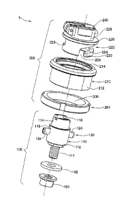
With reference to Figs. IA to 2, there is shown an attachment mechanism
generally designated 1, configured for attachment of an armor element A (shown
Fig.
1C) to a body to be protected B (shown Fig. 1C). The attachment mechanism 1
comprises a first unit 100 and a second unit 200 configured for mutual
engagement with
one another. The first unit 100 is configured for fixed attachment to the body
B while
the second unit 200 is configured for fixed attachment to the armor element A.
However, it is appreciated that an opposite arrangement may be used (i.e.
first
unit 100 attached to the armor element A and the second unit 200 to the body
B), so
long as the units 100, 200 are configured for mutually engagement with one
another.
In Figs. IA to 1D, the attachment mechanism 1 is shown with the first unit 100
being engaged with the second unit 200, such that the armor element A is
fixedly
attached to the body to be protected, B.
With reference being drawn to Fig. 2, the attachment mechanism has a central
axis X, and each of the first unit 100 and second unit 200 has a central axis,
so that
when the first unit 100 is engaged with the second unit 200, the central axes
of the units
100, 200 are aligned with one another and constitute the central axis X of the
attachment mechanism 1.
The first unit 100 comprises a first static member 110 configured for static
attachment to the body to be protected (i.e. without moving with respect
thereto) by a
nut 101 and washer 102. The first unit 100 further comprises a dynamic member
120
configured for displacement with respect to the first static member 110, and
for
engagement with the second unit 200.
- 9 -
The second unit 200 comprises a second static member 210 configured for static
attachment to the body to be protected (i.e. without moving with respect
thereto) by a nut
201. The second unit 200 further comprises a working member 220 configured for
displacement with respect to the second static member 210, and for engagement
with the
first unit 100.
The working member 220 also comprises a locking arrangement 240 configured for
preventing disengagement between the first unit 100 and the second unit 200,
when the two
units 100, 200 are engaged with one another.
The arrangement is such that when the first unit 100 and the second unit 200
are
mutually engaged, the working member 220 of the second unit 200 is configured
for a first
engagement with the dynamic member 120 of the first unit 100, and the locking
arrangement
240 is configured for a second engagement with the first static member 110 of
the first unit,
the first and the second engagements being spaced from each other along the
central axis X
as seen in Fig. 6A, and explained below in more detail with reference to Figs.
5A and 6A.
Turning now to Figs. 3A to 3D, the first unit 100 will now be described (shown
in
these figures without the nut 101 and washer 102). The first unit 100 is
constituted by an
affixing portion AP configured for fixed attachment of the first unit 100 to
the body B, and a
mounting portion MP configured for engagement with the second unit 200.
The affixing portion AP is in the form of a stud 111 having thereon a thread
configured for threading thereon the nut 101. The stud 111 has a length L
(shown Fig. 3D)
which is designed to he greater than the thickness of the body B, so that when
the stud 111 is
passed through a designated through-going hole of the hull of the body, it is
long enough to
project from the other side of the hull, allowing threading thereon the nut
101.
Observing the mounting portion MP, the first static member 110 comprises a
housing 112 having an inner cavity 113 (shown Figs. 3C and 3D), accommodating
therein
the dynamic member 120. The housing 112 has a first end 112a adjacent the
affixing portion
AP and a second end 112b more remote from the affixing portion AP.
The housing 112 is formed with two side openings 115 radially opposite from
one
another, configured for allowing a portion of the dynamic member 120 to
project therefrom.
The side openings 115 are axially prolonged so as to have a first abutting end
115a and a
CA 2757704 2019-02-08
- 10 -
second abutting end 115b, so that the second end 115b is axially closer to the
affixing
portion AP than the first end 115a.
In addition, the housing is formed, at the second end 112b with a tubular
projection
114 configured for engagement with the locking arrangement 240 of the second
unit 200.
Specifically, the projection 114 is formed with two extensions 116, radially
spaced apart
from one another to define a central recess 118 configured to receive a
portion of the locking
arrangement 240.
With particular attention being drawn to Fig. 3B, the dynamic member 120
comprises a main hub 122 having a tubular shape and being formed therein with
a central
channel 123 oriented transversely to the central axis X, and receiving therein
a securing pin
124. The length of the securing pin is such that it radially protrudes from
the main hub 122.
The securing pin 124 is also formed with a central slit 126 providing it with
required
flexibility in order to insert it into the channel 123 of the main hub 122.
In addition, the dynamic member 120 comprises a biasing arrangement 128
configured for constantly biasing the main hub (and consequently the securing
pin 124)
towards the affixing portion AP of the first unit 100. The biasing arrangement
128 is held in
place by a cover plate 127 and retained within the housing 112 by a pressure
ring 129
abutting the second end 112b of the housing 112.
Reverting now to Figs. 3A, 3C and 3D, the arrangement is such that when the
dynamic member 120 is accommodated within the housing 112, the securing pin
124
projects from the side openings 115 of the housing 112.
In addition, the diameter of the securing pin 124 is smaller than the axial
extension
of the side openings 115, providing the securing pin 124 with a certain degree
of freedom
defined by the displacement range delimited by the abutting ends 115a, 115b of
the side
openings 115.
Under the operation of the biasing arrangement 128 (e.g. a compression
spring), the
securing pin 124 is constantly urged towards the affixing portion AP, so that,
when the first
unit 100 is disengaged from the second unit 200, the securing pin 124 abuts
the second end
115b of the opening 115 (see Fig. 3C).
CA 2757704 2019-02-08
- 11 -
In operation, when the dynamic member 120 of the first unit 100 is engaged
with the
working member 220 of the second unit 200, the securing pin 124 can axially
displace
towards the first abutting end 115a, as shown in Fig. 3D. The securing pin 124
may thus
assume a first position in which it is at a distance D1 from the most axially
remote point of
the AP and a second position in which it is at a distance D2 from the most
axially remote
point of the AP, D2> DI. This displacement range allows the first unit 100 of
the attachment
mechanism 1 to compensate for any tolerance error occurring in the first unit
100 and
second unit 200.
In addition, when the dynamic member 120 is engaged with the working member
220, urging of the securing pin 124 towards the affixing portion AP by the
biasing
arrangement facilitates a stronger engagement between the working member 220
and the
dynamic member 120, as will be explained in detail with respect to Figs. 5A
and 5B.
It is understood that since the dynamic member 120 has a certain degree of
freedom,
it may assume different axial positions with respect to the housing 112, and
consequently,
the securing pin 124 may assume different positions with respect to the
abutting ends 115a,
115b of the side openings 115 of the housing.
Turning now to Figs. 4A to 5B, the second unit 200 will now be described in
detail.
The second unit 200 comprises a second static member 210, configured for fixed
attachment
of the second unit 100 to the armor element A, and a working member 220
configured for
the above first and second engagements with the first unit 100.
The second static member 210 is in the form of a tubular ring 212 having a
central
cavity 214 configured for receiving therein the working member 220. The outer
surface of
the ring 212 is threaded, allowing threading thereon the nut 201. Similar to
the first unit 100,
the axial length of the nut is designed to be greater than the thickness of
the armor element
A to which the second unit 200 is attached, so that when the ring 212 is
passed through a
designated through-going hole of the armor element A, it is long enough to
project from the
other side of the armor element, allowing threading thereon the nut 201.
The working member 220 is received within the central cavity 214 of the second
static member 210, and comprises a locking arrangement 240 articulated
thereto, which will
be discussed in detail with reference to Figs. 4A, 4B, 6A and 6B.
CA 2757704 2019-02-08
- ha-
The working member 220 has a central axis and a flange F axially separating
the
working member 220 into an internal portion IP configured for the above
mentioned first
engagement with the first unit 100, and an external portion EP configured to
be accessible
by an operator, at which the above mentioned second engagement with the first
unit 100
takes place.
In addition, the working member 220 is also prevented from disconnecting from
the
static member 210 via the flange F being received within a recess 218 formed
in an inner
surface of the static member 210, and delimited by a pressure ring 229.
CA 2757704 2019-02-08
CA 02757704 2011-11-14
- 12 -
Furthermore, when the second unit 200 is not in engagement with the first unit
100, the
working member 220 is configured for freely revolving within the static member
210.
Observing the internal portion IP, the working member is formed with a tubular
portion 222 having a central cavity C configured for receiving therein at last
a portion of
said first unit 100. The tubular portion 222 is further formed with two
channels 224
extending along the perimeter of the tubular body 222. The channels 224 are
through-
going with respect to the wall of a tubular body 222, so as to allow an
element received
within the central cavity C (in the present example the securing pin 124 of
the dynamic
member 120 of the first unit 100) to protrude through the channels 224 towards
the
outside of the tubular body 222.
Each channel 224 has a first end 224a located at an end of the tubular body
222
axially remote from the external portion EP and a second end 224b located at
an end of
the tubular body 222 closer to the external portion EP. The first end 224a is
formed
with an opening, allowing an element (in the present example the securing pin
124 of
the dynamic member 120 of the first unit 100) to be receive within the channel
224
during axial displacement of the working member 220.
In addition, each of the channels 224 is formed, at said second end 224b with
a
recess 226 having an axial extension towards the end of the tubular body 222
remote
from the external portion, configured for receiving therein a portion of the
securing pin
124 of the dynamic member 120 of the first unit 100.
Referring now also to Figs. 6A and 6B, during engagement of the first unit 100
and the second unit 200, the former is fixedly received within the body B so
that the
mounting portion MP thereof protrudes from the body B, and the latter is
fixedly
attached to the armor element A.
In assembly, the working member 220 of the second unit 200 is aligned so that
the openings formed at the first ends 224a of the channels 224 are angularly
aligned
with the portions of the securing pin 124 projecting from the housing 112 of
the first
unit.
Once aligned, the armor element A may be axially displaced with respect to the
body B, so that the projections of the securing pin 124 are received within
the channels
224 of the working member 220. Thereafter, the working member 220 is revolved
about
the central axis X of the second unit 200 (which is also the central axis X of
the
attachment mechanism and of the first unit 100 since they are all aligned when
- 13 -
engaged), in this case in a CW direction, so that the portions 223 of the
tubular body 222 of
the working member 220 slide in under the projections of the securing pin 124.
Revolution of the working member 220 continues until securing pin 124 abuts
the
second end 224b of the channels 224 of the working member 220. Once the
projecting
portions of the securing pin 124 have reached the second end 224b, and due to
the biasing
arrangement 128 urging the securing pin 124 towards the affixing portion AP,
the projecting
portions of the securing pin 124 slip into the recess 226 of the channels 224.
It is understood that since the surface of the recess 226 is more axially
remote from the
external portion EP that the surface of the portions 223, the portions In of
the securing pin
124 received within the recess 226 are prevented from sliding through the
channels 224, and
so the working member 220 is prevented from disengagement from the dynamic
member 120.
In addition, since the securing pin is biased by the biasing arrangement 128,
it
constantly applies a force T on the portions 223 of the working member 220,
thereby further
securing the engagement between the first unit 100 and the second unit 200.
With additional reference being made back to Figs. 4A and 4B, the external
portion
EP of the working member 220 is formed with a tubular projection 225 having
two extensions
227 radially opposite one another defining a central recess 228 configured for
receiving
therein the locking arrangement 240.
The locking arrangement 240 is located at the external portion EP of the
working
member 220 and is pivotally articulated to the extensions 227 of the working
member 220 via
a hinge 245.
The locking arrangement 240 comprises a locking latch 242 configured for
displacing
between an unlocked position shown in Fig. 4B and a locked position shown in
Fig. 4A. The
locking arrangement 240 also comprises a biasing spring 248 configured for
maintaining the
locking latch 242 in its locked position.
Reverting to Figs. 6A and 6B, when the working member 220 of the second unit
200
is fully engaged with the dynamic member 120 of the first unit 100 as
described above, the
locking latch 242 is configured to assume its locked position in which it is
received within the
recess 228 of the working member 220, and more importantly, within the recess
118 of the
static member 110 of the first unit 100.
CA 2757704 2018-05-01
- 14 -
In the locked position shown in Fig. 6B, since the locking latch 242 is
received within
the recess 118, which is in turn, formed in the static member 110 which is
prevented from
revolving (being fixedly attached to the body B), the working member 220 is
prevented from
revolving about its axis. Thus, as long as the locking latch 242 is in its
locked position, the
working member 220 is prevented from disengaging from the dynamic member 120
of the
first unit 100, thereby keeping the armor element A fixedly attached to the
body B.
It is noted that the locking latch 242 cannot assume its locked position, i.e.
it cannot be
received within the recess 118 of the static member 110 unless the working
member 220 has
completed its revolution about the axis and is properly engaged with the
securing pin 124 of
the dynamic member 120. In other words, so long as the recess 118 of the
static member is
not aligned with the recess 228 of the working member 220, the locking latch
242 will not be
able to assume it position.
It is also noted that in the locked position, an external surface S1 of the
locking latch
242 is nearly flush with an external surface S2 of the extensions 227 of the
working member
200. This orientation of the surfaces S1 and S2 is only possible at the locked
position of the
locking latch 242.
Thus, when mounting the armor element A onto the body to be protected B, an
operator perfolining the mounting can have a clear and visual indication
whether the armor
element A is properly attached to the body B or not. In other words, if, after
mounting, the
locking latch 242 is not in a position in which the surface S1 and S2 are
nearly flush with one
another, this should indicate that the working member 220 of the second unit
200 is not
properly engaged with the dynamic member 120 of the first unit 100.
In order to disengage the first unit 100 from the second unit 200 and detach
the armor
element A from the body B, it is first required to manually displace the
locking latch 242 into
its unlocked position (shown in Fig. 4B), and thereafter revolve the working
member 220
about its axis in a direction opposite to that used during engaging (in this
case CCW).
Manual displacement of the locking latch 242 can be performed by an operator
manually grasping and lifting the locking latch 242 until it reaches a
position in which no
portion of it is received within the recess 118 of the static member 110. In
this
CA 2757704 2018-05-01
CA 02757704 2011-11-14
- 15 -
position, the locking latch 242 may also be used as a handle facilitating the
revolving of
the working member 220.
It should be noted that since the projecting portions of the securing pin 124
are
received within the recess 226 and held there via the biasing arrangement 128
of the
dynamic member 120, it may be required to apply a certain amount of force in
order to
cause the projections to pop-out of the recess and to cause the working member
220 to
revolve about the axis.
In addition, during mounting of the armor element A onto the body B using the
attachment mechanism 1, the locking latch 242 may be required to be displaced
into its
unlocked position in order to allow revolution of the working member 220 with
respect
to the second static member 200 and the first unit 100.
At least the majority of the components of the attachment mechanism 1,
including the first static member 110, second static member 210, dynamic
member 120,
working member 220 and locking arrangement 240 can be made of materials having
a
high ballistic resistance. The ballistic resistance of the materials can be
chosen such that
it does not fall short of the ballistic resistance of the armor element A
attached to the
body B.
Such materials can have a hardness which ranges between 30 to 80 Rockwell C,
more particularly between 40 to 70 Rockwell C, and even more particularly
between 50
to 60 Rockwell C. One example of such a material can be tempered 4130 steel.
Turning now to Figs. 7A to 8B, another example of the attachment mechanism is
shown, generally designated as 1', and differing from the attachment mechanism
1 in
the construction of the locking latch 242' and in the securing pins 124' and
245'.
In particular, the locking latch 242' is slightly more robust than the latch
242
previously described, and is now formed with a shaped recess 246' which is
sized and
shaped to receive only the tip of the coil 248'. In particular, instead of two
similar
extensions 244, the present example has a first, narrow extension 244a' and a
second,
wide extension 244b.
The pins 124' and 245' of the attachment mechanism 1' of the present example
are spirally rolled pins as opposed to C-shaped pins 124, previously described
with
respect to the attachment mechanism 1, thereby providing them with greater
structural
strength.
CA 02757704 2011-11-14
- 16 -
Those skilled in the art to which this invention pertains will readily
appreciate
that numerous changes, variations, and modification can be made without
departing
from the scope of the invention, mittatis tnutandis.