Note: Descriptions are shown in the official language in which they were submitted.
CA 02757715 2011-10 05
RO/sw 100357WO
4. Oktober 2011
Ultrasonic testing system
The invention relates to an ultrasonic testing system
comprising at least one transmitting unit and at least one
receiver unit, to a transmitting apparatus for an ultrasonic
testing system for testing a test object, comprising at least
one transmitting unit, to a receiving system for an
ultrasonic testing system for testing a test object,
comprising a laser for illuminating at least two measurement
areas on the surface of the test object and comprising at
least two receiver units for optically measuring the
vibration of the surface of the test object and to a method
for operating an ultrasonic testing system.
In the context of quality management of steel and other
metallic products, the methods of non-destructive ultrasonic
testing and measurement engineering reveal a substantial
potential for quality improvement. In the case of ultrasonic
testing, an ultrasonic wave is generated in the test body and
strip thickness and possibly imperfections in the material or
on the surface of the test body can be established from the
run time of the sound signal and interfering signals which
may occur, in particular echoes from defects. A reliable
online testing of this type for possible internal and
superficial defects or of the wall thickness measurement
during the production process leads to a great economic
advantage. Information ascertained early on about the state
of the product not only ensures the quality of the finished
product, but also permits production-management measures, as
a result of which productivity and quality can be
substantially increased during further processing and the
CA 027577152011-10 05
2 -
safety of the staff during the production process can be
enhanced.
In the case of hot or fast-moving products, conventional
testing using piezoelectric ultrasonic probes is not
possible. Alternative methods such as laser ultrasonics or
electro-magnetic-acoustic transducers (EMAT test method) are
either very expensive or, in the case of free ultrasonic
waves, are not sensitive enough.
When testing cold materials, for example in heavy plate
testing, this test is conventionally carried out using a very
large number of piezoelectric probes with a water gap probe-
to-specimen contact. The expense in terms of apparatus or
electronics is very high in this case. As a result of, for
example spots of grease or oil on the surface or due to other
impurities or to uneven surfaces, the probe-to-specimen
contact can break off or change, which leads more frequently
to pseudo error indications.
Typical parameters of rolled heavy plates are:
Material: carbon and low-alloy high-strength steels
Plate thickness: 5 mm - 80 mm, in particular also up to 100
mm or 150 mm
Plate width: 1,000 mm - 3,600 mm
Plate length: 5,000 mm - 36,000 mm
Plate temperature: approximately 5 C - 110 C
Plate bend: approximately 15 mm/lm - 50 mm/lm
Test speed: max. lm/s
Surface characteristic: under production conditions, it is
possible for many different surface defects to develop, for
example rough areas, slightly rippled unevennesses, spots of
oil and grease, areas of rust etc. which can lead to error
indications, in particular up to approximately 95 during
ultrasonic testing using the piezoelectric test method.
RO/sw 100357WO
4. Oktober 2011
CA 027577152011-10 05
- 3 -
Laser-optical ultrasonic transmitting and receiving systems
are being used in recent times for specific problems in the
ultrasonic material testing or ultrasonic wall thickness
measurement of metallic material.
The term "laser ultrasound" is understood as meaning a
contact-free ultrasonic measuring and testing method,
characterised by ultrasonic excitation by means of a short
laser pulse in connection with the optical - generally
interferometric - detection of the ultrasonic deflection.
When a laser pulse of typically a few nanoseconds duration
strikes the surface of a material, part of its energy is
absorbed while the rest is transmitted or reflected. Most of
the absorbed energy is converted into heat, but a small
amount is transported away in the form of an ultrasonic wave.
A distinction is made between two different excitation
mechanisms: thermoelastic excitation and excitation by pulse
transmission. Thermoelastic ultrasonic excitation can be
fully explained by local absorption, heating and thermal
expansion. It determines the ultrasound source when there is
low laser pulse intensity. If the intensity is increased,
adhering layers peel off, the material evaporates and plasma
forms. This is the excitation mechanism with the greatest
practical significance, where the influence of the surface in
the case of steel remains restricted to a layer in the
micrometer range. The ultrasonic vibrations generated by
laser pulses are characterised by a complex spatial and
temporal structure. During excitation by impulse
transmission, longitudinal pulses of a high bandwidth are
mainly generated which spread out vertically to the surface
and are reflected in a known manner as a pulse-echo sequence
in the workpiece. The surface vibrations in the normal
direction can then be measured interferometrically, by using
RO/sw 100357WO
4. Oktober 2011
CA 027577152011-10 05
4 -
the Doppler effect, as phase or frequency modulation. In
other words, the surface vibrations in the normal direction
result in a phase or frequency modulation of the light due to
the Doppler effect and can be converted interferometrically
into an amplitude-modulated signal which can be measured by a
photodetector.
A large number of different types of interferometers are
suitable for detecting the ultrasonic deflections which are
typically within a range of a few angstrom to nanometres.
However, the speckle effects which are inevitably associated
with laser irradiation greatly limit the choice on industrial
surfaces. Delay time interferometers and Fabry-Perot
interferometers have hitherto been available for fast-moving
surfaces. The delay time interferometer is very large and is
thus difficult to use in practice.
This type of ultrasonic transformation provides the following
essential advantages over widely-used piezoelectric
ultrasonic transducers:
- testing or wall thickness measurement can be carried out
in a contact-free manner
- no coupling medium is required
- fast-moving material can be tested
- hot material can be investigated
- since the sound arises on the surface of the material
itself and the vibration of the surface is detected, the
coupling problems which occur when conventional
piezoelectric ultrasonic transducers are used, are
avoided.
The basic disadvantages over widely-used piezoelectric
ultrasonic transducers are:
- the transmission repetition rate is low and is, for
example below 100 Hz.
RO/sw 100357WO
4. Oktober 2011
CA 02757715 2011-10 05
-
The sensitivity of the systems is lower compared to
piezoelectric ultrasonic transducers.
- The price of a single-channel test system is very high.
The efficiency of transforming optical energy into ultrasonic
5 energy is very poor. Therefore, the power, for example 360
mJ/ transmission pulse, of the transmission lasers in the
known systems has to be very high, meaning the pulse
repetition rate is low, for example below 100 Hz, because the
available laser power is distributed over the generated
transmission pulses. Thus, when laser-laser-ultrasound
systems are used, signals are received which have a poor
signal/noise ratio at a low pulse repetition rate.
The object of the invention is to develop a new test and
measurement method which, on the one hand, avoids the
problems which occur in the known methods and on the other
hand is relatively economical to produce.
According to a first teaching, this object is achieved by the
subject-matter of claim 1. Advantageous embodiments are
reproduced in the subclaims and in the following description.
According to the invention, it has been found that the
transmitting unit in an ultrasonic testing system generates a
spark gap which generates an ultrasonic vibration on the
surface and/or in the test object, and that the receiver unit
optically measures the vibration of the surface of the test
object.
A spark gap, i.e. plasma produced by an electric discharge,
is generated to produce the ultrasound. The spark gap is
ignited and transmitted between the transmitting unit and the
surface of the test object. The plasma of the spark gap,
produced during the discharge, impacts on the surface and
generates the pressure pulse required for the ultrasonic
measurement on the surface.
RO/sw 100357WO
4. Oktober 2011
CA 02757715 2011-10 05
- 6 -
For this, the transmitting unit has at least one ignition
coil and an electronic control system for igniting the
ignition coil at predetermined times. The electronic system
required for this purpose, in particular an ignition coil or
an ignition capacitor and electronic control system can be
produced very economically and thus can be configured in
multiple ways. The efficiency of the transformation from
electrical energy into ultrasonic energy is much better
compared to the transformation of optical energy into
ultrasonic energy. For this reason, a multitude of
transmitting units, in particular more than 100 transmitting
units can be used in order to achieve a sufficiently large
test width.
The electromagnetic pulse generated during transmission does
not adversely affect the optical system of the receiver unit
and thus it can be combined effectively with the spark gap.
The light of the spark can preferably be shadowed by a
suitable screen between the strike region of the spark and
the measurement area of the optical receiver unit to reduce
any influence on the measurement.
For receiving the ultrasound, a commercially available laser-
ultrasonic receiving system can be used in particular which
is characterised in that an illumination laser is provided,
the light of which illuminates the surface in a measurement
area, the receiver unit receiving light which is incident in
the receiver unit from the measurement area. In particular,
a multitude of receiver units can be provided, in particular
more than 100 receiver units. Thus greater test widths can
also be obtained, the multitude of receiver units preferably
being adapted to the multitude of transmitting units.
A preferred embodiment is characterised by an illumination
laser and measurement areas, where a measurement area is
R0/sw 100357WO
4. Oktober 2011
CA 027577152011-10 05
7 -
associated with a respective receiver unit, so that the
receiver unit receives light which is incident in the
receiver unit from the measurement area, a light guiding
system radiating the light of the laser in a first position
of the light guiding system into a first measurement area and
radiating the light of the laser in a second position of the
light guiding system into a second measurement area. Thus, it
is possible for two or more, in particular approximately 100
measurement areas to be used with an arrangement consisting
of an illumination laser and a receiver unit.
If, for example in thick plate testing, many receiving
channels are to be used, a light guiding system can split the
light of the laser and radiate it into one measurement area
and into another measurement area, in particular into many
different measurement areas. In this respect, a laser-
ultrasonic receiving system can be connected to many
receiving lenses via optical multiplexers or matrix switches
with optical fibres.
In a further preferred manner, the receiver unit comprises an
interferometer, or a light guiding system transmits light,
which is incident in the receiver unit, to an interferometer.
If a transmitting system with a relatively high efficiency is
used, for example a spark gap, the primary power of the
transmitting system can be much smaller, the pulse repetition
rate can be increased and the system costs can be
significantly reduced. Thus, overall during the construction
of many economically-priced, parallel transmitting systems
and during the sequential use of a laser-ultrasonic receiving
system, it is possible to realise a very much higher sampling
rate with many parallel test tracks and relatively low costs
per test channel.
RO/sw 100357WO
4. Oktober 2011
CA 027577152011-10 05
8 -
Laser-optical ultrasonic receiving systems operate with
illumination lasers, for the most part Nd: YAG lasers, in
continuous wave mode with a relatively low power of
approximately 500 mW - 2 W.
The receiving system can be expensive with a single test
channel, i.e. a receiver unit which considers only a single
measurement area, compared to the conventional ultrasound
method. Due to the use of optical multiplexers, it is
possible to use a laser-optical ultrasonic receiving system
for N receiving sites or receiver units. This allows the
construction of an economically-priced ultrasonic system
because the price per receiving channel or receiver unit is
very low.
An estimation of the number of receiving channels per laser-
optical ultrasonic receiving system for heavy plate testing
produces the following results:
Sound path: max. 2 * 100 mm
Sound velocity: 5920 m/s
Signal window to be detected: 33.8 ps
This produces a maximally possible signal repetition rate of
approximately 30 kHz when the individual signal windows are
attached to one another in a temporally correct manner.
If a pulse repetition rate of 100 Hz per test track is
assumed, i.e. with a resolution of 10 mm at 1 m/s transport
speed, a maximum of 300 parallel test tracks result if the
switching time of the optical multiplexer is disregarded.
Under these circumstances, it is possible, by an appropriate
activation of the transmitters or selection of the
corresponding optical multiplexer input, to process 300 test
tracks each with a 100 Hz pulse repetition rate using a
laser-optical ultrasonic receiving system.
RO/sw 100357WO
4. Oktober 2011
CA 027577152011-10 05
9 -
For comparison: conventional piezoelectric test systems
operate for example with 288 (GE Inspection Technologies) or
216 (NDT Systems & Services) received tracks each with a 12.5
mm and respectively 16.6 mm track width.
The sensitivity of a Fabry-Perot interferometer receiving
system for laser ultrasound, mentioned above, can be
described as follows:
IPa~~=r~
.S`NR = K S U
~ x.. B
SNR = signal-to-noise ratio
S = interferometer sensitivity ( < 1)
U = ultrasonic surface deflection (depends on
transmitter)
Pdet = luminous power at detector
(depends on: size of light collecting lens;
strength of illumination laser;
distance between receiving lens - surface)
rl = quantum efficiency at detector ( > 50 0 )
A = optical wavelength
B = detection bandwidth
K = constant
The maximum SNR signal is also limited by the noise of the
receiving illumination laser. The amplitude noise and the
phase noise of the receiving laser are the fundamental noise
sources. Fabry-Perot interferometers with one resonator
achieve an SNR of approximately 26 dB. Fabry-Perot
interferometers with two resonators achieve an SNR of
approximately 45 dB, because the amplitude noise can be
eliminated by a differential measuring method.
The systems with two resonators can be used for the testing
method with an average error susceptibility. The systems with
RO/sw 100357WO
4. Oktober 2011
CA 027577152011-10 05
a resonator are in fact only suitable for wall thickness
measurement.
Furthermore, a laser-ultrasonic receiving system is known
which uses a photorefractive crystal instead of an optical
5 interferometer. The photorefractive effect describes the
light-induced refractive index change in photoconductive,
electro-optical crystals. This receiving system is
particularly suitable for use under operating conditions.
With this type of interferometer it is possible to achieve
10 SNR of approximately 70 dB. The use of a differential
detector can eliminate the amplitude noise. Furthermore, the
phase noise can be eliminated when the optical path length of
the signal and reference beams is the same.
This interferometer can be constructed in a very compact
manner, reacts in a less sensitive way to environmental
shocks and does not require an active stabilisation.
In order to be able to operate an interferometric receiving
system at many receiving sites, suitable optical switches are
required.
Optical switches operate by different methods. An
electromechanical method operating with microscopically small
mirrors, Micro Electromechanical Mirrors (MEM). In this
method, the axes of the micro mirrors are tilted.
Another method operates with transparent mirrors. The mirrors
can reflect or can let the light signals through as a non-
reflecting disc.
Other methods operate purely optically on the basis of
optical couplers or optical switching networks, and others
operate based on the method of liquid crystals or bubble
jets. In the last-mentioned method, during the switching
procedure, chambers, so-called bubbles, are filled with a
RO/sw 100357W0
4. Oktober 2011
CA 02757715 2011_10.05
- 11 -
liquid and they have a different refractive index compared to
the unfilled chambers.
At present, using these methods, switching times within a
range of approximately 10 ms to 20 ps can be achieved.
The desire to integrate destruction-free testing into an
early production stage affords considerable financial savings
in terms of energy and material and provides product
improvements. The pursuit of this trend right up to its
logical conclusion in the production of steel products
implies testing the product quality as far as possible during
the production process.
The described testing method allows continuous and automatic
quality testing at a high speed in a harsh industrial
environment.
Reliable destruction-free testing of internal and superficial
defects before further processing affords significant
advantages as part of quality control:
The availability of reliable information about the product
quality in an early production stage not only contributes
towards the quality of the final product, but also forms a
basis for establishing optimised production parameters which
can significantly increase the productivity and quality in
further processing.
Possible applications are:
= Wall thickness measurement for many measurement tracks
during production, for example during pipe production.
= Ultrasonic error checking and wall thickness measurement
on heavy plates and on in particular hot or fast-moving
material, which is difficult to test, during production,
for example in billet or forged part production.
RO/sw 100357WO
4. Oktober 2011
CA 02757715 2011_10.05
- 12 -
= Improving the coupling conditions in many testing tasks
and, as a result, reducing the pseudo error indications,
for example in heavy plate testing.
As a result of the contactless testing and omission of a
coupling medium, it is possible to significantly reduce the
mechanical outlay, for example in heavy plate testing and
this also presents an enormous potential for savings.
The improved measuring and testing method makes it possible
for the production processes to be carried out within
relatively narrow limits, which will lead to an increase in
quality and a greater output. The latter is one of the most
efficient methods for increasing the sustainability of
industrial products, since as a result, less material has to
be produced and thus raw material and energy are saved and
emissions are prevented. The development can be used by all
steel manufacturers and producers of nonferrous metals.
The object outlined above is achieved according to a second
teaching by the subject matter of claim 9. Advantageous
embodiments are reproduced in the subclaims and in the
following description.
According to the invention, the transmitting apparatus for an
ultrasonic testing system for testing a test object is
configured with at least one transmitting unit so that the
transmitting unit comprises means for generating a spark gap,
the spark gap generating an ultrasonic vibration on the
surface and/or in the test object.
The generation of ultrasound by spark transmission onto the
test object is more effective, because the production as well
as the operation of the transmitting apparatus is cheaper
compared to the method of laser-ultrasound generation or
piezo-ultrasound generation known from the prior art. The
RO/sw 100357W0
4. Oktober 2011
CA 027577152011-10 05
- 13 -
strong pulse of the plasma of the spark can be controlled
very precisely and both the time and duration can be set
exactly. In this respect, the accuracy of the switching time
and the switching duration can be adjusted within wide
limits.
The transmitting unit preferably comprises an ignition coil
and an electronic control system for igniting the ignition
coil at predetermined times. This embodiment of the
transmitting unit can be advantageously connected on the low
voltage side, so that the electronic system outlay is low.
Likewise, the transmitting unit can also comprise an ignition
capacitor and an electronic control system for charging and
discharging the ignition capacitor at predetermined times.
Although in this case the high voltage has to be quickly
switched, which necessitates a greater expense, the switching
accuracy is further increased by the configuration.
The object outlined above is achieved according to a third
teaching by the subject-matter of claim 12. Advantageous
embodiments are reproduced in the subclaims and in the
following description.
According to the invention, the receiving system for an
ultrasonic testing system for testing a test object comprises
a laser for illuminating at least two measurement areas on
the surface of the test object and at least two receiver
units for optically measuring the vibration of the surface of
the test object. Furthermore, an interferometer and a
receiving light guiding system are provided, said receiving
light guiding system, in different positions, guides light in
each case from different measurement areas onto the
interferometer. In this respect, the interferometer and the
receiving light guiding system form a receiver unit in
respectively one of the positions.
RO/sw 100357WO
4. Oktober 2011
CA 027577152011-10 05
- 14 -
In this configuration of the receiving system, a multi-
channel arrangement is realised in that a part of the
receiving light guiding system is associated in one position
with each measurement area. Thus, this part can be
selectively controlled so that in this position of the
receiving light guiding system, the light which is picked up
is guided onto the interferometer. The light guiding system
can consist of any optical components, for example mirror
arrangements.
Preferably provided are at least two light guides which each
capture one of the measurement areas and an optical switch is
provided which can guide light from respectively one of the
light guides onto the interferometer. Depending on the
position of the optical switch, the light picked up by a
light guide from a specific measurement area is then guided
onto the interferometer. By switching over the optical
switch, it is then possible for the different measurement
areas to be detected in succession, the same interferometer
being used in each case. This type of multiplexing makes it
possible to successively survey a large number of measurement
areas.
As stated above, under these circumstances, it is possible,
by an appropriate control of the optical multiplexer, to
process for example 300 test tracks each with a 100 Hz pulse
repetition rate using a laser-optical ultrasonic receiving
system.
In a further preferred configuration of the previously
described receiving system, a light guiding system radiates
the light of the laser in different positions into different
measurement areas. Similarly to the situation on the
detection side of the receiving system, the laser light can
be guided by a light guiding system onto the test body such
RO/sw 100357WO
4. Oktober 2011
CA 027577152011-10 05
- 15 -
that laser light is only radiated onto that measurement area
from which light is currently also received by the receiving
light guiding system. Thus, the laser power can be
intentionally employed where the light is used. Consequently,
either an overall lower laser power can be used, or an
available laser power can be used more effectively. In this
case as well, the light guiding system can consist of any
optical components, for example mirror arrangements.
In the described receiving system, at least two light guides
are preferably used which are associated with one of the
measurement areas each, and an optical switch guides the
laser light selectively into one of the light guideseach.
This effectively operating illumination system can distribute
the laser light by fast switching procedures such that, for
example, it is possible to process the above-mentioned 300
test tracks each with a 100 Hz pulse repetition rate.
The previously described transmitting apparatus according to
the second teaching of the present invention and the
receiving system according to the third teaching of the
present invention can be used together in an ultrasonic
testing system of the type described above. Through the use
of two coordinated optical systems which in particular allow
an optical multi-channel system by means of optical switches,
it is possible to test large bandwidths at fast running
times.
The invention also relates to a method for operating a
previously mentioned ultrasonic testing system according to
the invention, in which method ultrasonic waves are generated
by means of spark gaps in a test body using a transmitting
apparatus comprising at least two parallel-operating
transmitting units, in which method the ultrasonic signal is
measured by a receiving system comprising at least two
RO/sw 100357WO
4. Oktober 2011
CA 02757715 2011 10 05
- 16 -
optical receiver units, in each case one transmitting unit
and one receiver unit are associated with one another, the
mutually associated transmitting unit and receiver unit are
activated under temporal coordination with one another, and a
grid of measured points is surveyed by a serial activation of
the transmitting apparatus and the receiver unit on the test
body.
Further features and advantages of the method are provided in
the preceding and following description.
In the following, the invention will be described in more
detail, while referring to the accompanying drawings, in
which:
Fig. 1 shows an exemplary embodiment of an
ultrasonic testing system according to the
invention with a transmitting apparatus
according to the invention and a receiving
system according to the invention, and
Fig. 2 - 4 show graphic illustrations of measuring
signals.
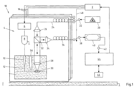
Fig. 1 shows an ultrasonic testing system according to the
invention which is provided with a transmitting apparatus
according to the invention and a receiving system according
to the invention. Furthermore, a method according to the
invention can be carried out using this ultrasonic testing
system.
The measuring arrangement illustrated in Fig. 1 firstly
comprises a control 2 which performs and coordinates the
control of the components, described in the following, of the
ultrasonic testing system.
First of all, the mode of operation of a transmitting
apparatus 4 for an ultrasonic testing system for testing a
test object will be explained. The transmitting apparatus 4
RO/sw 100357W0
4. Oktober 2011
CA 02757715 2011 10 05
- 17 -
comprises transmitting electronics 6, an ignition coil 8 and
an electrode 10 which together form a transmitting apparatus.
The ignition coil 8, together with the electrode 10, presents
means for generating a spark gap 12, wherein the spark gap 12
generates an ultrasonic vibration on the surface and/or
within the test object 14.
The control 2 transmits a control signal to the transmitting
electronics 6 via a line 16, as a result of which a precise
temporal sequence, in particular with regard to the ignition
time and ignition duration, is achieved for generating the
spark gap 12. The transmitting electronics 6 interrupts the
direct current on the primary side of a transformer arranged
in the ignition coil, as a result of which a voltage
sufficient for generating the spark gap 12 is generated on
the secondary side by the breaking-down magnetic field.
Instead of an ignition coil arrangement, it is also possible
to provide an ignition capacitor, although the voltage
generated by the control electronics 6 must be sufficient per
se in order to charge the capacitor to such an extent that it
can ignite the spark gap.
In Fig. 1, three schematic planes 18 indicate that a
multitude of transmitting units is arranged parallel next to
one another. In this respect, the term "plane" is not to be
understood as meaning that those arranged there are arranged
geometrically in one plane, but that each "plane" comprises a
separate arrangement and the different arrangements are
arranged parallel to one another.
Provided in each plane 18 are transmitting electronics 6, an
ignition coil 8 and an electrode 10 which are controlled by
the control 2 via one of the lines 16. Thus, the transmitting
units arranged in parallel to one another can generate in
RO/sw 100357WO
4. Oktober 2011
CA 027577152011-10 05
- 18 -
series spark gaps 12 to induce ultrasonic pulses at different
points on the surface of the test body 14.
According to the invention, the transmitting apparatus can
consist of one or more transmitting units, depending on the
requirements imposed on the test body to be measured.
Fig. 1 also shows a receiving system for an ultrasonic
testing system. A laser 20 generates a laser beam which is
inducted by an optical switch 22 into a light guide 24, or an
optical waveguide (OWG). The light guide 24 transmits the
light onto a measurement area 30 in a first plane 18 by means
of a suitable optical system 26 and 28.
The light reflected from the measurement area 30 is coupled
out of the light path by a beam splitter 32 and is inducted
into a light guide 36 by a suitable lens 34. An optical
switch 38 then couples the light out of the light guide 36
and inducts it into an interferometer 40. A detector 42
generates an output signal which is transmitted into an
evaluation unit 44. There, the signal is evaluated in the
conventional manner with A/D transformation and real time
signal processing, the result of which is transferred to a
computer 46.
If a surface vibration occurs, for example due to an
ultrasonic wave spreading out in the test body, then a
Doppler shift of the reflected light takes place in
particular in the normal direction. These phase- or
frequency-modulated light vibrations are then transformed
interferometrically into an amplitude-modulated signal which
can be measured by a photodetector.
The previously described construction is provided in a large
number of planes 16, in each of which a previously described
receiver unit is arranged in order to be able to capture a
multitude of measurement areas 30. The control 2 then
RO/sw 100357WO
4. Oktober 2011
CA 027577152011-10 05
- 19 -
controls via a line 48 the two optical switches 22 and 38
such that they assume different positions. Thus the laser
light is inducted into the light guide 24 at the same time as
the reflected light, picked up by the light guide 36, is
guided onto the interferometer 40. Therefore, both light
guides 22 and 38 are "active" at the same time. By an
alternating switching to of the respective light paths and
thus of the adjacently arranged receiver units, a
multiplexing of the receiving system is thus achieved.
Fig. 1 also shows the cooperation of the transmitting
apparatus and the receiving system of the ultrasonic testing
system.
The control 2 takes over the synchronisation of the
transmitting apparatus and the receiving system. At a
predetermined time, the transmitting electronics 6 is
activated in one of the planes 18 in order to generate by
means of the ignition coil 8 and the electrode 10 a spark gap
12 with a defined start and finish time. The spark gap 12
induces an ultrasonic pulse in the test body 14.
Preferably at the particular moment in time when the spark
gap 12 is generated, but in any case at a time with a defined
time interval to it, the receiving system and in particular
the optical switches 22 and 38 are activated such that the
receiving system is active in the same plane 18 and measures
a surface vibration based on the ultrasonic signal. The
components of the receiving system in the respective plane 18
are left switched to active until a period of time has
elapsed which is long enough for a run time measurement. This
time period depends on the material parameters and on the
thickness of the test body and is, for example 30 to 50 ps.
Thus, both the transmitting apparatus and the receiving
system can be activated in different planes successively in
RO/sw 100357WO
4. Oktober 2011
CA 02757715 2011_10.05
- 20 -
time. Due to the time sequence of the activation of the
planes, adjacently located measurement areas can be captured.
Thus a grid of measurement areas is detected successively. If
the test body moves transversely to the arrangement of the
planes or if the transmitting and receiving systems move over
the body to be tested and if the width of the arrangement of
the planes or the movement amplitude of the transmitting and
receiving systems substantially corresponds to the width of
the test body, then the entire test body can be successively
examined in a narrow grid of measurement areas.
Fig. 1 also shows that a screen 50 is provided between the
spark gap 12 and the measurement area 30, which screen 50
screens the intensive light, occurring during generation of
the spark gap 12, from the measurement area 30. In addition,
the signal-to-noise ratio can be further improved by the use
of suitable optical band filters which preferably only allow
through the wavelength range of the laser light. For example,
such an optical filter can be arranged between the beam
splitter 32 and the lens 34.
Fig. 2 to 4 show examples of signals which are recorded
during a run time measurement. The output signal of the
interferometer is shown at the top in each case, while the
lower curve shows the envelope (for example the quadrature-
demodulated signal or the low pass-filtered course of the
upper measurement curve). The labelling of the x-axis of the
diagrams represents the sampling points of the signal which
correspond to an arbitrary unit of time. The y-axis
represents the respective intensity of the curve in arbitrary
units.
Fig. 2 shows an idealised, noise-free and undisturbed signal.
A vibration can be seen at regular intervals, the amplitude
of which becomes smaller from one incidence to the next.
RO/sw 100357WO
4. Oktober 2011
CA 02757715 2011_10.05
- 21 -
These vibrations are generated by the ultrasonic signal which
is repeatedly reflected on the surface of the test body
opposite the observed surface. As a result of repeatedly
passing through the test body, the amplitude of the signal
decreases. The signal path shown in Fig. 2 is undisturbed,
because only the regularly occurring vibration signals arise.
The thickness of the test body can be calculated from the
intervals of the maxima in the lower curve, when the speed of
sound inside the test body is known.
Fig. 3 shows an idealised, noise-free signal which this time
is disturbed. It is possible to see at regular intervals
firstly a vibration, as in Fig. 2, the amplitude of which
becomes smaller from one incidence to another. Between each
pair of vibration cycles, there are respectively smaller
signals, which indicates a shorter run time of the ultrasonic
signal inside the test body. Such an additional signal can be
the result of a disturbance inside the test body which
produces a reflection of the ultrasonic wave in the region
between the two surfaces. Thus, this additional signal or its
frequency and amplitude of occurrence can be used as a
measure of the quality of the test body.
Finally, Fig. 4 shows the signal represented in Fig. 3 with a
superimposed noise, so that these measurement curves
represent a realistic case. It should be recognised that the
determination of the maxima is complicated by the noise. For
this reason, when the interferometer is selected, attention
must always be paid to the signal-to-noise ratio to be
achieved thereby.
RO/sw 100357WO
4. Oktober 2011