Note: Descriptions are shown in the official language in which they were submitted.
CA 02757806 2011-11-14
COMPACT PRINTER WITH PRINT FRAME INTERLOCK
BACKGROUND
[0001] The present disclosure relates to continuous feed printers, and more
particularly, to a
compact label or thermal printer having an articulating print frame assembly
having a lockout
link and a swinging media guide. The disclosed printer also includes a fixed
or adjustable media
sensor, and is configurable to accommodate an internal supply of web (roll)
media or an external
supply of fanfold media.
[0002] Compact or desktop printers are often used in commercial settings,
e.g., in
warehouses, in industrial and manufacturing environments, by shipping
services, in restaurants,
in the vending and gaming industries, and in other establishments for ticket
printing, asset
tracking, and inventory control. Ideally, compact printers weigh only a few
pounds and are small
enough to be readily provisioned in a work environment without significant
site preparation.
Such a printer may be operatively associated with an internal or external
power supply that
converts line voltage to the operating voltage(s) required by the printer. The
printer may
additionally or alternatively include a power source, such as a disposable or
rechargeable battery,
and may additionally communicate with a host terminal or network connection
via a wired or
wireless interface, such as an RS-232, Ethernet, USB, WiFi, Bluetooth, or
optical interface.
[0003] A compact printer may utilize sheet-fed media, or, more popularly,
continuous-feed
media, e.g., rolls of paper, labels, tags, and the like. Compact printers
commonly employ direct
thermal transfer techniques, whereby thermochromic media passes over a thermal
print head
1
CA 02757806 2011-11-14
which selectively heats areas of the media to create a visible image. Also
popular are thermal
transfer printers which employ a heat-sensitive ribbon to transfer images to
media.
[0004] A continuous feed printer is particularly suitable for printing onto
stock material
which may include, but is not necessarily limited to, labels, receipts, item
labels, shelf
labels/tags, ticket stubs, stickers, hang tags, price stickers, and the like.
Such media may be
provided in web or roll configuration, or alternatively may be provided in a
fanfold
configuration, whereby individual media units (e.g., sheets or tags) are
joined at the
corresponding edges thereof and stacked in a zigzag manner.
[0005] In the case of continuous roll media, the media may be wound around a
generally
tubular core which supports the roll media. The core may have a standard size,
or arbitrarily-
sized inner diameter. Roll media is available in a wide range of widths.
[0006] The adjacent edges of contiguous fanfold media units may include
scoring or
perforations to facilitate stacking and/or separation of the individual media
units. Fanfold media
may also be provided in a wide variety of widths.
[0007] Label printers may incorporate a media supply of self-adhesive labels
adhered to a
coated substrate wound in a rolled configuration. Alternatively, a media
supply may include a
plain paper roll suitable for ink-based, toner-based, direct thermal-based, or
thermal transfer-
based printing. During use, media may be drawn against a printing head, which,
in turn, causes
images to be created on the media stock by, e.g., impact printing (dot matrix,
belt printing), by
localized heating of thermochromic media (direct thermal printing), by
transferring temperature-
sensitive ink from a ribbon to the print media (thermal transfer printing),
inkjet printing, toner-
based printing, or other suitable printing methods.
2
CA 02757806 2011-11-14
[0008] Compact or thermal printers may be designed for use with one type of
printing media
or one particular size of print media, e.g., 2-inch label stock or 3-inch
label stock. Other compact
printers may be configurable to accommodate different media types and sizes.
Such printers
may include a media centering mechanism which is designed to accommodate roll
media of
varying widths and/or core diameters. The media centering mechanism may
include opposing
support members configured to engage the media roll core. A media centering
mechanism
typically includes first and second support members that are generally biased
towards each other
to secure the media roll. Movement of the first and second support members may
be
synchronized by one or more gears or belts such that, when a support member is
moved a
distance from the centerline of the media roll, the other support member moves
a corresponding
distance in the opposing direction from the centerline of the media roll.
[0009] A compact printer that readily accommodates many different media types
and sizes,
provides improved reliability and performance, and enables facile operation
and reconfiguration
by a casual user, would be a welcome advance in the state of the art.
SUMMARY
[0010] The present disclosure is directed to a compact printer. The printer
includes a
housing having a bottom chassis, and a hinged top cover that is operatively
associated with an
articulating print frame assembly contained therein. The top cover is
selectively movable from a
closed position, suitable for printer operation, to an open position. The open
position of the top
cover is suitable for the loading of media, e.g., roll media or fanfold media,
and for the
configuration of the printer for the desired media, e.g., adjustment or
installation of media guide
elements as discussed in detail herein. The print frame assembly includes
supports for a transfer
ribbon supply roll and a transfer ribbon take-up roll, and is pivotable from a
closed position,
3
CA 02757806 2011-11-14
wherein the print frame is pivoted towards the top cover, to an open position
wherein the print
frame swing away from the top cover to provide access to the supply ribbon
support and the
take-up ribbon support. A print head is operatively positioned between the
supply. During use,
transfer ribbon is supplied from the transfer ribbon supply roll, over a print
head, and to the
transfer ribbon take-up roll.
[0011] The disclosed printer includes a lockout link that cooperates with the
top cover and
print frame assembly that prevents the top cover from being moved from an open
to a closed
position when the print frame is in an open position.
[0012] The print frame includes a transverse media guide bar pivotably mounted
thereto.
The media guide includes a biasing member, e.g., a torsion-spring, that biases
the guide bar
against the ribbon to take up slack and maintain tautness along the ribbon
traversal. The guide
bar include a smooth, arcuate surface over which the media passes and which
facilitates
unwavering deliver of media and transfer ribbon to the print head, which
improves print quality
and reduces the likelihood of malfunction, e.g., jams, irregular print, and
the like.
[0013] The disclosed printer also includes a media sensor that may be
provisioned in a fixed
configuration or an adjustable configuration. The disclosed printer may be
additionally or
alternatively be configured to accommodate an internal supply of web (roll)
media, or an
external supply of fanfold media. A selectively installable set of fanfold
guide members are
disclosed that, when installed, facilitate feeding of fanfold media in a
smooth and controlled
manner through the media path. To facilitate external media feeding, the
disclosed printer
additionally includes a media feed opening defined in the housing that is
substantially aligned
along a plane described by the optional guide members.
4
CA 02757806 2011-11-14
[00141 In another aspect, a compact printer in accordance with the present
disclosure
includes a dual wall, frame housing that provides improved strength and shock
resistance. The
dual wall construction includes a continuous inner frame structure adapted to
support one or
more internal printer components, which may include, without limitation, a
printhead, a roller
assembly, a drive assembly, media centering assembly, and/or a battery
assembly. The inner
frame is surrounded at least in part by a second, outer structure that
provides additional stiffness,
strength, and drop resistance. The housing includes a media access opening and
a corresponding
media access cover configured to facilitate the loading of media into the
printer. The size of the
media access opening is kept to the minimum size necessary to accommodate the
media for use
with the printer. By minimizing the media opening, greater space is available
for the inner frame
and/or the outer structure, further improving the strength, rigidity, and
impact resistance of the
printer.
[00151 The disclosed printer may include one or more connectors that extend
from the
interior of housing to the exterior. While the connector(s) may include an
electrical connector,
other connector types are contemplated within the scope of the present
disclosure, e.g., moisture-
proof connectors, fluidic connectors, security connectors (e.g., K-Slot), and
the like. In
embodiments, two electrical connectors are provided, wherein a first connector
is adapted to
couple a source of electrical power to the printer and a second connector is
adapted to couple a
data signal to the printer. In embodiments, the disclosed printer may include
a USB connector, a
serial (e.g., RS-232, RS-422, RS-485), connector, a Firewire (IEEE-1394)
connector, a network
(l OBase-T, 10OBase-TX, and 1000Base-T) connector, and/or a parallel (IEEE
1284) connector.
[00161 Also disclosed is print frame lockout mechanism. The mechanism includes
an upper
chassis that is pivotable about a hinge between a closed position and an open
position. An
CA 02757806 2011-11-14
arcuate friction member is disposed about the hinge and includes a notch
defined therein. A
print frame is pivotably coupled to the upper chassis and is movable between a
closed position
and an open position. The mechanism further includes a lockout link having a
first end operably
coupled to the print frame, and a second end having a pawl. When the print
frame is in an open
position, the pawl engages the notch, which, in turn, prevents the upper
chassis and/or cover
from pivoting. The arcuate friction member may include one or more detents
configured to
support the upper chassis in a fixed position. The disclosed mechanism may
additionally or
alternatively include a first pin extending from the print frame assembly that
is configured to
engage a corresponding opening defined in an upper portion of the lockout
link, a second pin
extending from the upper chassis, and a slot defined in the lockout link that
slidably engages the
second pin.
[0017] In an embodiment, a compact printer in accordance with the present
disclosure
includes a bottom housing having a top cover coupled thereto. The top cover is
adapted to rotate
away from the bottom housing to an open position and rotate toward the bottom
housing to a
closed position. The compact printer includes a print frame assembly coupled
to the top cover
that is adapted to rotate out of the top cover to an open position and to
rotate into the top cover to
a closed position. When the print frame is in an open position, the top cover
is prevented from
rotating toward the bottom housing to a closed position. The disclosed printer
may include a
means for retaining the print frame assembly in a closed position, such as
without limitation, a
latch. The print frame includes a print head for transferring indicia onto the
print media.
[0018] A media sensor may be disposed along the path of the print media (e.g.,
the feed
patch) and in an embodiment may be adjustable along an axis transverse to the
print path. In
embodiments, the print frame assembly may include a media guide pivotably
mounted thereto by
6
CA 02757806 2011-11-14
at least one side arm. The media guide includes a biasing member, such as
without limitation, a
torsion-spring, that is configured to bias the media guide outward from the
print frame assembly.
The media guide may include an arcuate media-contacting surface. In
embodiments, the printer
includes first and second media support members that are reciprocally movable
along a
transverse axis of the printer and configured to support roll media held
therebetween. An
adjustable stop selectively adjustable along a transverse axis of the printer
and adapted to prevent
transverse motion of a media support member may additionally be included. In
embodiments,
the support member may configured to operably engage a fanfold guide. An
elongate opening in
an outer surface of the printer may be provided to facilitate the feeding of
external media into the
fanfold guide.
[00191 Also disclosed is a fanfold guide that is selectively coupleable to a
media support
member of a compact printer. The fanfold guide includes an elongate member
having a channel
defined therein adapted to accept the edge of print media, wherein an end of
the channel includes
a flared portion. A tab is disposed on the elongate member adapted to operably
engage a
corresponding slot defined in the media support member, and a recess is
defined in an edge of
fanfold guide that is adapted to operably engage a corresponding protrusion
defined in the media
support member. The tab-and-recess combination promotes proper and secure
alignment of the
fanfold guide with the media support member.
7
CA 02757806 2011-11-14
BRIEF DESCRIPTION OF THE DRAWINGS
[0020] Various embodiments of the subject instrument are described herein with
reference to the drawings wherein:
[0021] Fig. 1 is a view of an example embodiment of a compact printer in
accordance with
the present disclosure having a top cover in a closed position;
[0022] Fig. 2 is a view of the Fig. 1 embodiment of a compact printer in
accordance with the
present disclosure having a top cover in an open position and a print frame in
an open position;
[0023] Fig. 2A is a view of the Fig. 1 embodiment of a compact printer in
accordance with
the present disclosure having a top cover in an open position and a print
frame in a closed
position;
[0024] Fig. 3 is a view of print frame module, lower chassis, and a lockout
link of an
example embodiment of a compact printer in accordance with the present
disclosure;
[0025] Fig. 4 is an alternative view of the Fig 3. print frame module, lower
chassis, and
lockout link;
[0026] Fig. 5 illustrates a print frame module and lockout link in an open
position in
accordance with the present disclosure;
[0027] Fig. 5A illustrates a print frame module and lockout link in a closed
position in
accordance with the present disclosure;
[0028] Fig. 6 is a detail view of an example print frame module of an
embodiment of a
compact printer in accordance with the present disclosure;
8
CA 02757806 2011-11-14
[0029] Fig. 7 is a detail view of the Fig. 6 print frame showing a media guide
bar in
accordance with the present disclosure;
[0030] Fig. 8 is a detail view of an example embodiment of a compact printer
in accordance
with the present disclosure having an adjustable media sensor;
[0031] Fig. 9 is a view of an example embodiment of an adjustable media sensor
assembly in
accordance with the present disclosure;
[0032] Fig. 10 is a detail view of an example embodiment of a compact printer
in accordance
with the present disclosure having a fixed media sensor;
[0033] Fig. 11 is a perspective view of an example embodiment of a compact
printer in
accordance with the present disclosure configured with fanfold guides;
[0034] Fig. 12 is another view of the Fig. 11 example embodiment showing a
relationship
between a media feed opening and fanfold guides; and
[0035] Fig. 13 is view of a media support member in relation to a removable
fanfold guide.
DETAILED DESCRIPTION
[0036] Particular embodiments of the present disclosure are described
hereinbelow with
reference to the accompanying drawings; however, it is to be understood that
the disclosed
embodiments are merely exemplary of the disclosure, which may be embodied in
various forms.
Well-known and/or repetitive functions and constructions are not described in
detail to avoid
obscuring the present disclosure in unnecessary or redundant detail.
Therefore, specific
structural and functional details disclosed herein are not to be interpreted
as limiting, but merely
as a basis for the claims and as a representative basis for teaching one
skilled in the art to
variously employ the present disclosure in virtually any appropriately
detailed structure. In
9
CA 02757806 2011-11-14
addition, as used herein, terms referencing orientation, e.g., "top"bottom",
"up", "down",
"left", "right", "clockwise", "counterclockwise", and the like, are used for
illustrative purposes
with reference to the figures and features shown therein. It is to be
understood that embodiments
in accordance with the present disclosure may be practiced in any orientation
without limitation.
In this description, as well as in the drawings, like-referenced numbers
represent elements which
may perform the same, similar, or equivalent functions.
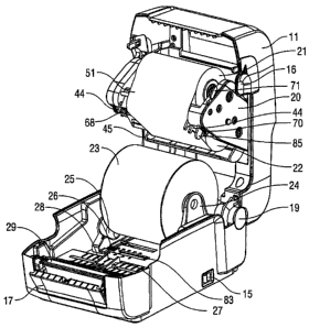
[0037] Figs. 1 and 2 present an example embodiment of a compact printer 10 in
accordance
with the present disclosure. The printer 10 includes a bottom housing 18 and a
selectively
positionable top cover 11 that may be positioned in a closed position as shown
in Fig. 1 and an
open position as shown in Fig. 2. Top cover 11 and bottom housing 18 are
pivotably joined by a
hinge 19. Top cover 11 includes a user interface panel 12, one or more user
input devices 14,
and one or more indicators 13. User interface panel many be any suitable form
of display panel,
including without limitation an LCD screen. User input device may be any
suitable form of
input device, e.g., a snap dome or membrane pushbutton switch. Indicator 13
may be any
suitable indication, such as without limitation a light-emitting diode (LED).
Indicator 13 may
illuminate to indicate the status an operational parameter, e.g., power,
ready, media empty, media
jam, self test, and the like. Printer 10 includes a power switch 15. A pair of
latches 16 are
disposed on either side of top cover 11 to retain top cover 11 in a closed
position, and may be
disengaged using finger pressure to facilitate opening of top cover 11. A
media door 17 provides
an alternative point of egress for media, which may be advantageous with self
adhesive labels
whereby the labels peel away from the substrate upon exiting the printer.
[0038] With regard to Figs. 2 and 2A, top cover 11 includes a print frame
assembly 20
pivotably mounted therein. Print frame assembly 20 includes a ribbon supply
roll 22 and a
CA 02757806 2011-11-14
ribbon take up roll 21 that are arranged to supply transfer ribbon 51 across a
print head 68. Print
frame assembly 20 is selectively positionable between an open position as
shown in Fig. 2 and a
closed position as shown in Fig. 2A. Print frame assembly 20 includes a latch
71 that engages a
retaining pin (not explicitly shown) provided within top housing 11 to retain
print frame
assembly 20 in a closed position. A release 70 is operatively associated with
latch 71 such that,
when depressed, releases latch 71 from the retaining pin to enable print frame
assembly 20 to
swing outward to an open position.
[0039] Printer 10 includes a first and a second media support members 24, 25,
respectively,
that are configured to support roll media 23 held therebetween. Media support
members 24 and
25 are moveable along a transverse axis and are operatively associated with a
reciprocal
movement mechanism (not explicitly shown) that is configured to translate a
transverse
movement of first media support member 24 into a corresponding opposite
transverse movement
of second media support member 25, and vice versa. By this arrangement, roll
media 23 of
arbitrary width may be accommodated while concurrently centering roll media 23
with respect to
the longitudinal axis "A-A" of the print head 68 and thus to the centerline of
a feed path 76
corresponding thereto. First and a second media support members 24, 25 may be
biased
inwardly, e.g., toward the centerline, by a biasing member, e.g., a spring
(not explicitly shown),
to aid in gripping media roll 23 between the support members 24, 25. A
selectively adjustable
stop 26 enables the position of media support members 24, 25 to be preset.
Stop 26 is slidably
disposed within an elongated slot 83 transversely defined in feed path 76 of
lower chassis 34.
Stop 26 and elongated slot 83 are configured to provide sufficient friction
through mechanical
detents and discrete positions therebetween to enable stop 26, when
positioned, to overcome the
11
CA 02757806 2011-11-14
inward biasing force of media support members 24, 25 and maintain media
support members 24,
25 in the desired position.
[0040] A first media guide member 27 and a second media guide member 28 are
moveable
along a transverse axis and are operatively associated with a second
reciprocal movement
mechanism (not explicitly shown) that is configured to translate a transverse
movement of first
media guide member 27 into a corresponding opposite transverse movement of
second media
support member 28, and vice versa. A platen roller 29 opposes print head 68
when top cover 11
is in the closed position to ensure intimate contact between print head 68,
transfer ribbon 51, and
media 23 during use, which, in turn, promotes consistent high print quality.
Print head 68
includes a pair of fork-like saddles 44 that engage a portion of platen roller
29 to ensure precise
alignment between print head 68 and platen roller 29 when top cover 11 is in a
closed position.
A tab 85 extends from print frame assembly 20 that is configured to engage a
corresponding slot
(not explicitly shown) provided in bottom housing 18 to enable the top cover
11 and/or the print
frame 20 to close while ensuring the saddles 44 smoothly engage the platen
roller 29 and/or a
bushing (not explicitly shown) associated therewith.
[0041] Turning now to Figs. 3, 4, 5, and 5A, printer 10 includes a lockout
link 30 that
prevents closure of the top cover 11 when print frame assembly 20 is in an
open position. An
upper chassis 39 is provided within top cover 11. Print frame assembly 20 is
pivotably joined to
upper chassis 39 by a pair of pivots 72. A pair of arcuate friction members
32, 33 are disposed
about hinge 19. A series of detents 36 on friction member 32, and a series of
detents 37 on
friction member 33 engages corresponding slots 73, 74, respectively, in upper
chassis 39, which
facilitates the positioning of top cover 11 in a fully open position, a fully
closed position, and
several intermediate positions therebetween.
12
CA 02757806 2011-11-14
[0042] As best seen in Figs. 5 and 5A, lockout link 30 is configured to
prevent closure of the
top cover 11 when print frame assembly 20 is in an open position. Print frame
assembly 20
includes a pin 69 operably coupled print frame assembly 20 to an upper portion
of lockout link
30. Lockout link 30 include slot 31 that slidably engages pin 41 of upper
chassis 39 to facilitate
the articulation of lockout link 30 when print frame 20 is moved between open
and closed
positions. In the open position, print frame assembly 20 is pivoted forward on
pivot 72, causing
the lockout link 30 to ride upward and to rotate slightly clockwise on pin 41,
which, in turn,
causes pawl 38 of lockout link 30 to engage notch 75 of friction member 32. In
this position,
i.e., when pawl 38 of lockout link 30 is engaged with notch 75, top cover 11
is prevented from
moving to a closed position, e.g., top cover 11 cannot be pivoted
counterclockwise.
[0043] As print frame 20 moves clockwise from an open position to a closed
position, pin 69
moves upward and leftward about pivot 72, which, in turn, rotates lockout link
30
counterclockwise and draws lockout link 30 upward, thereby disengaging pawl 38
from notch 75
and establishing sufficient clearance between the lower portion of lockout
link 30 and friction
member 32 to enable top cover 11 to be moved into a closed position.
[0044] Turning to Figs. 6 and 7, print frame 20 includes transverse media
guide 45 pivotably
mounted thereto by side arms 49. Pins 48 engage a corresponding opening (not
explicitly
shown) provided in an inner side wall 52 of print frame 20 to facilitate
pivoting motion of guide
bar 45. The media guide 45 includes a biasing member 46, e.g., a torsion
spring or a leaf spring,
that biases guide bar 45 outwardly from ribbon supply roll 22. During use,
ribbon 51 passes
under media guide 45 which, in turn, guides the media 23 and maintains the
path separate from
the ribbon 51. Media guide bar 45 includes a smooth, arcuate surface 50 over
which media 23
passes and which promotes the steady delivery over print head 68.
13
CA 02757806 2011-11-14
[0045] Printer 10 includes an adjustable media sensor assembly 53 transversely
disposed in
lower chassis 34 across a feed path 76. Adjustable media sensor assembly 53
includes an
elongated cavity 57 having a media sensor 54 slidably disposed therein. Media
sensor 54 is
selectively positionable along cavity 57, which enables media sensor 54 to be
aligned with index
marks, media gaps, or other positional indicia characteristic of the print
media, which, in turn,
enables printer 10 to accurately feed and position media during use. Media
sensor 54 includes an
aperture 55 defined therein to enable a sensing element (not explicitly
shown), such as without
limitation a photodiode, to sense media indicia. In an alternative embodiment,
printer 10
includes a fixed media sensor 59 having an aperture 60 defined therein to
enable a sensing
element (not explicitly shown), such as without limitation a photodiode, to
sense media indicia
therethrough. Media sensor 54 and/or fixed media sensor 59 are aligned with
and cooperate with
an excitation element 86, e.g., a light emitting diode, disposed on print head
68 such that a light
beam emitted from excitation element 86 is detectable by media sensor 54
and/or fixed media
sensor 59. Media sensor 54 and/or fixed media sensor 59 may thus sense when
the light beam is
interrupted or reduced in intensity by a portion of media passing between
media sensor 54 and/or
fixed media sensor 59, and excitation element 86.
[0046) In a non-limiting example, a roll of self-adhesive label media includes
a series of
discrete labels disposed on a continuous length of backing material. A gap
exists between
successive labels where only the backing material is exposed. As the gap
passes between the
sensing element and the excitation element, the level of light transmitted
from the excitation
element to the sensing element varies, enabling the detection of the edges of
individual media
labels.
14
CA 02757806 2011-11-14
[0047] In embodiments, the position of the sensing element (not explicitly
shown) and
excitation element 86 may be swapped while keeping within the spirit and scope
of the present
disclosure. In an embodiment, the position of excitation element 86 is
adjustable along a
transverse axis of motion (e.g., across the width of print head 68) to
coordinate the alignment of
excitation element 86 with the position of media sensor 54. Graduations 87 may
be provided
adjacent to excitation element 86 to facilitate the alignment of excitation
element 86 via
corresponding graduations 88 provided adjacent to media sensor 54.
[0048] Advantageously, lower chassis 34 includes a scored opening 77 that
eliminates the
need for separate tooling to produce a printer 10 with an adjustable media
sensor assembly 53 or
a printer 10 with a fixed media sensor assembly 59. During manufacturing, a
removable member
78 may be removed from scored opening 77 to provide the appropriate opening to
facilitate
installation of adjustable media sensor assembly 53. Alternatively during
manufacture,
removable member 78 may be retained and fixed media sensor 59 joined thereto.
[0049] With reference to Figs. 11, 12, and 13, printer 10 may include a pair
of fanfold guides
61, 62 that are configured to facilitate feeding non-roll media through
printer 10. Fanfold guides
61, 62 may have substantially identical construction with the exception that
fanfold guide 61
may be a mirror image of fanfold guide 62. Accordingly, and for the sake of
brevity, the
following description of fanfold guide 61 is applicable to the corresponding,
reciprocal features
of fanfold guide 62. Media support member 24 includes similar reciprocal
features to those of
media support member 25 as will be described in detail below.
[0050] Fanfold guide 62 has an elongate construction and includes a front
portion 81, a rear
portion 80, and a channel 79 defined therein that is adapted to accept the
edge of print media
during use. Rear portion 80 of channel 79 open to a flare 63 that is adapted
to facilitate easy
CA 02757806 2011-11-14
threading of media by a user. Flare 63 is aligned with an elongate media
opening 65 defined in
the bottom housing 18, as best seen in Fig. 12, though which media, such as
without limitation
fanfold media, is fed into printer 10. A lip 64 extends from the front portion
81 of fanfold guide
61 to promote a smooth and jam-free exit of media therefrom.
[00511 Fanfold guide 62 includes features designed to enable the selective
coupling thereof
to corresponding features provided by media support member 25. A pair of tabs
84 are disposed
on fanfold guide 62 that are adapted to operably engage a corresponding slot
67 defined in media
support member 25. A recess 66 is defined in a closed edge 82 of fanfold guide
62 to promote
horizontal alignment of fanfold guide 62 with media support member 25 when
fanfold guide 62
and media support member 25 are engaged. During use, printer 10 may be
reconfigured from a
roll media configuration to a fanfold or external media configuration by
removing media roll 23,
if present, and attaching fanfold guides 61, 62 to media support members 24,
25. Media support
members 24, 25 may additionally be adjusted for width as described
hereinabove, and retained in
place by slidably adjusting stop 26, as needed.
[00521 The described embodiments of the present disclosure are intended to be
illustrative
rather than restrictive, and are not intended to represent every embodiment of
the present
disclosure. Further variations of the above-disclosed embodiments and other
features and
functions, or alternatives thereof, may be made or desirably combined into
many other different
systems or applications without departing from the spirit or scope of the
disclosure as set forth in
the following claims both literally and in equivalents recognized in law.
16