Note: Descriptions are shown in the official language in which they were submitted.
CA 02757970 2011-11-08
Inventor: Robert F. Stalcup H, et al.
Docket No. 55615.10030
Title: Exhaust Connection Member with Preformed Braided Cover
EXHAUST CONNECTION MEMBER WITH PREFORMED BRAIDED COVER
CROSS-REFERENCE TO RELATED APPLICATIONS
[Non None.
BACKGROUND OF THE INVENTION
[0002] As is generally known, some automotive exhaust systems employ a
flexible connection
member or coupler disposed between two exhaust pipes in order to absorb
undesirable vibrations
input into the exhaust piping, absorb any thermal expansion or contraction of
the exhaust piping,
and compensate for any misalignments in the exhaust piping. These couplers are
generally
formed of an inner flexible metal bellows member and an outer braid cover
surrounding the outer
periphery of the bellows member. Exemplary of such a coupler is U.S. Patent
No. 5,769,463 to
Thomas. The braid cover is normally in very close proximity to, if not in
direct contact with, the
bellows. Such a placement of the braid cover often leads to friction between
the bellows and the
braid cover thereby resulting in wearing and premature failure of the bellows
and braid cover. In
currently known embodiments where the braid cover is spaced at any significant
distance from
the bellows member, such as in U.S. Patent No. 6,902,203 to Kang, the braid
cover has to be
supported by some rigid support means in order to maintain that spacing.
[0003] It is well known in the industry that one source of energy loss
and inefficiency in internal
combustion engines is the loss of heat through exhaust gases. Heat lost though
the engine's
exhaust gas results in a loss of energy that would otherwise be in the form of
mechanical energy
produced by the engine. Furthermore, keeping heat in the exhaust gases speeds
the gases up in
KCP-4044155-2 1
CA 02757970 2014-12-11
64005-1497
their travel though the exhaust system thereby reducing the amount of back
pressure on the
engine. Thus, it is desirable for internal combustion engines to have exhaust
systems that lose as
little heat as possible.
[0004] It is also known in the industry to construct the braid cover
of many bundles of
fine metal wires. The bundles are knitted alternatively to each other in a
spiral direction.
Normally, the spacing between the bundles and the density of the braid cover
is not of
importance other than to ensure that the braid cover generally protects the
bellows from sand,
gravel and other road debris. It is unknown in the prior art to form the braid
cover in a manner
wherein it creates a thermally insulating layer around the bellows.
[0005] Accordingly, a need exists for a braid cover that includes a self-
supporting
portion spaced at a distance from a bellows member in order to create a
meaningful air gap
therebetween. A need also exists for a method for manufacturing such a braid
cover. A further
need exists for a coupler that has increased insulating properties in order to
maintain heat
within the exhaust gas flowing through the coupler.
SUMMARY OF THE INVENTION
[0005a] According to an aspect of the present invention, there is
provided a coupler for
use in an exhaust system, said coupler comprising: a flexible bellows member
made of
metallic material and having a generally cylindrical and repeatedly corrugated
shape; an outer
braid cover surrounding an outer periphery of said bellows member, said braid
cover being
formed into a predetermined shape prior to assembly with said bellows such
that a portion of
said braid cover is maintained at a predetermined space from corrugations of
said bellows
member; and a retainer for combining end parts of said bellows member and said
braid cover.
[0005b] According to another aspect of the present invention, there is
provided a
coupler for an exhaust system, comprising: a flexible bellows including a
generally cylindrical
corrugated body that is formed from a metallic material, a braid cover
extending over the
bellows from a first end to a second end such that a gap is defined between
the braid cover
and the corrugated body of the bellows, a retainer secured to the corrugated
body and the
2
CA 02757970 2014-12-11
64005-1497
braid cover, wherein the first end of the braid cover is received in a closed
pocket defined in
the retainer.
[0005c] According to another aspect of the present invention, there is
provided a
coupler for an exhaust system, comprising: a bellows including a generally
cylindrical
corrugated body that is formed from a metallic material, a braid cover
extending over the
bellows, the braid cover including a body section having a first diameter, an
end section
including a neck having a second diameter that is less than the first
diameter, a shoulder
extending radially between the body section and the neck, the shoulder forming
a stiffened
corner to provide the cover with rigidity, a retainer secured to the
corrugated body and the
braid cover, wherein the neck of the braid cover is received in a closed
pocket defined in the
retainer.
[0006] Aspects of the present disclosure involve the provision of an
exhaust
connection coupler and a method for manufacturing a braid cover incorporated
therein. In
some embodiments, the coupler may include an inner flexible bellows member and
an outer
braid cover surrounding the bellows member. In some embodiments, the braid
cover may be
formed into a predetermined shape prior to assembly with the remainder of the
coupler. In
some embodiments, the braid member can include a generally cylindrical body
section and
two end sections each forming necks having diameters that are smaller than the
diameter of
the body section. Such an arrangement enables the body section of the braid
cover to be
positioned at a predetermined space from the bellows member. In some
embodiments, the
unique design of the braid cover is such
2a
CA 02757970 2014-06-10
64005-1497
that the body section is self-supporting and does not require any additional
support means for
maintaining its space from the bellows member. In some embodiments, the braid
member may be formed
of bundles of metallic filaments that are intertwined in a fashion so as to
create a dense coverage over the
bellows member thereby allowing the braid cover to act as a thermally
insulating layer.
In some embodiments, a thermally insulating air gap is defined between the
braid cover and the bellows
member in order increase the amount of heat maintained within exhaust gas
flowing through the coupler.
[0007] Another aspect of the present disclosure is directed to a method
for manufacturing the
braid cover. In this method, wire filaments may be intertwined on a mandrel to
form a sleeve-
like article. The sleeve-like article may then be shaped with forming dies
into a resulting braid
cover. In one embodiment, the sleeve-like article is placed around a male
forming and then
pressed between the male forming die and a female forming die to shape the
article into the
desired shape of the braid cover.
[0008] Other and further features of some embodiments of the invention,
together with the features
of novelty appurtenant thereto, will appear in the course of the following
description.
DESCRIPTION OF ME SEVERAL VIEWS OF THE DRAWING
[0009] In the accompanying drawing, which forms a part of the
specification and is to be read in
conjunction therewith in which like reference numerals are used to indicate
like or similar parts
in the various views:
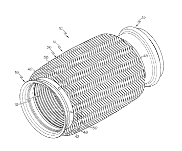
[0010] Fig. 1 is a side perspective view of an exhaust connection
coupler in accordance with one
embodiment of the present invention;
[0011] Fig. 2 is a cut-away side view of an exhaust connection coupler
in accordance with one
embodiment of the present invention;
3
CA 02757970 2014-06-10
64005-1497
[0012] Fig. 3 is an enlarged fragmentary cross-sectional side view of an
exhaust connection
coupler in accordance with one embodiment of the present invention;
[0013] Fig. 4 is a partially enlarged view illustrating the manner and
density at which wire
elements may be braided in order to form a cover member in accordance with one
embodiment
of the present invention;
[0014] Fig. 5 is an exploded side perspective view of a portion of the
tooling used to form the
braid cover in accordance with one embodiment of the present invention;
[0015] Fig. 6 is an exploded cross-sectional side perspective view of a
portion of the tooling
used to form the braid cover in accordance with one embodiment of the present
invention;
[0016] Fig. 7 is a cross-section side view of illustrating the braid
cover being formed by tooling
in accordance with one embodiment of the present invention; and
[0017] Fig. 8 is a side perspective view of a braid cover in accordance
with one embodiment of
the present invention.
DETAILED DESCRIPTION OF EMBODIMENTS
[0018] Examples of embodiments of the invention will now be described
with reference to the drawing
figures, in which like reference numerals refer to like parts throughout. For
purposes of clarity in illustrating
the characteristics of embodiments of the present invention, proportional
relationships of the elements have
not necessarily been maintained in the drawing figures.
[0019] An embodiment of the present invention is directed generally
toward an exhaust connection member
or coupler 10 and a method for manufacturing a braid cover 14 incorporated
therein. As shown in
Fig. 1, the coupler 10 includes a flexible bellows member 12, a braid cover 14
surrounding the
bellows member 12, first and second end flanges 16 and 18, and end rings or
collars 48 for
securing the end parts of the bellows member 12 and braid cover 14 together.
The coupler 10
4
CA 02757970 2011-11-08
Inventor: Robert F. Stalcup II, et al.
Docket No. 55615.10030
Title: Exhaust Connection Member with Preformed Braided Cover
may optionally include an interlock flex liner member (not shown) disposed
inwardly of the
bellows member 12.
[0020] The bellows member 12, which may be formed of a metallic
material, is comprised of
first and second tube-like ends 20 and 22 with a plurality of repeating
corrugations 24 extending
therebetween. The bellows member 12 is flexible thereby serving to effectively
absorb any
linear thermal expansion and contraction of the exhaust piping (not shown) to
which the coupler
is connected, absorb undesirable vibrations input into the exhaust piping and
compensate for
misalignments in the exhaust piping. The bellows member 12 defines a
passageway 26 through
which the exhaust gases flow.
[0021] As illustrated in Figs. 2 and 3, the braid cover 14 surrounds an
outer periphery of the
bellows member 12. The braid cover 14 serves to dampen vibrations, protect the
bellows
member 12, prevent elongation of the bellows member 12 under pressure and form
a thermally
insulating dead space around the bellows member 12 in order to maintain heat
within the exhaust
gases flowing therethrough.
[0022] The braid member 14 is formed of many ribbon-like bundles 32 of
parallel metallic wire
filaments 78. In one embodiment, the bundles 32 are fashioned from a plurality
of metal wires
filaments 78 that are generally in side by side contact with one another to
form a substantially
solid ribbon. The bundles 32 may be intertwined (e.g., interlaced, braided,
knitted, woven,
looped or the like) together on an elongated mandrel (not shown) to form a
flexible, fabric-type
cylindrical article.
[0023] As seen in Fig. 4, two opposing inside edges of two adjacent
bundles 32 (extending
parallel to each other in a first spiral direction) and two opposing inside
edges of two other
adjacent bundles 32 (extending parallel to each other in a second spiral
direction) cooperate to
KCP-4044155-2 5
CA 02757970 2011-11-08
Inventor: Robert F. Stalcup II, et at.
Docket No. 55615.10030
Title: Exhaust Connection Member with Preformed Braided Cover
define a slight rectangular or diamond-shaped aperture 34. In order for the
braid cover 14 to
effectively form a thermally insulating layer around the air space 46 defined
between the bellows
member 12 and the braid cover 14, the braid cover 14 needs to have a tight
pattern in order to
provide a dense coverage. The overall total opening of the apertures 34 with
respect to the
overall area of the outer surface of the cover 14 should be between about 0.5%
and 20%, and
more preferably between about 0.5% and 10%. This high-density pattern is the
result of tightly
intertwining a plurality of metal wire bundles 32. The high-density pattern
results in a braid
cover 14 wherein only a very minimal amount of air from the air space 46 may
permeate
therethrough. The combination of the air gap 46 and the high-density braid
cover 14 serves to
reduce the amount of heat that is lost from the exhaust gases as they travel
though the coupler 10.
The air gap 46 acts as a thermally insulating dead air space surrounding the
bellows member 12
to maintain heat within the exhaust gas flowing through the coupler 10. The
braid cover's 14
high-density pattern further provides the bellows member 12 with increased
protection from
water, melting salt, sand, gravel and other road debris.
[0024] As depicted, the braid cover's first and second ends 28 and 30
are formed into shape such
that a middle body portion 36 of the cover 14 is maintained at a predetermined
space from and is
not in contact with the bellow corrugations 24. This not only prevents wearing
and premature
failure of the bellows member 12 and braid cover 14 thereby resulting in the
coupler 10 having a
longer life, but also serves to create the insulating air gap 46 defined
between the bellows
member 12 and braid cover 14. Each end 28 and 30 may be reduced to form a neck
portion 44
having a smaller diameter than the body portion 36. Stated differently, the
body portion 36 may
extend radially outwardly from and have a larger diameter than each neck
portion 44. The body
portion 36 and at least one of the neck portions 44 may be generally
cylindrical in shape.
KCP-4044155-2 6
CA 02757970 2011-11-08
Inventor: Robert F. Stalcup II, et al.
Docket No. 556 15.10030
Title: Exhaust Connection Member with Preformed Braided Cover
[0025]
As shown in the figures, each end 28 and 30 is formed to include a neck 44 and
a
shoulder 42 extending radially outwardly from the neck 44 to meet the body
portion 36 at a
corner 40. The shoulder 42 and the body portion's wall 38 may converge so as
to be generally
perpendicular with one another. This, in combination with the corner 40 having
a relatively
small radius and the bundles 32 being tightly braided, establishes increased
rigidity in the braid
cover 14 such that the body portion 36 may be self-supporting between the two
shoulders 42.
Unlike the known prior art having an outer braid cover disposed an appreciable
distance from the
bellows, embodiments of the braid cover 14 in the present invention do not
require any
additional support means in order to maintain a predetermined space from the
bellows member
corrugations 24. It should be noted, however, that the angle in which the
shoulder 42 meets the
wall 38 may be greater than or less than 90 degrees and the corners 40 may be
of any suitable
radius, so long as the body portion 36 maintains adequate rigidity to be self
supporting between
the shoulders 42.
[0026]
While both ends 28 and 30 of the braid member 14 are shown as being formed
into
substantially the same shape in the figures, it should be understood that the
two ends 28 and 30
may be formed into different shapes or that, alternatively, only one end 28
may be formed into a
desired shape while the other end 30 may remain in the in generally the same
shape as when
formed on the mandrel.
[0027]
The bellows member ends 20 and 22 may be combined with or secured to the braid
cover
ends 28 and 30, respectively, with a retainer. The retainer may be comprised
of a support ring or
collar 48, a spot weld 50, a clamping member, any suitable fastener, or any
combination thereof.
As best illustrated in Fig. 3, the retainer may also secure the bellow member
ends 20 and 22 and
braid cover ends 28 and 30 to an outer surface of the flanges 16 and 18. As
shown in Figs. 2 and
KCP-4044155-2 7
CA 02 757 97 0 2 011-11¨ 08
Inventor: Robert F. Stalcup H, et al.
Docket No. 55615.10030
Title: Exhaust Connection Member with Preformed Braided Cover
3, the end rings 48 are fit on the flanges 16 and 18 in such a manner as to
sandwich the bellow
member ends 20 and 22 together with the braid cover ends 28 and 30 between the
end rings and
flanges 16 and 18. As may be appreciated by a plurality of spot welds 50, the
bellows member
12, the braid cover 14 and the end rings 49 may be integrally connected to
each other by way of
welding. The end rings 48 may further be secured to the flanges 16 and 18 by
way of a weld 52
or other suitable attachment means. It should be understood, however, that the
bellows member
12 and braid cover 14 may be coupled with the flanges 16 and 18 or directly to
the exhaust pipes
(not shown) by any suitable fastening means, including welding, clamping,
riveting, bolting,
screwing or the like. It should further be understood that the flanges 16 and
18 may be of any
suitable shape and length and may comprise an elbow or offset angle if
desired. Additionally, it
will be appreciated that the end rings 48 may be of any suitable shape and may
each include a
flared or upturned end as is commonly known in the art.
[0028] Turning attention now to the manner in which the braid cover 14
is manufactured, focus
is drawn toward Figs. 5-8. As set forth above, wire filaments 78, in the form
of bundles 32, may
be intertwined (e.g., interlaced, braided, knitted, woven, looped or the like)
together on an
elongated mandrel (not shown) to form a flexible, sleeve-like cylindrical
article 80 like that
depicted in Figs. 5 and 6. The sleeve-like article 80, which has first and
second ends 82 and 84,
may have a generally uniform cross-sectional area about its entire length. in
the manufacturing
process, the sleeve-like article 80 is formed into the braid cover 14.
[0029] Upon the construction of the sleeve-like article 80, one or both
ends 82 or 84 of the
article 80 are formed into shape so as to include a neck 44 and a shoulder 42
extending radially
outwardly from the neck 44 which meets a body portion 36 at a corner 40, like
described above
and illustrated in Fig. 8 among others. This forming may be undertaken by any
suitable method
KCP-4044155-2 8
CA 02757970 2011-11-08
=
Inventor: Robert F. Stalcup II, etal.
Docket No. 55615.10030
Title: Exhaust Connection Member with Preformed Braided Cover
and through the use of a variety of tooling and equipment. In one embodiment,
forming dies 54
and 64 are employed. As shown best in Fig. 6, the outer profile of a male
forming die 54 and the
inner profile of a female forming die 64 generally dictate the shape of the
completed braid cover
14. In one embodiment, the sleeve-like article 80 is placed over or around the
male forming die
54 which may inserted into a female forming die 64 with the article 80 being
located and
compressed therebetween.
[0030] As shown, the male forming die 54 includes a body section 56 and
ends having a neck
section 62 and a shoulder section 60 extending radially outwardly from the
neck section 62 and
meeting the body section 56 at a corner 58. The cross-sectional area of the
neck section 62 is
less than the cross-sectional area of the body section 56. Thus, in one
embodiment, the neck
section may be generally cylindrical and have a diameter that is less than the
diameter of the
body section 56. Again, the outer profile of the male forming die 54 may
generally dictate the
shape of the finished braid cover 14.
[0031] The female forming die 64 may include an inner profile that
generally resembles the
outer profile of the male forming die 54. Depending upon the thickness of the
article 80, the
inner profile of the female forming die 64 may be slightly larger than the
outer profile of the
male forming die 54 so as to accommodate the article 80 therebetween. As
shown, the female
forming die 64 includes a first, larger diameter cavity portion 66 sized and
shaped to
accommodate at least a portion of the male forming die's body section 56 and a
second, smaller
diameter cavity portion 68 sized and shaped to accommodate at least a portion
of the male
forming die's neck section 62. A shoulder 70, resembling the shoulder 60 of
the male foiming
dies 54, extends radially between the first and second cavity portions 66 and
68.
KCP-4044155-2 9
CA 02 757 97 0 2 011-11- 08
Inventor: Robert F. Stalcup II, et aL
Docket No. 55615.10030
Title: Exhaust Connection Member with Preformed Braided Cover
[0032]
After the sleeve-like article 80 is formed, for example on a mandrel, it may
be placed
around the male forming die 54. Once on the male forming die 54, the article
may be held
against the body section 56 of the die 54 with a cinching or retaining device
72 that may be
comprised of piece of sheet metal 74 and clamps or buckles 76. Any, other
suitable means for
holding the article 80 against the die 54 may be used as well.
[0033] As illustrated in Fig. 7, in order to form the sleeve-like
article 80 into the braid cover 14,
one or more end portions of the male forming die 54 with the article 80 placed
therearound may
be inserted into one or more female forming dies 64. The ends 82 and 84 of the
article 80 are
located and compressed between the male forming die 54 and one or more female
forming dies
64. As shown in Fig. '7, the dies 54 and 64 may be aligned with one another
and a force F
applied in an axial direction to bring the dies 54 and 64 together with the
article 80 therebetween.
In one embodiment, the dies 54 and 64 are placed in a press (e.g., hydraulic,
pneumatic or
mechanical press) which generates the force F. In such an embodiment, one
female forming die
64 may be mounted to a base of the press and a second female forming die 64
may be mounted
to the press's ram. The male forming die 54 may be aligned and placed
therebetween. Once in
the male forming die 54 is in position, the ram may be extended thereby
compressing the male
forming die 54 and article 80 between the two female forming dies 64 like
shown in Fig. 7.
When the ram is retracted, the retaining device 72 may be removed from around
the sleeve 80
and the sleeve 80, which is now in the form of the braid cover 14, may be
removed from the
male forming die 54. One of the formed ends 28 or 30 may be slightly expanded
in order to
remove the braid cover 14 from the die 54. The material forming the end 28 or
30 may have
"memory" and once removed from the die 54, the end 28 or 30 may generally
contract back to
the diameter it was formed into between the dies 54 and 64.
KCP-4044155-2 10
CA 02757970 2011-11-08
Inventor: Robert F. Stalcup TI, et al.
Docket No. 55615.10030
Title: Exhaust Connection Member with Preformed Braided Cover
[0034]
When the braid cover 14 has two formed ends 28 and 30, as shown in the
figures, it is
contemplated that the ends 28 and 30 may either me formed simultaneously or
may be formed
one at a time. Additionally, the braid cover 14 may only have one formed end
28 or 30. Further
yet, it is within the scope of this invention that the braid cover 14 may be
formed by intertwining
the bundles 32 of wire filaments 78 onto a mandrel having a profile resembling
the male forming
die 54, as opposed to constructing a sleeve-like article 80 and then pressing
the article 80 into
shape with the dies 54 and 64.
[0035] Upon the formation of the sleeve 80 into the braid member 14,
the braid member 14 may
be assembled with the remainder of the coupler 10 as in Figs. 1-3.
[0036] From the foregoing, it will be seen that this invention is one
well adapted to attain all the
ends and objects hereinabove set forth together with other advantages which
are obvious and
which are inherent to the structure. It will be understood that certain
features and sub
combinations are of utility and may be employed without reference to other
features and sub
combinations. This is contemplated by and is within the scope of the claims.
Since many
possible embodiments of the invention may be made without departing from the
scope thereof, it
is also to be understood that all matters herein set forth or shown in the
accompanying drawings
are to be interpreted as illustrative and not limiting.
[0037] The constructions described above and illustrated in the
drawings are presented by way
of example only and are not intended to limit the concepts and principles of
the present
invention. Thus, there has been shown and described several embodiments of a
novel invention.
As is evident from the foregoing description, certain aspects of the present
invention are not
limited by the particular details of the examples illustrated herein, and it
is therefore
contpmplated that other modifications and applications, or equivalents
thereof, will occur to
KCP-4044155-2 11
CA 02757970 2014-06-10
64005-1497
those skilled in the art. The terms "having" and "including" and similar terms
as used in the
foregoing specification are used in the sense of "optional" or "may include"
and not as
"required". Many changes, modifications, variations and other uses and
applications of the
present construction will, however, become apparent to those skilled in the
art after considering
the specification and the accompanying drawings. All such changes,
modifications, variations
and other uses and applications which do not depart from the scope of the
invention are
deemed to be covered by the invention which is limited only by the claims
which follow.
12