Note: Descriptions are shown in the official language in which they were submitted.
CA 02758220 2011-10-07
- 1 -
AIRCRAFT HAVING A LAMBDA-BOX WING CONFIGURATION
FIELD OF THE INVENTION
The present invention relates to an aircraft having a wing arrangement de-
fining a box or closed frame which reduces the lift-induced drag and which pro-
vides an improved structural efficiency of the aircraft as well as a reduction
of the
perceived engine noise in the ground.
BACKGROUND
Economic efficiency is an important consideration in the art of aircraft
design. In recent times the environmental impact of the aircraft has also
become
an important factor included in the design process. In general it can be
asserted
that both economic and environmental efficiency are improved when the aircraft
has a low fuel consumption. The main contributing factors to reduce the fuel
consumption of an aircraft are: lower aerodynamic drag, lower structural
weight
and higher propulsive efficiency.
The aerodynamic drag of an aircraft can be interpreted as the energy per
unit length that the aircraft transfers to the air in which it moves and is,
in fact,
the force opposing the movement of the aircraft which the thrust provided by
the
propulsive system must equate in steady and level flight.
Various physical phenomena contribute to the generation of aerodynamic
drag giving rise to various forms of drag analysed in the aircraft design
process,
principally;
- Friction drag, produced by the transfer of kinetic energy to the boundary
layer or air that surrounds the skin of the aircraft and that becomes the wake
of
turbulent air that the vehicle leaves behind. Friction drag increases with the
square of the velocity and is proportional to the wetted area, which is the
surface
area of the aircraft skin exposed to the external airflow. In order to reduce
friction
drag it is desirable to reduce the wetted area of the aircraft.
-Induced drag or lift-induced drag is a drag force that occurs whenever a
moving object of finite size redirects the airflow coming at it. This drag
force
CA 02758220 2011-10-07
2 -
typically occurs in aircraft due to wings redirecting the incoming air
downwards to
produce lift. With other parameters remaining the same, as the aircraft angle
of
attack increases, induced drag is also increased.
The aircraft lift force is produced by accelerating the airflow over the
upper surface of a wing, thereby creating a pressure difference between the
air
flowing over the wing upper and lower surfaces. On a wing of finite span, some
air flows around the wingtip from the lower surface to the upper surface
producing wingtip vortices which trail behind the aircraft wings. The kinetic
energy absorbed by the wingtip vortices is ultimately extracted from the
propulsive system of the aircraft and therefore is a form of drag. These
wingtip
vortices also modify the airflow around a wing, compared to a wing of infinite
span, reducing the effectiveness of the wing to generate lift, thus requiring
a
higher angle of attack to compensate, and tilting the total aerodynamic force
rearwards. Induced drag on airfoils is inversely proportional to the square of
the
airspeed, i.e., if the speed of the aircraft increases, the induced drag is
reduced
on airfoils as the total masss of air deflected by the wing per unit time is
increased.
Induced drag depends, on one side, on the wing planform and, on the
other side, on the aircraft speed. A high aspect ratio wing, i.e., a wing
which is
long and slender produces less induced drag. However, in these long and
slender wings the lifting forces create large cantilevered loads and therefore
large bending moments, especially at the wing roots, which lead to increased
structural wing and aircraft weight.
The increased weight of slender wings led in the early days of aviation to
aircraft comprising multiple airfoils braced by struts and cables, being a
biplane
design usual. As new materials became available, aircraft design developed
into
the monoplane configuration, with wing aspect ratios in the order of 10, as a
compromise between low induced drag and acceptable structural weight.
-Wave or Compressible drag. Modern high-speed aircraft cruise at
speeds close to the speed of sound, at around Mach 0.8, i.e., eight tenths of
the
speed of sound. At these high speeds the airflow is accelerated by the shape
of
,the airfoil which may lead to local flow velocities very close or above the
speed
CA 02758220 2011-10-07
3 -
of sound, which in turn produces a loss of kinetic energy due to irreversible
ef-
fects in the compression and expansion of the air. This is another form of
aero-
dynamic drag, particular of the flight at speeds close or above the speed of
sound, known as wave or compressible drag due to compressible effects. It has
been well known since the mid 20th century that the wave drag can be signifi-
cantly decreased by designing the wings with sweepback so that the local
airflow
goes around an airfoil of an apparent thickness reduced by the cosine of the
sweepback angle, whereas structurally the wing behaves as having its real
thickness.
As the aircraft must provide enough aerodynamic lift to sustain its weight
in steady flight, it is clear that, for a given aircraft configuration and
payload,
heavier aircrafts will have more drag and thus more fuel consumption, being
structural efficiency or lightness a desirable design feature in order to
improve
the economic efficiency of aircraft.
One measure of the overall propulsive efficiency of the powerplant of the
aircraft is the mass of fuel required to provide a given thrust force per unit
of
time. For the thermal engines used in aeronautics, e.g., turbojets, turbofans,
prop-fans, turboprops, piston engines etc..., the overall propulsive
efficiency de-
pends on the design of the internal machinery and operating temperatures of
the
engine thermodynamic cycle but also inversely on the ratio of the velocity of
the
exhaust gases to the velocity of the aircraft. Therefore, in order to increase
the
propulsive efficiency of an aircraft engine it is desirable to increase the
diameter
of the elements that impart linear momentum to the air, e.g., propeller, fan,
un-
ducted-fan, so that for a given thrust force, i.e. momentum transfer per unit
time,
the mass flow is increased and the exhaust velocity is lowered. This has lead
to
a continuous increase in the diameter of aircraft engines during the past dec-
ades, to a point where it is becoming difficult to position the engines in the
clas-
sical location under the wings.
An additional consideration regarding the environmental efficiency of an
aircraft is the noise signature that it produces along its flight path,
particularly in
the take-off and landing phases, where the aircraft is closest to the ground.
In-
creasing the diameter of the propulsive elements also helps to reduce the
noise
CA 02758220 2011-10-07
4 -
emitted by the engine. Additional perceived noise reductions can be obtained
if
the noise radiated by the engines can be shielded by the structure of the
aircraft.
A typical modern large high speed transport aircraft tends to be of the
monoplane configuration, with a single wing or airfoil of an aspect ratio
around
10 and wing sweepback angles of around 30 to 40 degrees, with engines of
large diameter hanging from under the wings or attached to the rear portion of
the fuselage. This configuration has evolved during the last several decades
and
has become highly optimised. However, based on our previous discussion, it is
evident that further improvements in terms of fuel consumption could be
possible
if the wing aspect ratio could be increased without an excessive weight
penalty,
or if the total wetted area of the aircraft could be reduced, for example
removing
stabilising elements in the empennage which do not contribute directly to the
generation of lift. The overall propulsive efficiency could also be increased
if the
aircraft configuration could accommodate engines of larger diameter.
- Likewise, a design improvement could be associated to a reduction of the
perceived noise on the ground, either obtained by engines of larger diameter
or
by an aircraft configuration which helps to shield the engine noise from the
ground.
Various inventors have contributed to the development of aircraft con-
cepts that aspire to accomplish some of the aircraft design improvements
listed
above.
For example, document WO 2004/074093 discloses a swept-wing box-
type aircraft comprising negative sweep wings connected to the fuselage rear
upper portion, the positive sweep angle wings being connected to the fuselage
forward lower portion, such that this wing configuration defines an
aerodynamic
channel intended to provide aircraft static flight stability. The merit of
this con-
figuration is that both wings contribute to the generation of lift, thereby
removing
the horizontal stabilising surfaces of the classical configuration, the said
sur-
faces, although providing stability, contribute to increase the friction drag.
More-
over, as the wings are joined at the tips, the tip vortices of each wing tend
to
cancel each other, which reduces the induced drag of the lifting system of air-
foils. From the structural point of view, joining the wings at the tip
provides mu-
CA 02758220 2011-10-07
- 5 -
tual torsional support between the wings, which should tend to reduce the
weight. However, this aircraft configuration, where the rear wing is higher
than
the forward wing, is prone to the well known problem of deep stall, in which
the
separated airflow from the fore wing at high angles of attack can blank the
aft
wing, leading to a stable and difficult to recover aircraft pitch-up attitude
and loss
of lift. Additionally, the engines are located in the fuselage, so that in
cases
where the aircraft is subjected to high accelerations, the inertial loads
introduced
by the engines will have to be transmitted by the fuselage to the wings,
leading
to increased weight. Moreover, the landing gear is also located in the lower
por-
tion of the fuselage, between the wings, so that in cases of landing with high
ver-
tical accelerations, the fuselage will have to resist the bending moments
intro-
duced by the wings and the local loads at the landing gear support structure,
which will also require a heavy structure. It must also be noted that, in this
con-
figuration, no engine noise shielding is achieved, as there is a direct noise
path
between the engines and the ground.
Document US 4365773 discloses an aircraft having a fuselage and a pair
of first wings extending outwardly from the vertical tail, and a pair of
second
wings extending outwardly from the forward portion of the fuselage, at a lower
elevation than the first pair of wings, the pair of wings presenting a double
Irian-
gle shape or diamond shape along with the aircraft fuselage. A particular
merit of
this configuration is that the joined wings form a diamond shape in front
view, so
that they mutually support in bending as well as in torsion, which can result
in a
lighter wing structure, although a substantially heavier fin and rear fuselage
than
in a classical configuration can be expected. However, this aircraft
configuration,
where the rear wing is higher than the forward wing, is also prone to the well
known problem of deep stall.
Document US 4053125 provides a similar configuration of the joined-wing
type as it has been disclosed.
Document US 6340134, upon which the preamble of claim I is based,
discloses an aircraft wing configuration having a high aspect ratio wing
generat-
ing reduced induced drag. The document discloses a configuration comprising a
main wing and a high aspect ratio supplementary wing, these main and supple-
CA 02758220 2011-10-07
6 -
mentary wings being connected by at least two struts. This configuration com-
prises also a horizontal stabilizer and elevators, necessary to control the
aircraft
in pitch. The aircraft of US 6340134 really functions as a biplane aircraft of
the
sesquiplane type, where the lower wing is substantially smaller than the top
wing
and acts mainly as a support for the struts. Although a significant reduction
of
the induced drag can be expected from this configuration, the friction drag
pro-
duced by the horizontal stabilizer remains as in the conventional
configuration.
The use of a structurally efficient lower wing to provide support to the top
wing is
an enabling factor to have at least a wing of very high aspect ratio without
incur-
ring a serious weight penalty. In terms of perceived engine noise, this
configura-
tion is also equivalent to the classical aircraft configuration, as the
engines are
located under the wings, therefore being provided a direct noise path between
said engines and the ground. Additionally, the fact that the two wings are sub-
stantially parallel may lead to an increased compressible drag in the flight
at high
speeds due to the aerodynamic interaction of the wings, which forms a flow
channel between them.
The present invention is intended to solve above-mentioned disadvan-
tages.
SUMMARY OF THE INVENTION
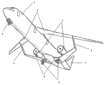
According to the invention, it is disclosed an aircraft comprising a fuselage
1, a propulsion system 5, a first pair of swept-back airfoils 2, connected to
the
top forward portion of the fuselage 1, a second pair of swept-forward airfoils
3,
connected to the lower rear portion of the fuselage 1 at a point of the said
fuse-
lage 1 aft of the connection of the swept-back airfoils 2, and a third pair of
sub-
stantially vertical airfoils 4, the tips of the swept-forward airfoils 3 being
con-
nected to the lower side of the swept-back airfoils 2 at an intermediate point
of
the span of the said swept-back airfoils 2, by means of the substantially
vertical
airfoils 4, the swept-back airfoils 2 having a higher aspect ratio than that
of the
swept-forward airfoils 3, which makes the swept-back airfoils 2 have a reduced
induced drag without penalizing their weight, as their maximum bending moment
CA 02758220 2011-10-07
7 -
is reduced because of the structural support that the swept-forward airfoils 3
provide to the swept-back airfoils 2 through the vertical airfoils 4.
According to the invention, the swept-back airfoils 2 and the swept-
forward airfoils 3 have sweep angles such that provide a horizontal separation
between said swept-back airfoils 2 and swept-forward airfoils 3, this
separation
reducing the compressible drag in the aircraft flight at high speeds due to
the
aerodynamic interaction of the airfoils 2 and 3, which is also advantageous
for
stability and control in flight.
Also, the horizontal stagger of the swept-back airfoils 2 and swept-forward
airfoils 3 of the aircraft configuration according to the invention provides
suffi-
cient longitudinal stability and control to the aircraft without the need of a
hori-
zontal stabilizer, resulting in a reduction of the overall wetted area and,
there-
fore, in a lower friction drag.
Moreover, according to the lambda-box wing configuration aircraft of the
invention, the center of lift of the swept-back airfoils 2 is located forward
of the
center of gravity of the aircraft, the center of lift of the swept-forward
airfoils 3
being located behind the center of gravity of the aircraft, this configuration
help-
ing to provide static stability to the mentioned aircraft.
Besides, the aircraft having the wing configuration of the lambda-box type
of the invention comprises the propulsion system 5 located on the upper side
of
the swept-forward airfoils 3, in such a way that the noise radiated downwards
by
the exhaust gases of the propulsion system 5 intercepts the said swept-forward
airfoils 3, which act as noise shields reducing the perceived noise the ground
during the aircraft flight.
BRIEF DESCRIPTION OF DRAWINGS
The foregoing objects and many of the attendant advantages of this in-
vention will become more readily appreciated as the same becomes better un-
derstood by reference to the following detailed description when taken in con-
junction with the accompanying drawings, wherein:
CA 02758220 2011-10-07
8 -
Figure 1 shows a perspective view of an aircraft having a wing arrange-
ment defining a box or closed frame according to a preferred embodiment of the
invention.
Figure 2 shows a top view of an aircraft having a wing arrangement defin-
ing a box or closed frame according to a preferred embodiment of the
invention.
Figure 3 shows a side view of an aircraft having a wing arrangement de-
fining a box or closed frame according to a preferred embodiment of the
invention.
Figure 4 shows a front view of an aircraft having a wing arrangement de-
fining a box or closed frame according to a preferred embodiment of the inven-
tion.
Figure 5 represents a partial side view of an aircraft according to the pre-
ferred embodiment of the invention showing one of the engines of the
propulsion
system, the main landing gear and the internal structure of the swept-forward
wing.
Figure 6 shows a top view of an aircraft having a wing arrangement defin-
ing a box or closed frame according to another embodiment of the invention
that
comprises additional horizontal stabilizing surfaces connected to the fuselage
of
the said aircraft.
DETAILED DESCRIPTION OF THE INVENTION
According to a first aspect, the invention relates to an aircraft comprising:
a fuselage 1; a first pair of swept-back airfoils 2, connected to the top
forward
portion of the fuselage 1; a second pair of swept-forward airfoils 3,
connected to
the lower rear portion of the fuselage 1; a third pair of substantially
vertical air-
foils 4, connecting the outermost tip of the swept-forward airfoils 3 to an
interme-
diate point of the span of the swept-back pair of airfoils 2; a propulsion
system 5
connected to the pair of swept-forward airfoils 3; a landing gear system 6; at
least one substantially vertical airfoil 7 connected to the aft portion of the
fuse-
lage 1, which provides directional stability and control to the aircraft.
CA 02758220 2011-10-07
9
The tips of the swept-forward airfoils 3 are connected to the lower side of
the swept-back airfoils 2 at an intermediate point of the span of the said
swept-
back airfoils 2, by means of substantially vertical airfoils 4, acting as an
structural
joint of the swept-back airfoils 2 and the swept- forward airfoils 3, designed
for
transmitting loads / forces between the swept-back airfoils 2 and the swept-
forward airfoils 3, said airfoils 4 being designed to act as aerodynamic
fences or
winglets to the swept-forward airfoils 3 with the aim of reducing the strength
of
the aerodynamic vortices that are normally produced at the tip of airfoils, so
that
the induced aerodynamic drag of the said swept-forward airfoils 3 is reduced.
The swept-forward airfoils 3 provide aerodynamic forces in the upwards
direction during the cruise portion of the flight of the aircraft.
According to the invention, and as it can more clearly be seen in Figure 2,
the. swept-back airfoils 2 have a significantly higher aspect ratio, defined
to be
the square of the span divided by the wing area (the aspect ratio representing
how long and slender the wings are) than that of the swept-forward airfoils 3.
This makes the swept-back airfoils 2 very efficient aerodynamically as their
in-
duced drag is much lower than that of a classical airfoil having an aspect
ratio in
the order of ten, without penalizing their weight as their maximum bending mo-
ment is reduced very significantly owing to the structural support that the
swept-
forward airfoils 3 provide to the slender swept-back airfoils 2 through the
vertical
airfoils 4. The swept-forward airfoils 3 are designed to be structurally
efficient in
order to provide bending support to the swept-back airfoils 2 and also to with-
stand the loads introduced by the propulsion system 5 and by the main part of
the landing gear system 6 located in the lower side of said swept-forward
airfoils
3. The structural efficiency of the swept-forward airfoils 3 is achieved by
having
relatively thick airfoils, so that the internal loads in the load bearing
skins are re-
duced, which leads to long chords or airfoil lengths and, therefore, to a
reduced
aspect ratio. The reduced aspect ratio of the swept-forward airfoils 3 would
nor-
mally lead to high induced aerodynamic drag if the tips of the airfoils were
free,
but in the present invention, the vertical airfoils 4 act as an aerodynamic
fence,
separating the upper and lower surfaces of the swept-forward airfoils 3 and
thus
reducing the strength of the tip vortex and the associated induced drag.
CA 02758220 2011-10-07
- 10 -
The high aspect ratio of the swept-back airfoils 2 and the use of the air-
foils 4 as aerodynamic fences for the swept-forward airfoils 3 result in a
reduced
overall induced drag of the aircraft having the wing configuration of the
present
invention. Additionally, the fact that in a preferred embodiment of the
present
invention there are no additional horizontal stabilizing surfaces as the
horizontal
stagger of the pairs of airfoils 2 and 3 provides sufficient longitudinal
stability and
control, results in a reduction of the overall wetted area in comparison with
the
classical configuration and, therefore, in a lower friction drag. The sweep
angles
of the pairs of airfoils 2 and 3, as well as providing the separation between
air-
foils required for stability and control are also beneficial for the flight at
high
speed, close to the speed of sound. Therefore, it can be said that the
aircraft
having the wing configuration of the present invention, called lambda-box con-
figuration because of the planform of the said wing configuration, similar to
that
of a lambda symbol, achieves an overall reduction of aerodynamic drag.
In the present invention, if the aircraft, flying in a trimmed and steady con-
dition, is subjected to a pitch-up perturbation in angle of attack as may be
caused by encountering a gust in flight, the increase in lift in the swept-
forward
airfoils 3 will be greater than in the swept-back airfoils 2 so that the
resulting
pitching moment will tend to lower the nose of the aircraft, this being the
main
condition for static stability. The above argument requires than the center of
lift
of the swept-back airfoils 2 is located forward of the center of gravity of
the air-
craft and that the center of lift of the swept-forward airfoils 3 is located
behind
the center of gravity of the aircraft and this is achieved in the present
invention
by the geometric arrangement of the airfoils in terms of their sweep angles
and
the location of their attachments to the fuselage 1. It can be seen then, that
with
both pairs of airfoils 2, 3 providing positive lift and arranged in such a
manner as
to provide natural static stability, there is no need to have an additional
horizon-
tal stabilizer.
The pitch control and trim of the aircraft is obtained by the deflection in
the adequate direction of control surfaces 10 on the swept-back airfoils 2
located
at the inboard portion of said swept-back airfoils 2 and adjacent to the
fuselage
1, these control surfaces 10 being able to deflect downwards in order to
produce
CA 02758220 2011-10-07
- 11 -
a pitch-up moment during the take-off run to assist the aircraft rotation for
lift-off,
and of control surfaces 9 located at the inboard portion of the swept-forward
air-
foils 3 adjacent to the fuselage 1, these control surfaces 9 being able to
deflect
upwards in order to produce a pitch-up moment during the take-off run to
assist
the aircraft rotation for lift-off. Thus, in order to produce the rotation of
the aircraft
during the take-off run, the control surfaces 10 have to deflect downwards and
the control surfaces 9 have to deflect upwards. From the above discussion, it
is
clear that in a preferred embodiment of the present invention there is no need
of
having an additional horizontal stabilizer that does not contribute to the
lift but
that is required in the classical configuration to provide stability.
Therefore, the
overall wetted area of the aircraft having the lambda-box wing configuration
of
the present invention can be reduced, with an associated reduction of the
friction
drag and thus an improvement of the fuel efficiency.
In another embodiment of the present invention, the aircraft can addition-
ally comprise a substantially horizontal pair of airfoils 14 located in the
aft portion
of the fuselage 1, these airfoils 14 being able to deflect around an axis
perpen-
dicular to the plane of symmetry of the aircraft to provide pitch control to
the said
aircraft, this configuration being suitable for the case in which, with the
preferred
embodiment of the invention, additional stability or control is required.
In yet another embodiment of the present invention, the aircraft can addi-
tionally comprise a substantially horizontal pair of airfoils 15 located in
the for-
ward portion of the fuselage 1, these airfoils 15 being able to deflect around
an
axis perpendicular to the plane of symmetry of the aircraft to provide pitch
con-
trol to the said aircraft, this configuration being suitable for the case in
which,
with the preferred embodiment of the invention, additional stability or
control is
required.
The roll or lateral control of the aircraft at low speeds is provided by trail-
ing edge control surfaces 8 being installed on the outer portion of the swept-
back
airfoils 2.
The propulsion system 5 of the aircraft typically comprises at least two
engines 5 of the turbojet, turbofan, turboprop or unducted fan type, said
engines
5 being structurally connected to the upper side of the swept-forward airfoils
3,
CA 02758220 2011-10-07
- 12 -
and being located in such a manner that the said swept-forward airfoils 3 act
as
noise shields to reduce the perceived noise produced by the exhaust gases of
said engines 5 on the ground during the aircraft flight. This perceived noise
re-
duction or noise shielding is achieved when the downwards portion of the noise
radiation of the exhaust gases generated by the engines 5 emitted at an angle
20 between 30 and 75 degrees, this angle 20 being measured from the axis of
symmetry of the exhaust jet, is intercepted by the upper side of the swept-
forward airfoils 3, which act as noise shields in this case.
The substantially vertical airfoil 7, located at the rear of the fuselage 1,
acts as a fin in order to provide directional stability and control to the
aircraft.
The landing gear system 6 comprises at least one leg connected to the
lower portion of the forward fuselage 1, and two legs connected to the lower
side
of the swept-forward airfoils 3 (Figure 1). The at least two legs of the lower
side
of the swept-forward airfoils 3 of the landing gear system 6 and the engines 5
are connected to the same structural spar 11 of the swept-forward airfoils 3,
so
that the inertial loads introduced by the engines 5 in cases of landing with
high
vertical accelerations are transmitted to the at least two legs of the landing
gear
system 6 and thereof to the ground through the shortest possible load path
within the airframe as it is allowed by landing gear legs separation and
engine
installation requirements.
Owing to the location of the propulsive system 5 over the swept-forward
airfoils 3, low ground clearance, or distance from the lower side of the
fuselage 1
to the ground, can be achieved, allowing therefore the installation of engines
of
large diameter without requiring long and heavy legs of the landing gear
system
6. This low ground clearance and the lack of horizontal stabilizing surfaces
at the
rear of the fuselage 1 make the aircraft lambda-box wing configuration of the
present invention particularly suited to the installation of a retractable
staircase
16 at the rear lower portion of the fuselage I (Figure 3) to allow direct
access of
the passengers to the interior of the aircraft without the need for additional
ground equipment.
Although the present invention has been fully described in connection
with preferred embodiments, it is evident that modifications may be introduced
CA 02758220 2011-10-07
13 -
within the scope thereof, not considering this as limited by these
embodiments,
but by the contents of the following claims.