Language selection

Search

Patent 2758408 Summary

Third-party information liability

Some of the information on this Web page has been provided by external sources. The Government of Canada is not responsible for the accuracy, reliability or currency of the information supplied by external sources. Users wishing to rely upon this information should consult directly with the source of the information. Content provided by external sources is not subject to official languages, privacy and accessibility requirements.

Claims and Abstract availability

Any discrepancies in the text and image of the Claims and Abstract are due to differing posting times. Text of the Claims and Abstract are posted:

  • At the time the application is open to public inspection;
  • At the time of issue of the patent (grant).
(12) Patent: (11) CA 2758408
(54) English Title: PERFORATED AIR-DUCT FOR GRAINS DRYING TOWER
(54) French Title: CONDUIT D'AIR PERFORE DESTINE A UNE TOUR DE SECHAGE DU GRAIN
Status: Granted
Bibliographic Data
(51) International Patent Classification (IPC):
  • A01F 25/12 (2006.01)
(72) Inventors :
  • PACHECO DA CUNHA, OTALICIO (Brazil)
(73) Owners :
  • PACHECO DA CUNHA, OTALICIO (Brazil)
(71) Applicants :
  • PACHECO DA CUNHA, OTALICIO (Brazil)
(74) Agent: RICHES, MCKENZIE & HERBERT LLP
(74) Associate agent:
(45) Issued: 2018-06-12
(86) PCT Filing Date: 2010-04-15
(87) Open to Public Inspection: 2010-10-21
Examination requested: 2015-04-10
Availability of licence: N/A
(25) Language of filing: English

Patent Cooperation Treaty (PCT): Yes
(86) PCT Filing Number: PCT/BR2010/000130
(87) International Publication Number: WO2010/118496
(85) National Entry: 2011-10-12

(30) Application Priority Data:
Application No. Country/Territory Date
PI0901256-7 Brazil 2009-04-16

Abstracts

English Abstract


PERFORATED AIR-DUCT FOR GRAINS DRYING TOWER, referring to a
trough (1) in V form, made-up by two vertical lateral faces (2), united by two

converging superior faces (3), the faces being provided with a multiplicity of

openings (5), which reduce the grains column between the trough layers (1)
in the tower, which increases the drying speed because the grains thickness
is finer, consequently reducing the drying time.


French Abstract

L'invention concerne une goulotte (1) en forme de V constituée par deux faces latérales verticales (2) jointes par deux faces supérieures convergentes (3), lesquelles sont pourvues d'une pluralité d'ouvertures (5) permettant de réduire la colonne de grains entre les rangées de goulottes (1) dans la tour, la vitesse de séchage augmentant du fait de l'épaisseur de grains réduite, d'où une réduction importante du temps de séchage.

Claims

Note: Claims are shown in the official language in which they were submitted.

We Claim:
1. A grain drying
tower comprising: a first vertical sidewall; a second
vertical sidewall opposite the first vertical sidewall; and a plurality of
perforated air ducts positioned within the grain drying tower extending
horizontally between the first vertical sidewall and the second vertical
sidewall
and having an elongate trough (1) in V form made-up by two vertical lateral
faces (2) united by two converging superior faces (3), characterized by a
multiplicity of perforation openings (5) being formed through each of the
vertical lateral faces and the converging superior faces (3); wherein each of
the plurality of perforated air ducts includes: a first end at the first
vertical
sidewall that is either blocked to form a blocked end or open to form an entry

end; and an opposite second end at the second vertical sidewall that is open
to form an exit end if the first end is a blocked end and is blocked to form a

blocked end if the first end is an open entry end; wherein rows are formed of
a
plurality of the perforated air ducts having approximately equal lateral
lengths
positioned such that positioned such that the lateral lengths are in parallel
spaced alignment in a horizontal plane with one another, and the first and
second ends are aligned in vertical planes with one another at the first and
second vertical sidewalls; wherein the rows of perforated air ducts are
vertically stacked within the grain drying tower; wherein the vertically
stacked
rows of perforated air ducts are positioned in an alternating staggered
alignment such that the horizontal perforated air duct of a row is offset from

adjacent perforated air ducts above and below it from vertically adjacent rows

and is positioned between the perforated air ducts of the vertically adjacent
row; wherein the plurality of perforated air ducts in a row are arranged in
the
row, and the rows are aligned vertically in the tower, to form at the second
ends of the perforated air ducts a pattern of exit ends that are horizontally
and
vertically next to blocked ends of adjacent perforated air ducts; wherein air
flows into the open entry ends at the first end of the plurality of perforated
air
ducts, continues through a portion of grain stored in the grain dryer tower,
and
flows out the open exit ends of the perforated air ducts thereby drying the
grain.
6

2. The grain drying
tower of claim 1 wherein the plurality of perforated air
ducts are arranged in each row, and the rows are aligned vertically in the
tower, to form at the first ends of the perforated air ducts a pattern of
inlet
ends that are horizontally and vertically next to the blocked ends of adjacent

perforated air ducts.
7

Description

Note: Descriptions are shown in the official language in which they were submitted.


CA 02758408 2016-09-29
PERFORATED AIR-DUCT FOR GRAINS DRYING TOWER
Invention technological sector
The grains drying after the harvest and before the storage is a need due
to the strongly hydrated by heaps product's characteristic alterations, such
as
the respiration or oxidation of glycides, intra-cellular fermentations,
development of bacteria and fungi, and all noxious effects resulting from.
The present invention belongs, in general way, to the technological
sector of grains drying equipments, and, more specifically, refers to a new
conception applied to an air-duct for drying towers.
Known state of technique
From the state of technique of this technological sector is known a
series of modalities of grain driers: the horizontal fixed layer driers, in
which
the product remains static in a compartment with perforated floor, through
which the heated air is blown; column driers, in which the product,
distributed
in vertical columns of perforated plates, is submitted to air flows
perpendicularly to the columns; concurrent flows driers, in which the grains
and the air flow in the same direction; counter-current flow driers, in which
the
grains and the air are moved in opposite directions; grains static driers,
which
blow hot air in troughs of V form, through which the grains to be dried pass.
Grains drying towers in static driers are provided of air entry and exit
ducts, known as troughs, through which the air flow is feed at one end, flows
along the air-duct, and exists through the longitudinal opening on the base,
passing through the grains mass, continuing in direction of other troughs in
parallel. This air is used to hear or cool, and, consequently, dry the grains
that
pass through the drying tower, as described in the document PI 0.802.885-0,
high performance grains drier, of the same demander of the present request.
This previous process describes a drier that conjugates in its drying
tower three air flow principles adopted in the drying processes (concurrent,
counter-current, and crossed), besides presenting different air flow values
from the top of the tower to its base, taking in consideration the grains
nature
and their behavior during the drying to obtain the process maximum efficiency,
1

CA 02758408 2016-09-29
and incorporation as well means for the grains loading box homogenizing,
hydraulic unloading, and hot air homogenizing.
Novelty and objectives of the invention
The present invention was conceived for the use in grains high
performance driers, but can also be used in other conventional driers.
The invention proposes the perforation of the troughs on their faces in
order to reduce the grains column between the trough layers, which increases
the drying speed because the grains thickness is finer, consequently reducing
the drying time. In this way, in the same static capacity, the production will
be
increased up to 100% in comparison to a drier of the same technology.
It is the case of a simple solution that provides a surprisingly new
technical effect.
Accordingly in one aspect the present invention resides in a grain
drying tower comprising: a first vertical sidewall; a second vertical sidewall
opposite the first vertical sidewall; and a plurality of perforated air ducts
positioned within the grain drying tower extending horizontally between the
first vertical sidewall and the second vertical sidewall and having an
elongate
trough in V form made-up by two vertical lateral faces united by two
converging superior faces, characterized by a multiplicity of perforation
openings being formed through at least either the vertical lateral faces or
the
converging superior faces; wherein each of the plurality of perforated air
ducts
includes: a first end at the first vertical sidewall that is either blocked to
form a
blocked end or open to form an entry end; and an opposite second end at the
second vertical sidewall that is open to form an exit end if the first end is
a
blocked end and is blocked to form a blocked end if the first end is an open
entry end; wherein rows are formed of a plurality of the perforated air ducts
having approximately equal lateral lengths positioned such that positioned
such that the lateral lengths are in parallel spaced alignment in a horizontal

plane with one another, and the first and second ends are aligned in vertical
planes with one another at the first and second vertical sidewalls; wherein
the
rows of perforated air ducts are vertically stacked within the grain drying
2

CA 02758408 2016-09-29
tower; wherein the vertically stacked rows of perforated air ducts are
positioned in an alternating staggered alignment such that the horizontal
perforated air duct of a row is offset from adjacent perforated air ducts
above
and below it from vertically adjacent rows and is positioned between the
perforated air ducts of the vertically adjacent row; wherein the plurality of
perforated air ducts in a row are arranged in the row, and the rows are
aligned
vertically in the tower, to form at the second ends of the perforated air
ducts a
pattern of exit ends that are horizontally and vertically next to blocked ends
of
adjacent perforated air ducts; wherein air flows into the open entry ends at
the
first end of the plurality of perforated air ducts, continues through a
portion of
grain stored in the grain dryer tower, and flows out the open exit ends of the

perforated air ducts thereby drying the grain.
Description of the annexed drawing
So that the present invention will be fully understood and taken to
practice by any technician in this technological sector, the same will be
explained in a clear, concise, and sufficient form to enable its reproduction,

having as basis the annexed drawings listed herein below, which illustrate and

subsidize the same.
Figure 1: Drawing in perspective of a concretization of the proposed
trough, object of the present invention, in which can be seen the openings on
its faces, and where the same is operating at the air entrance on the drier.
Figure 2: Drawing in perspective of a concretization of the proposed trough,
object of the present invention, in which can be seen the openings on its
faces
and the same is operating at the air exit on the drier.
Figure 3: Drawing in perspective of a second concretization of the
proposed trough, object of the present invention, in which can be seen
openings just on its superior faces, and the same was represented operating
at the air entry and exit on the drier.
Figure 4: Drawings in cut of the first concretization of the invention, on
which are represented the air entry and the corresponding hot air flow, and
the air exit, and the used air flow.
3

CA 02758408 2016-09-29
= =
Figure 5: Drawing in cut of the second concretization of the invention, in
which are represented the air entry and the corresponding hot air flow and the

air exit, and the used air flow.
Figure 6: Illustrative drawing in perspective of the troughs assembling in
the drier and of the corresponding air flows.
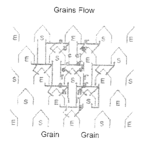
Figure 7: Schematic drawing of the troughs assembled in the drier and
of the related air flow directions, in which a= crosses to the left, b=
descending oblique, c= concurrent, d = crosses to the left, e = concurrent, f
=
counter-current, g = crosses to the right, h = descending oblique, I =
countercurrent, j = crosses to the right, a = crosses to the right, b =
counter-
current, c = concurrent, d = crosses to the left, e = descending oblique, f =
concurrent, g = crosses to the left, h = concurrent, I = counter-current, j =
crosses to the right.
Detailed description of the invention
As can be deduced in general from the annexed figures, the perforated
air-duct for grains drying towers, object of this descriptive report, refers
to a
trough (1) in V form, made-up by two vertical lateral faces (2), united by two

converging superior faces (3), and closed on one end (4), the faces being
provided of a multiplicity of openings (5), which reduce the grains column
between the trough layers (1) in the tower (figures 6 and 7), which increases
the drying speed because the grains thickness is finer, consequently reducing
the drying time.
One first concretization of the invention is represented in figures 1 and
2, presenting openings (5) on all peripheral faces. The air flow in the
troughs,
whenever operating as air entry (E) or air exit (S) is represented in figure
4.
A second concretization of the invention is represented in figure 3,
presenting opening (5) just on the converging superior faces. The air flow in
the troughs, when operating as air entry (E) or air exit (S) is represented in

figure 5.
4

CA 02758408 2016-09-29
Now just referring to figures 6 and 7, we see the effect enabled in the
troughs (1) by the openings (5) and the air flow in the troughs on a grains
drier.
The present descriptive report deals about an invention viewed for
industrial application, presenting novelty and inventive activity, provided of
all
requirements determined by the law to receive the requested privilege.
5

Representative Drawing
A single figure which represents the drawing illustrating the invention.
Administrative Status

For a clearer understanding of the status of the application/patent presented on this page, the site Disclaimer , as well as the definitions for Patent , Administrative Status , Maintenance Fee  and Payment History  should be consulted.

Administrative Status

Title Date
Forecasted Issue Date 2018-06-12
(86) PCT Filing Date 2010-04-15
(87) PCT Publication Date 2010-10-21
(85) National Entry 2011-10-12
Examination Requested 2015-04-10
(45) Issued 2018-06-12

Abandonment History

There is no abandonment history.

Maintenance Fee

Last Payment of $347.00 was received on 2024-04-09


 Upcoming maintenance fee amounts

Description Date Amount
Next Payment if standard fee 2025-04-15 $624.00
Next Payment if small entity fee 2025-04-15 $253.00

Note : If the full payment has not been received on or before the date indicated, a further fee may be required which may be one of the following

  • the reinstatement fee;
  • the late payment fee; or
  • additional fee to reverse deemed expiry.

Patent fees are adjusted on the 1st of January every year. The amounts above are the current amounts if received by December 31 of the current year.
Please refer to the CIPO Patent Fees web page to see all current fee amounts.

Payment History

Fee Type Anniversary Year Due Date Amount Paid Paid Date
Application Fee $400.00 2011-10-12
Maintenance Fee - Application - New Act 2 2012-04-16 $100.00 2012-03-27
Maintenance Fee - Application - New Act 3 2013-04-15 $100.00 2013-04-11
Maintenance Fee - Application - New Act 4 2014-04-15 $100.00 2014-03-27
Maintenance Fee - Application - New Act 5 2015-04-15 $200.00 2015-03-31
Request for Examination $800.00 2015-04-10
Maintenance Fee - Application - New Act 6 2016-04-15 $200.00 2016-03-30
Maintenance Fee - Application - New Act 7 2017-04-18 $200.00 2017-04-07
Maintenance Fee - Application - New Act 8 2018-04-16 $200.00 2018-03-27
Final Fee $300.00 2018-04-24
Maintenance Fee - Patent - New Act 9 2019-04-15 $200.00 2019-04-03
Maintenance Fee - Patent - New Act 10 2020-04-15 $250.00 2020-04-01
Maintenance Fee - Patent - New Act 11 2021-04-15 $255.00 2021-04-13
Maintenance Fee - Patent - New Act 12 2022-04-19 $254.49 2022-03-22
Maintenance Fee - Patent - New Act 13 2023-04-17 $263.14 2023-04-11
Maintenance Fee - Patent - New Act 14 2024-04-15 $347.00 2024-04-09
Owners on Record

Note: Records showing the ownership history in alphabetical order.

Current Owners on Record
PACHECO DA CUNHA, OTALICIO
Past Owners on Record
None
Past Owners that do not appear in the "Owners on Record" listing will appear in other documentation within the application.
Documents

To view selected files, please enter reCAPTCHA code :


To view images, click a link in the Document Description column. To download the documents, select one or more checkboxes in the first column and then click the "Download Selected in PDF format (Zip Archive)" or the "Download Selected as Single PDF" button.

List of published and non-published patent-specific documents on the CPD .

If you have any difficulty accessing content, you can call the Client Service Centre at 1-866-997-1936 or send them an e-mail at CIPO Client Service Centre.


Document
Description 
Date
(yyyy-mm-dd) 
Number of pages   Size of Image (KB) 
Maintenance Fee Payment 2021-04-13 1 33
Maintenance Fee Payment 2023-04-11 1 33
Abstract 2011-10-12 1 11
Claims 2011-10-12 1 15
Description 2011-10-12 4 142
Cover Page 2011-12-15 1 28
Drawings 2011-10-12 5 93
Claims 2015-09-21 2 65
Description 2015-09-21 5 191
Description 2016-09-29 5 194
Claims 2016-09-29 2 67
Amendment 2017-07-24 7 247
Claims 2017-07-24 2 54
Office Letter 2017-10-25 2 66
Maintenance Fee Payment 2018-03-27 1 52
Final Fee / Response to section 37 2018-04-24 1 59
Abstract 2018-05-04 1 11
Representative Drawing 2018-05-23 1 15
Cover Page 2018-05-23 1 42
PCT 2011-10-12 8 360
Assignment 2011-10-12 3 112
Fees 2012-03-27 1 52
Fees 2013-04-11 1 53
Fees 2014-03-27 1 53
Fees 2015-03-31 1 52
Prosecution-Amendment 2015-04-10 1 55
Amendment 2015-09-21 7 230
Examiner Requisition 2016-03-29 5 289
Maintenance Fee Payment 2016-03-30 1 50
Amendment 2016-09-29 12 437
Examiner Requisition 2017-01-23 4 256
Maintenance Fee Payment 2017-04-07 1 51