Note: Descriptions are shown in the official language in which they were submitted.
CA 02758517 2016-07-26
1
SHOCK ABSORBER HAVING UNIDIRECTIONAL FLUID
FLOW
CROSS REFERENCE TO RELATED APPLICATION
[0001] This application claims the benefit of U.S. Provisional Application
61/169,843, which was filed on April 16, 2009.
BACKGROUND OF THE INVENTION
1. Field of the Invention
[0002] The present invention pertains to a shock absorber. More
particularly, the present invention pertains to a shock absorber having a twin
tube construction. Even more particularly, the present invention pertains to a
twin tube construction shock absorber having unidirectional fluid flow.
2. Description of the Prior Art
[0003] Shock absorbers are well known in the art, such as found in U.S.
Patent Nos. 2,804,513 to Oppel; 5,588,510 to Wilke; 6,648,109 to Farr et al.;
6,913,126 to Dohrmann et al.; as well as U.S. Patent Publication No.
2002/0121416 to Katayama et al. The shock absorbers disclosed by Oppel, Wilke,
Farr, Dohrmann, and Katayama are representative of the types of shock
absorbers that are commonly available. Such shock absorbers generally
comprise a cylinder and a piston, the piston being connected to a rod which
experiences a load. Fluid is contained within the cylinder. As the piston
experiences compression and rebound strokes, fluid is forced out of one side
of
the cylinder and fluid is forced into the other side through a series of
valves. The
CA 02758517 2011-10-12
WO 2010/121108 PCT/US2010/031360
2
valves may be disposed on the external portion of the shock absorber. The
shock
absorber may also provide additional external components for controlling the
flow of fluid from one side of the cylinder to the other, thereby controlling
the
damping force of the shock absorber.
[0004] However, such existing designs require a series of complex valve
components which can be expensive, difficult to maintain, and difficult to
assemble. In addition, shock absorbers using this construction rely upon a
series
of valves to control the variability of the damping. Therefore, it is
difficult to
variably adjust the damping rate for these shock absorbers.
[0005] Thus, there remains a need for a shock absorber which has a
simpler construction, requires less moving parts, allows for easy adjustment
of
the damping force, and which preferably requires the same or less room than
shock absorbers which are found in the prior art.
[0006] The present invention, as is detailed hereinbelow, seeks to
resolve
these issues by providing a twin-tube construction shock absorber which has
unidirectional fluid flow throughout the system and which comprises a minimal
number of moving parts, and which may additionally have the damping force
adjusted easily and/or remotely.
SUMMARY OF THE INVENTION
[0007] In a first embodiment hereof, the present invention provides a
unidirectional twin-tube shock absorber which generally comprises:
(a) a cylindrically elongated outer tube having a first end and a
second
end;
CA 02758517 2011-10-12
WO 2010/121108 PCT/US2010/031360
3
(b) a cylindrically elongated inner tube housed within the outer tube,
the inner tube having an interior surface, a first end, and a second end which
define an interior volume, the inner tube forming an annulus area between the
outer tube and the inner tube, the inner tube having a check valve which
allows
a fluid to flow unidirectionally from the annulus area to the interior volume
of
the inner tube;
(c) a piston slidably disposed within the inner tube, the piston having
an outer circumferential surface dimensioned to form a barrier against the
interior surface of the inner tube, the piston dividing the interior volume
into a
rod side chamber and a cap side chamber, the piston having a piston check
valve
which allows the fluid to flow unidirectionally from the cap side chamber to
the
rod side chamber;
(d) a piston rod secured to the piston and extending outwardly past the
first end of the outer tube; and
(e) a flow regulator secured to the inner tube which allows
unidirectional flow of the fluid from the rod side chamber to the annulus
area,
wherein the flow regulator provides a resistance against the flow of the fluid
from the rod side chamber to the annulus area.
[0008] The flow regulator can comprise a valve seat and a spring disk for
directing the flow of the first fluid from the rod side chamber to the annulus
area. The valve seat is generally disk-like in shape and has a generally
circular
outer circumferential edge and a central circular opening. The valve seat is
preferably disposed about the first end of the inner tube and has the piston
rod
extending through the central circular opening. The valve seat comprises a
CA 02758517 2011-10-12
WO 2010/121108 PCT/US2010/031360
4
plurality of orifice holes disposed about the valve seat, the orifice holes
being in
fluid communication with the rod side chamber.
[0009] The spring disk can be provided for regulating the flow of the
first
fluid from the orifice holes to the annulus area. The spring disk is generally
disk-like in shape and has an inner circumferential edge defining a central
circular opening through which the piston rod extends. The spring disk also
has
an outer circumferential edge. The spring disk is positioned over the valve
seat
and secured to the valve seat along the inner circumferential edge, wherein
pressure from the fluid flowing through the orifice holes upwardly deflects
the
outer circumferential edge of the spring disk allowing the fluid to flow into
the
annulus area.
[0010] The present invention can optionally include a piston rod
intrusion
makeup area to compensate for volume taken up by the piston rod within the rod
side chamber of the inner tube during compression. The piston rod intrusion
makeup area comprises a portion of the annulus area which is filled with a
compressible fluid, the compressible fluid preferably being a gaseous fluid,
such
as air or other gas. Alternatively, the intrusion makeup area may comprise a
cylinder, which is housed either internally or externally of the outer tube,
and
which is in fluid communication with the annulus area.
[0011] The intrusion makeup area operates to compensate for the
additional volume consumed by the piston rod during a compression stroke. As
the piston rod enters the inner tube during a compression stroke, a volume of
the
fluid is displaced out of the inner tube by the piston rod, and into the
annulus
area. The intrusion makeup area compensates for this additional displacement
CA 02758517 2011-10-12
WO 2010/121108 PCT/US2010/031360
by providing the compressible fluid which is compressed under pressure from
the
fluid. As the compressible fluid is compressed, it decreases in volume,
thereby
creating space for the increase in volume of the fluid in the annulus area.
[0012] For a more complete understanding of the present invention,
reference is made to the following detailed description and accompanying
drawing. In the drawing, like reference characters refer to like parts
throughout
the views in which:
BRIEF DESCRIPTION OF THE DRAWINGS
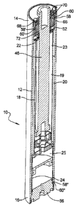
[0013] FIG. 1 is a perspective view in cross-section of a first
embodiment of
the present invention hereof;
[0014] FIG. 2 is an enlarged perspective view in cross-section of the
second
end of the present invention;
[0015] FIG. 3 is an enlarged perspective view in cross-section of the
first
end of the present invention;
[0016] FIG. 4 is an enlarged sectional view of the valve seat and spring
disk assembly according to the present invention;
[0017] FIG. 5 is an enlarged section view wherein the flow regulator
comprises a valve seat, a pre-load seat, and an electromagnet;
[0018] FIG. 6 is an enlarged section view wherein the flow regulator
comprises a valve seat and a turbine; and
[0019] FIG. 7 is an enlarged cutaway sectional view showing the turbine
armature and a plurality of coil carriers.
CA 02758517 2011-10-12
WO 2010/121108 PCT/US2010/031360
6
DETAILED DESCRIPTION OF THE PREFERRED EMBODIMENTS
[0020] In accordance with a first embodiment of the present invention and
as shown generally in FIGS. 1-4, there is provided a shock absorber 10 having
a
twin tube construction. The shock absorber 10 comprises a cylindrical
elongated
outer tube 12 having a first end 14 and a second end 16. Although the first
and
second ends, 14 and 16, are preferably open, the first and second ends, 14 and
16,
may be closed with a cap (not shown) after the internal components of the
shock
absorber 10 have been assembled therein. If cap ends are provided, they may be
secured to the outer tube 12 by means which are well known in the art, such as
by welding, crimping, threaded connection, or the like. The outer tube 12 is
formed from materials which are well known in the art for use with shock
absorbers, including but not limited to, carbon steel, aluminum, stainless
steel,
composite materials, or the like. Although not shown, the second end 16 of the
outer tube 12 preferably comprises means for securement to an object such as
an
axle or a vehicle frame.
[0021] The outer tube 12 houses on inner tube 18. The inner tube 18
comprises a cylindrical elongated tube 19 having a first open end 22, a second
open end 24, and an interior surface 23 which collectively define an interior
volume 25. The inner tube 18 and the outer tube 12 are preferably
substantially
coaxially parallel with each other and define an annulus area 20 therebetween.
The inner tube 18 is formed from materials which are well known in the art,
including but not limited to, carbon steel, stainless steel, composite
materials, or
the like.
CA 02758517 2011-10-12
WO 2010/121108 PCT/US2010/031360
7
[0022] The inner tube 18 and the annulus area 20 are filled with a fluid
30.
The fluid 30 may be either gaseous or liquid. Preferably, the fluid 30 is a
liquid
such as oil. The type of fluid used may be any suitable type which is well
known
in the art for use with shock absorbers.
[0023] As shown in FIG. 2, the inner tube 18 also comprises a check valve
26 located proximal to the second end 24 thereof. The check valve 26 places
the
annulus area 20 and the interior volume 25 of the inner tube 18 in fluid
communication, and allows the fluid 30 to flow from the annulus area 20 into a
cap side chamber 28 of the inner tube 18, as discussed in further detail
below.
Any suitable type of check valve which is well known in the art may be used,
including but not limited to, a ball and spring check valve, such as found in
U.S.
Patent No. 3,343,564 to Peeples et al., or a deflected disk check valve, such
as
found in U.S. Patent No. 2,223,944 to Roy. Preferably, a deflected disk check
valve is used because it has flow and pressure drop characteristics which are
desirable for application in the present invention.
[0024] As seen in FIG. 3, the inner tube 18 houses a piston 32. The
piston
32 is generally disk-like in shape and has an outer circumferential surface
34.
The piston 32 is dimensioned such that the outer circumferential surface 34 of
the piston 32 is juxtaposed the inner surface 23 of the inner tube 18, thereby
forming a substantially fluid-tight barrier between the inner tube 18 and the
piston 32. The piston 32 is capable of sliding to and fro along an axis of the
inner
tube 18, and divides the interior volume of the inner tube 18 into two
separate
chambers, namely, a rod side chamber 38 and a cap side chamber 28.
CA 02758517 2011-10-12
WO 2010/121108 PCT/US2010/031360
8
[0025] The outer circumferential surface 34 of the piston 32 may include
a
recess 40 extending thereabout for housing a seal 42, such as an 0-ring or any
other suitable type of seal. The seal 42 assists in forming the barrier
between
the piston 32 and the inner tube 18. The seal 42 also acts as a bearing
between
the inner tube 18 and the piston 32. The seal 42 is formed from materials
which
are well known in the art, including but not limited to, polymers such as
plastics
or elastomers.
[0026] The piston 32 additionally comprises a check valve 44. The check
valve 44 is of similar type as discussed above, and may be placed atop the
piston
32 or retained within the piston 32. The piston check valve 44 places the cap
side chamber 28 and the rod side chamber 38 in fluid communication, such that
the fluid 30 may flow from the cap side chamber 28, through the piston check
valve 44, and into the rod side chamber 38.
[0027] A piston rod 46 is provided which is secured to the piston 32. The
piston rod 46 is substantially coaxially aligned with the inner tube 18, and
extends outwardly from the piston 32 toward the first end 14 of the outer tube
12. The piston rod 46 extends through a central circular opening 48 of a valve
seat 50 and through a rod side seal carrier 52, which are discussed in further
detail below. The piston rod 46 has a distal end 54 which extends outwardly
past
the first end 14 of the outer tube 12. The distal end 54 of the piston rod 46
preferably includes means for securement (not shown) to an object (not shown),
such as an axle or frame of a vehicle. The means for securement may include
any suitable means which are well-known in the art, such as a bracket, clamp,
and so forth.
CA 02758517 2011-10-12
WO 2010/121108 PCT/US2010/031360
9
[0028]
Referring back to FIG. 1, the outer tube 12 houses the rod side seal
carrier 52 and a cap side seal carrier 56. Each of the seal carriers 52,56 is
located at its respective end of the outer tube 12. Each seal carrier 52,56 is
substantially cylindrical in shape and dimensioned to be insertable into the
outer
tube 12. The seal carriers 52,56, are provided to support and seal the
internal
components of the shock absorber 10. Each seal carrier 52,56 comprises a
plurality of seals 58,58',etc. for preventing fluid 30 from exiting the outer
tube
12. Each seal carrier, 52 and 56, has at least one annular recess 60,60',etc.
encircled about an outer circumferential surface 62,62', and at least one of
the
seals from the plurality of seals 58,58',etc. is disposed in each recess
60,60',etc. to
seal the surface interface between the seal carriers 52,56 and the outer tube
12.
[0029]
Each seal carrier 52,56 is formed from suitable materials which
are non-porous and have desirable temperature and strength characteristics
enabling them to last a long time, such as a metal (e.g. aluminum, brass,
steel,
etc.) or a polymer (e.g. nylon). Preferably the seal carriers 52,56 are made
from
steel.
[0030]
Furthermore, each seal carrier 52,56 is secured within its respective
end of the outer tube 12 by suitable means which are well known in the art.
For
instance, each seal carrier 52,56 may be press fit into the outer tube 12.
Additionally the outer circumferential surface 62,62' of each seal carrier
52,56
and the inner surface 64 of each end of the outer tube 12 may be threaded for
threaded interengagement with each other. As such, each seal carrier 52,56 may
be threadably secured within its respective end of the outer tube 12.
CA 02758517 2011-10-12
WO 2010/121108 PCT/US2010/031360
[0031] It is to be understood by one having ordinary skill in the art
that if
an outer tube 12 is provided which has a closed second end 16, then the cap
side
seal carrier 56 is not required in order to seal the outer tube 12.
[0032] As shown in FIGS. 1 and 3, the rod side seal carrier 52 also
comprises an inner circular through-hole 66 which is dimensioned to retain the
piston rod 46. The inner circular through-hole 66 comprises at least one
annular
recess 68 to retain a seal 70 for sealing the surface interface between the
rod side
seal carrier 52 and the piston rod 46. The seals 70 and 58,58',etc. used for
sealing the seal carriers 52,56 are formed from materials which are well known
in the art, including polymers such as plastics or elastomers.
[0033] In addition, the through-hole 66 of the rod side seal carrier 52
has a
bearing surface 72 for maintaining the piston rod 46 in alignment with the
inner
and outer tubes, 14 and 12, respectively. The bearing surface 72 is preferably
a
linear bearing of the type which is well-known in the art. Even more
preferably,
the linear bearing comprises a plane bearing having a bearing surface made of
polytetrafluoroethylene, which is commonly sold under the trademark Teflon .
Alternatively, the linear bearing may be a roller-type bearing having a
plurality
of recirculating ball bearings.
[0034] In use, the piston rod 46 is configured to be secured to a first
object
(not shown), such as the frame of a vehicle, and the outer tube 12 of the
shock
absorber 10 is configured to be secured to a second object (not shown), such
as
the axle of a vehicle. When the first and second objects move relative to each
other, the piston 32 and piston rod 46 move relative to the inner and outer
tubes
14,12 of the shock absorber 10. It is thus seen that the piston 32 and piston
rod
CA 02758517 2011-10-12
WO 2010/121108 PCT/US2010/031360
11
46 slidably move relative to the inner tube 18 during operation of the shock
absorber 10.
[0035] Referring back to the internal components of the shock absorber 10
as shown in FIG. 4, a flow regulator 49 is provided for directing the fluid 30
to
flow from the rod side chamber 38 to the annulus area 20. The flow regulator
49
can comprise a valve seat 50 and at least one spring disk 80. The valve seat
50 is
generally disk-like in shape and is secured about the first end 22 of the
inner
tube 18. The valve seat 50 has a central circular opening 48 through which the
piston rod 46 extends. The valve seat 50 comprises a plurality of orifice
holes
76,76',etc. The orifice holes 76,76',etc. extend through the valve seat 50
such
that the rod side chamber 38 of the inner tube 18 is placed in fluid
communication with the area atop the valve seat 50. The orifice holes
76,76',etc.
are disposed about the valve seat 50, preferably in an evenly-spaced array.
The
valve seat 50 further comprises a raised ridge, or land seat 78, which extends
about the outermost circumferential edge of the valve seat 50. The land seat
78
can include notches for bleeding a minimal flow of fluid 30 past the valve
seat 50,
as will be better understood by the following discussion.
[0036] At least one spring disk 80 can be provided for regulating the
flow of
fluid 30 through the orifice holes 76,76',etc. and into the annulus area 20.
The at
least one spring disk 80 comprises a generally circular disk which is
substantially planar or flat and is capable of being deflected. The spring
disk 80
has an outer edge 82, a central circular opening 84, and an inner edge 86. The
inner edge 86 encircles the piston rod 46. The spring disk 80 is positioned
over
the valve seat 50 such as shown in FIG. 4. The inner edge 86 is secured to the
CA 02758517 2011-10-12
WO 2010/121108 PCT/US2010/031360
12
valve seat 50 in a manner which is described in further detail below. The
outer
edge 82 of the spring disk 80 sits atop, or abuts the land seat 78 of the
valve seat
50.
[0037] In operation, pressurized fluid 30 flows up through the orifice
holes
76, 76',etc. and applies an upward force against the bottom side of the spring
disk 80. The spring disk 80 is deflected about the secured inner edge 86,
thereby
creating a gap between the outer edge 82 of the spring disk 80 and the land
seat
78 through which the fluid 30 flows. The amount of pressure, or force,
required
to deflect the spring disk 80 (and allow the fluid 30 to flow) is commonly
known
in the art as the "blow off' pressure.
[0038] If more than one spring disk 80 is provided, then the plurality of
spring disks 80 may be stacked together. In such an arrangement, each spring
disk 80 from the plurality of spring disks 80 may have a consistent nominal
thickness, such that adjusting the number of spring disks used may be a
parameter employed for adjusting the blow off pressure.
[0039] The spring disk 80 is formed from any suitable material known in
the art, including metals such as spring steel, and in particular, blue
tempered
spring steel. It is understood to those having ordinary skill is in the art
that the
material used should have a high yield strength so that the spring disk 80
does
not experience plastic deformation. It is also understood by one of ordinary
skill
in the art that the type of material chosen for the spring disk 80, and its
corresponding material properties, such as elasticity and strength, are a
factor in
determining the amount of force generated for any given velocity.
CA 02758517 2011-10-12
WO 2010/121108 PCT/US2010/031360
13
[0040] As shown in FIG. 4, the inner edge of the spring disk 80 is
secured
between the rod side seal carrier 52 and the valve seat 50 by a plurality of
shims
88. At least one shim 88 can be positioned below and above the spring disk 80.
The shims 88 and the spring disk 80 are clamped tightly between the rod side
seal carrier 52 and the valve seat 50, thereby securing the inner edge 86 of
the
spring disk 80 in position. The quantity and thickness of the shims 88 used
determines the shim height, which is designated as x in FIG. 4. For any
particular spring disk thickness, as the shim height x decreases, the blow off
pressure increases. The shims 88 are formed from suitable materials well-
known in the art, including, carbon steel. It is to be appreciated by one
having
ordinary skill in the art that the shim height is one of several factors
relevant to
determining the blow off pressure. It is also to be understood by those having
ordinary skill in the art that assembling the spring disk 80 and shims 88 in a
manner which requires a force to deflect the spring disk 80 away from the land
seat 78 is referred to as "preloading."
[0041] The rod side seal carrier 52, valve seat 50, spring disk 80, and
shims 88 may be assembled together by a number of suitable methods.
Preferably, the valve seat 50 is placed into the outer tube 12 (sitting atop
the
inner tube 18), and at least one shim 88 is placed over the valve seat 50. The
spring disk 80 is then placed atop the at least one shim 88. At least one
additional shim 88 is then placed over the spring disk 80. The rod side seal
carrier 52 is then placed over the valve seat 50, spring disk 80, and shims
88.
The rod side seal carrier 52 is secured in position, thereby securing the
valve
seat 50, inner edge 86 of the spring disk 80, and shims 88 in position.
CA 02758517 2011-10-12
WO 2010/121108 PCT/US2010/031360
14
Alternatively, an assembly of the rod side seal carrier 52, shims 88, spring
disk
80, and valve seat 50 may be press fit together, and assembled into the shock
absorber 10 as an assembled unit.
[0042] In a further alternate method of assembly, the valve seat 50 and
rod
side seal carrier 52 may be provided with corresponding threaded surfaces such
that the shims 88 and spring disk 80 may be assembled onto the valve seat 50,
and the rod side seal carrier 52 and valve seat 50 may then be threadably
secured to each other. The entire threaded assembly may then be inserted into
the shock absorber 10. Otherwise, the threaded valve seat 50, shims 88, and
spring disk 80 may be inserted into the shock absorber 10 and the threaded rod
side seal carrier 52 may then be threadably secured to the threaded valve seat
50.
[0043] The present invention may also provide a piston rod intrusion
makeup area 90 to compensate for volume taken up by the piston rod 46 within
the inner tube 18 during a compression stroke. During a compression stroke,
the
piston rod 46 enters the inner tube 18, thereby taking up an increasing amount
of volume within the inner tube 18. Since the inner tube 18 has a finite
interior
volume, a piston rod intrusion makeup area 90 may be provided to compensate
for the increase in volume of the piston rod 46. The piston rod intrusion
makeup
area 90 contains a volume of compressible fluid 91 and is in fluid
communication
with the annulus area 20. Preferably the intrusion makeup area 90 is located
within the annulus area 20, however, it can be positioned in any other
suitable
location, even including outside the shock absorber 10 itself.
CA 02758517 2011-10-12
WO 2010/121108 PCT/US2010/031360
[0044] The
intrusion makeup area 90 can optionally include a fluid
separator 93 to isolate the fluid 30 and the compressible fluid 91 from mixing
with each other during operation. As understood by one of ordinary skill in
the
art, mixing of the two fluids is undesirable, particularly when the fluid 30
is a
liquid and the compressible fluid 91 is a gas. The fluid separator 93 can
comprise a flexible membrane (e.g., membrane formed from a flexible polymer
such as an elastomer), a floating physical barrier (e.g., a floating disc or
cylinder), or any other suitable means for isolating the fluids from each
other to
minimize or eliminate intermixing.
[0045] In
operation, as the piston rod 46 enters the inner tube 18, fluid 30
is displaced by the piston rod 46 and forced into the annulus area 20. As the
fluid 30 becomes pressurized, it compresses the compressible fluid 91 in the
intrusion makeup area 90, thereby allowing the fluid 30 to expand into a
portion
of the intrusion makeup area 90. The compressible fluid 91 housed in the
intrusion makeup area 90 may be air or a gas, such as nitrogen, xenon, or the
like. The compressible fluid 91 may be at atmospheric pressure or it may be
pressurized. Preferably, the compressible fluid 91 is either air (at either
atmospheric pressure or compressed) or compressed nitrogen. It may also be
possible that the compressible fluid 91 comprises a closed cell foam rather
than a
gaseous fluid in situations where aeration or cavitation occurs.
[0046] The
present invention can optionally provide means for diverting
fluid flow 94 from the valve seat 50 into the annulus area 20. The means for
diverting fluid flow 94 can be provided to assist the fluid flow from becoming
turbulent as it exits the valve seat 50. The means for diverting fluid flow 94
may
CA 02758517 2011-10-12
WO 2010/121108 PCT/US2010/031360
16
comprise a curved disk, a downwardly pointing vent, or any other suitable
means
which are well-known in the art. The flow of the fluid 30 is preferably
laminar
as it exits the valve seat 50 so that it does not become aerated or experience
cavitation.
[0047] In use, the shock absorber 10 is continuously experiencing
compression and rebound strokes. In a typical shock absorber, fluid moves in a
bidirectional flow back and forth from one side of the piston to the other, as
well
as in and out of a rod intrusion makeup area connected to the rod side
chamber.
However, in the present invention, the fluid 30 flows unidirectionally
regardless
of whether the shock absorber 10 is experiencing a compression or rebound
stroke, as discussed below.
[0048] According to the present invention, during a compression stroke
the
piston 32 is forced downward by the piston rod 46. The check valve 44 in the
piston 32 allows the fluid 30 to flow from the cap side chamber 28 to the rod
side
chamber 38. The inner tube check valve 26 does not allow the fluid 30 in the
cap
side chamber 28 to exit through the inner tube check valve 26. However, as the
piston rod 46 enters the inner tube 18, it consumes an increasing amount of
volume within the inner tube 18, thereby forcing that same volume of fluid 30
out of the rod side chamber 38, through the orifice holes 76,76',etc., past
the
spring disk 80, and into the intrusion makeup area 90. It is thus seen that
during the compression stroke, the force required to deflect the spring disk
80
and the force required to compress the compressible fluid 91 in the intrusion
makeup area 90 collectively provide a damping force to the piston rod 46.
CA 02758517 2011-10-12
WO 2010/121108 PCT/US2010/031360
17
[0049] During the rebound stroke, the piston 32 and the piston check
valve
44 force fluid 30 out of the rod side chamber 38, through the orifice holes
76,76',etc., past the deflected spring disk 80, and into the annulus area 20.
As
the piston rod 46 exits the inner tube 18, the piston rod 46 itself consumes
less
volume, and the fluid 30 exits the intrusion makeup area 90. As the fluid 30
is
forced into the annulus area 20, it flows through the inner tube check valve
26,
and into the cap side chamber 28 of the inner tube 18. It is noted that, since
the
fluid 30 is contained within a sealed system, the piston 32 also creates a
vacuum
in the cap side chamber 28 during rebound, thereby contemporaneously drawing
the fluid 30 into the cap side chamber 28. During rebound, the spring disk 80
provides the damping force to the shock absorber 10.
[0050] It is thus seen that, as the shock absorber 10 repetitively
experiences compression and rebound, the fluid 30 continues to flow up from
the
cap side chamber 28 to the rod side chamber 38, through the orifice holes
76,76',etc., past the deflected spring disk 80, into the annulus area 20,
through
the inner tube check valve 26, and once again into the cap side chamber 28 of
the
inner tube 18.
[0051] As shown in FIG. 5, in addition to the valve seat 50 and the
spring
disk 80, the flow regulator 49 can optionally include a pre-load seat 112
and/or
an actuator 114. The pre-load seat 112 is juxtaposed a top surface 92 of the
spring disk 80. The pre-load seat 112 is preferably generally circular in
shape.
Preferably, the pre-load seat 112 is secured to the spring disk 80, and can be
formed from a magnetic material. The pre-load seat 112 is concentrically
positioned over the spring disk 80 and may be dimensioned to contact the
spring
CA 02758517 2011-10-12
WO 2010/121108 PCT/US2010/031360
18
disk 80 at a particular radial length from the center point of the spring disk
80.
It is thus seen that by varying the radial contact position between the pre-
load
seat 112 and the spring disk 80, the mechanical advantage of the pre-load seat
112 over the spring disk 80 may by variably adjusted. Furthermore, the spring
disk 80 can optionally have an oversized diameter such that the outer
circumferential edge of the spring disk 80 may extend beyond the land seat 78,
and the pre-load seat 112 can be positioned over the spring disk 80 at a
radial
position outside the land seat 78, thereby giving the pre-load seat 112 a
further
mechanical advantage.
[0052] It is also appreciated that the radial position of the pre-load
seat
112 on the spring disk 80 is yet another factor which contributes to the
resulting
damping force of the shock absorber 10.
[0053] The actuator 114 can be provided for applying a force to the pre-
load
seat 112. The actuator 114 is preferably any suitable type of electro-
mechanical
device, such as the type including an electromagnet, for example, a solenoid.
The
actuator 114 is configured to receive electrical current from a source such as
a
battery or an alternator. Means for connecting 116 the actuator 114 to each
pre-
load seat 112 can be provided such that, by conducting electricity through the
actuator 114, the actuator 114 applies a force to the pre-load seat 112, which
in
turn, applies that force to the top surface 92 of the spring disk 80. The
means for
connecting 116 may comprise a rod, coil, spring, or the like. In addition, the
pre-
load seat 112 may be formed from a magnetic material, such that a magnetic
force may be applied to the pre-load seat 112 by the actuator 114. It is thus
seen
that, by varying the electrical current through an actuator 114, the resulting
CA 02758517 2011-10-12
WO 2010/121108 PCT/US2010/031360
19
force applied to the spring disk 80 is proportionately varied. It is noted
that the
force applied to the spring disk 80 by the actuator 114 can be either an
upward
or downward force. As such, the amount of force required to deflect the spring
disk 80 can be controlled by electro-mechanical means, so long as the spring
disk
80 remains secured to the actuator 114.
[0054] It is to be understood by one having ordinary skill in the art
that,
according to this arrangement, the blow off pressure is equal to the preload
force
of the spring disk 80 against the land seat 78 plus the amount of force
applied
onto the top surface 92 of the spring disk 80 by the actuator 114. Therefore,
in
such an embodiment, it may be possible to reduce the preload force of the
spring
disk 80 such that the blow off pressure is substantially equal to the amount
of
downward force applied by the actuator 114.
[0055] The means for connecting 116 can also apply an upward force on the
spring disk 90. As such, the actuator 114 and means for connecting 116 can be
configured to decrease the blow off pressure when the electromagnetic 114
applies an upward force to reduce the damping force for effectively creating a
.`negative" blow off pressure. The means for connecting 116 can compromise any
suitable component well-known in the art, such as a rod or other suitable
member secured to the actuator 114 and the spring disc 90.
[0056] Means for controlling 118 the flow regulator 49 can also be
provided
to monitor and adjust the force required to deflect the spring disk 80. The
means
for controlling 118 the flow regulator 49 can comprise any suitable type of
control
system, such as a computer or logic control system which can monitor and
supply
the actuator 114 with the correct amount of electricity to adjust the blow off
CA 02758517 2011-10-12
WO 2010/121108 PCT/US2010/031360
pressure accordingly. For example, in use with a vehicle, the vehicle's
computer
system, or chip, may provide information related to preferred damping rates
which determines how much force is necessary to deflect the spring disk 80. As
such, the vehicle's computer is configured to remotely control the damping
force
at each shock absorber 10. With regard to this aspect, the means for
controlling
118 can be configured to provide variable settings dependent upon vehicle
speed,
g-forces experienced by the vehicle, road conditions, weather conditions, and
so
forth. The means for controlling 118 can also be configured to have various
pre-
settings which may be manually selected so that the user of the vehicle may
choose a particular setting dependent upon driving style, personal preference,
weather conditions, and so forth.
[0057] Furthermore, the means for controlling 118 is capable of
instantaneously changing the damping force at each shock absorber 10 to adjust
to changing road conditions. For example, during vehicle acceleration or
deceleration, the means for controlling 118 may increase or decrease the
damping force at each individual shock absorber 10 to minimize nose dip or
rise
of the vehicle. In addition, the means for controlling 118 is capable of
instantly
adjusting the damping force during tight cornering to increase ride stability
and
comfort in the vehicle cabin. It is to be appreciated that the damping
settings
may be changed by the means for controlling 118 as quickly as electrical
current
can run through the system.
[0058] As shown in FIGS. 6 and 7, in yet another configuration, the flow
regulator 49 can comprise the valve seat 50 and at least one turbine 214 which
is
configured to be driven by flow of the fluid 30 through the plurality of
orifice
CA 02758517 2011-10-12
WO 2010/121108 PCT/US2010/031360
21
holes 76,76',etc. It is to be understood that such an embodiment is possible
because the flow of fluid 30 through the orifice holes 76,76',etc. is
unidirectional.
[0059] In this arrangement, the valve seat 50 can optionally include a
collar 220 extending about the outer edge of the valve seat 50. The collar 220
can include a plurality of outlets 222, which are discussed in further detail
below.
[0060] The turbine 214 includes a rotating, or spinning, armature 216
secured over the valve seat 50 in place of the spring disk. The armature 216
includes a disc, or ring-like, shaped magnet 218 secured thereon which rotates
with the armature 216. The magnet 218 is preferably a permanent magnet.
[0061] The lower surface 228 of the armature 216 includes an annular
recess 224 which receives the fluid 30 passing through the orifice holes
76,76,etc.
The armature 216 also includes a plurality of vanes, or angled passages, 226
disposed about the lower surface 228 and in fluid communication with the
annular recess 224. The armature 216 is positioned over the valve seat 50 such
that the orifice holes 76,76',etc. are juxtaposed the annular recess 224. It
is thus
seen that the fluid 30 flows through the orifice holes 76,76',etc., into the
annular
recess 224, through the plurality of angled passages 226, and out the
plurality of
outlets 222 on the collar 220.
[0062] In use, the fluid 30 flows through the orifice holes 76,76',etc.
and
applies a rotational force against the plurality of angled passages 226,
thereby
rotating the armature 216 and magnet 218. It is preferred that the plurality
of
angled passages 226 and plurality of outlets 222 be dimensioned and arranged
(i.e., by the quantity of and/or geometry of the passages and/or outlets) to
operate
CA 02758517 2011-10-12
WO 2010/121108 PCT/US2010/031360
22
together such that the fluid 30 always has at least one aligned passage/outlet
pair to allow the fluid 30 to flow therethrough so that the armature will not
experience static lock. Preferably the plurality of angled passages 226 and
the
plurality of outlets 222 are dimensioned and arranged to spin the armature 216
and magnet 218 with maximum efficiency and/or to provide preferred damping
characteristics to the shock absorber 10.
[0063] The armature 216 in secured in place and rotates along a plurality
of bearings 230, or other suitable means for rotatably mounting which provide
a
negligible amount of rotational resistance due to structural impediments. It
is
desired that as much energy be converted into electricity as possible. It is
noted
that the plurality of bearings 230 and the armature 216 provide a seal with
the
inner tube 18 to prevent the fluid 30 from escaping.
[0064] The flow regulator also includes a plurality of coil carriers 232
disposed about the inner tube 18 and positioned proximate to the magnet 218.
Each of the coil carriers 232 comprises coiled rods or any other suitable
structure
for generating electricity as a result of the electromagnetic field created by
the
spinning magnet 218.
[0065] When the flow regulator 49 comprises a turbine 214 and a plurality
of coil carriers 232, it is to be appreciated that the force required to
rotate the
armature 216 provides the damping force by providing resistance to the flow of
the fluid 30 throughout the shock absorber 10. Therefore, the damping of the
shock absorber 10 may be variably adjusted by adjusting the electrical load
applied to the armature 216 by the plurality of coil carriers 232. It is to be
CA 02758517 2011-10-12
WO 2010/121108 PCT/US2010/031360
23
understood that the electricity which is generated can either be stored or fed
back into the vehicle's electrical system.
[0066] The means for controlling 118 the flow regulator 49 can be
provided
to control the turbine 214 in this embodiment as well. For instance, the means
for controlling 118 can control the damping rate of the shock absorber 10 by
adjusting the electrical load on the turbine, which in turn, adjusts the
amount of
force necessary to rotate the armature 216.
[0067] It is to be appreciated that this arrangement is not limited in
scope
to the specific description herein. The present invention may be outfitted
with at
least one turbine according to any suitable structural arrangement which
allows
the armature to be driven by fluid flowing through the shock absorber.
[0068] It is to be understood that the present invention is not limited
to the
specific aspects described above. The shock absorber may comprise any or all
combinations of the disclosed embodiments. In addition, the present invention
is
not limited to any specific material types, and it is contemplated that the
present
invention embodies any materials which may be suitable for use herewith.
[0069] It is to be appreciated that the flow regulator can be
interchanged
with either of the check valves, and that the flow regulator need not
specifically
restrict the flow of fluid from the inner tube to the annular area as
described in
the exemplary embodiment above.
[0070] It is to be further understood that the valve seat and spring
disk, as
operably discussed herein, may be used for other applications in which flow
rate
and/or pressure through an orifice need be controlled. For instance, the valve
seat and spring disk may be used in pressure control valves to control the
CA 02758517 2011-10-12
WO 2010/121108 PCT/US2010/031360
24
pressure and flow through the orifice holes. Just as described above, an
electromagnet or a turbine may be used to control the flow and/or pressure
through a valve, as well as to reclaim kinetic energy into electrical energy.
[0071] It is to be further appreciated by one of ordinary skill in the
art that
one of the benefits of the present invention is that it provides a self-
bleeding
shock absorber. For instance, if there is a volume of air contained within
either
the cap side or rod side chambers, it will work its way through the system as
the
shock absorber experiences compression and rebound strokes until it flows
though the shock absorber and into the makeup intrusion area.
[0072] An additional benefit of the present invention is that a fluid
filter
may be installed within the shock absorber. Because the fluid experiences
unidirectional flow, it is possible to install a filter in the fluid path so
as to filter
contaminants out of the fluid during use. It is to be appreciated by one
having
ordinary skill in the art that such a feature is not easily possible for use
in a
shock absorber having bidirectional fluid flow.
[0073] It is further contemplated that a benefit of the present invention
is
a more uniform temperature gradient throughout the shock absorber than shock
absorbers which exist in the prior art. Because the shock absorber has a
unidirectional fluid flow, the continuously flowing fluid assists in
transferring
heat from the outer tube to the inner tube, thereby providing a shock absorber
having a more uniform temperature gradient. It is appreciated by one of
ordinary skill in the art that structural failure due to, or accelerated by,
extreme
temperatures will be significantly reduced due to the present invention's
inherent ability to evenly distribute heat throughout the shock absorber.
CA 02758517 2011-10-12
WO 2010/121108 PCT/US2010/031360
[0074] It is also understood that the shock absorber disclosed herein may
be used with, or on, any suitable apparatus which has components that
experience relative motion, and for which it may be desirable to dampen the
movement therebetween. Therefore, present intention is not limited to use only
on vehicles.
[0075] As is apparent from the preceding, the present invention provides
a
shock absorber having a twin tube construction with unidirectional fluid flow
which provides a simple construction with minimal parts, and which may have
the damping force instantaneously varied very easily and remotely.
[0076] What is claimed is: