Note: Descriptions are shown in the official language in which they were submitted.
CA 02758738 2011-10-13
WO 2010/126908 PCT/US2010/032620
COMPOSITIONS AND METHODS FOR TREATING INSULIN RESISTANCE AND
DIABETES MELLITUS
FIELD OF THE INVENTION
Certain embodiments disclosed herein relate to treating insulin resistance
and/or
a diabetic conditions or disorders, or at least one symptom thereof, in a
subject by
administering a therapeutic composition comprising at least one
electrokinetically-
altered fluid as disclosed herein. Particular embodiments disclosed herein
relate to
regulating or modulating intracellular signal transduction by modulation of at
least one
of cellular membranes, membrane potential, membrane proteins such as membrane
receptors, including but not limited to G-Protein Coupled Receptors, and
intercellular
junctions (e.g., tight junctions, gap junctions, zona adherins and
desmasomes). Certain
aspects relate to electrokinetically-altered fluids (gas-enriched
electrokinetic fluids)
comprising an ionic aqueous solution of charge-stabilized oxygen-containing
nanostructures in an amount sufficient to provide modulation of at least one
of cellular
membrane potential and cellular membrane conductivity.
CROSS-REFERENCE TO RELATED APPLICATIONS
This application claims the benefit of priority to United States Provisional
Patent
Application Serial No. 61/173,134 filed 27 April 2009.
BACKGROUND OF THE INVENTION
Diabetes mellitus is a serious lifelong metabolic disease that is defined by
the
presence of chronically elevated levels of blood glucose (hyperglycemia). This
disease
often leads to blindness, heart and blood vessel disease, strokes, kidney
failure,
amputations, and nerve damage. Uncontrolled diabetes can complicate pregnancy,
and birth defects are more common in babies born to women with diabetes.
Diabetes
is widely recognized as one of the leading causes of death and disability in
the United
States. Diabetes can lead to serious and premature complications like diabetic
retinopathy, for example.
Recent scientific discoveries have suggested a link between chronic
inflammation and insulin resistance and/or diabetes. Inflammation is the
immune
and/or vascular response to trauma or infection by microbes, such as bacterial
or
1
CA 02758738 2011-10-13
WO 2010/126908 PCT/US2010/032620
viruses, and it may be an acute or chronic and/or localized or systemic.
Inflammatory
reactions typically destroy, dilute, or confine the injurious agent and the
injured tissue in
the subject. Inflammation is characterized, particularly in the acute form, by
the classic
signs of pain, heat, redness, swelling, and possibly loss of function. At a
histological
level, inflammation involves a complex series of events, including dilation of
arterioles,
capillaries, and venules, and an increased permeability and blood flow,
exudation of
fluids, including plasma proteins, and leukocyte migration into the area of
inflammation,
particularly with a localized reaction.
Therapeutic treatments for diabetic disorders include a wide array of
pharmaceutical drugs. However, most of the treatments available today have
considerable side effects, such as abdominal pain, diarrhea, nausea, gas,
bloating, loss
of appetite, weight gain, hypoglycemia and fluid retention. Thus, there is a
need for
better diabetic therapeutics and treatment methods. With the link between
inflammation and insulin resistance and diabetes, a combinational treatment
whereby
both anti-inflammatory and diabetes drugs were used in concert would likely
result in a
superior treatment.
SUMMARY OF THE INVENTION
Particular aspects provide a method for treating diabetes or a diabetes-
associated condition or disorder, or symptoms thereof, comprising
administering to a
subject in need thereof a therapeutically effective amount of an
electrokinetically altered
aqueous fluid comprising an ionic aqueous solution of charge-stabilized oxygen-
containing nanostructures substantially having an average diameter of less
than about
100 nanometers and stably configured in the ionic aqueous fluid in an amount
sufficient
for treating diabetes or a diabetes-associated condition or disorder, or at
least one
symptom thereof. In certain embodiments, the charge-stabilized oxygen-
containing
nanostructures are the major charge-stabilized gas-containing nanostructure
species in
the fluid. In particular aspects, the percentage of dissolved oxygen molecules
present
in the fluid as the charge-stabilized oxygen-containing nanostructures is a
percentage
selected from the group consisting of greater than: 0.01%, 0.1%, 1%, 5%; 10%;
15%;
20%; 25%; 30%; 35%; 40%; 45%; 50%; 55%; 60%; 65%; 70%; 75%; 80%; 85%; 90%;
and 95%. In certain embodiments, the total dissolved oxygen is substantially
present in
2
CA 02758738 2011-10-13
WO 2010/126908 PCT/US2010/032620
the charge-stabilized oxygen-containing nanostructures. In particular aspects,
the
charge-stabilized oxygen-containing nanostructures substantially have an
average
diameter of less than a size selected from the group consisting of: 90 nm; 80
nm; 70
nm; 60 nm; 50 nm; 40 nm; 30 nm; 20 nm; 10 nm; and less than 5 nm. In preferred
aspects, the ionic aqueous solution comprises a saline solution. In certain
embodiments, the fluid is superoxygenated. In particular embodiments, the
fluid
comprises a form of solvated electrons.
In particular aspects, alteration of the electrokinetically altered aqueous
fluid
comprises exposure of the fluid to hydrodynamically-induced, localized
electrokinetic
effects. In particular embodiments, exposure to the localized electrokinetic
effects
comprises exposure to at least one of voltage pulses and current pulses. In
certain
aspects, the exposure of the fluid to hydrodynamically-induced, localized
electrokinetic
effects, comprises exposure of the fluid to electrokinetic effect-inducing
structural
features of a device used to generate the fluid.
In certain embodiments, the diabetes-associated condition or disorder
comprises
at least one selected from the group consisting of: diabetes; insulin-
dependent diabetes
mellitus or IDDM (Type 1); non-insulin dependent diabetes mellitus or NIDDM
(Type 2);
insulin resistance; and diabetic retinopathy. In preferred aspects, the
diabetes-
associated condition or disorder comprises at least one of diabetes and
insulin
resistance. Preferably, the diabetes-associated condition or disorder
comprises insulin
resistance. In certain aspects, the at least one symptom of the diabetes-
associated
condition or disorder is related to at least one condition selected from the
group
consisting of: chronic inflammation, acute inflammation, insulin resistance.
In certain aspects, the electrokinetically altered aqueous fluid modulates
localized or cellular levels of nitric oxide.
In particular embodiments, the electrokinetically altered aqueous fluid
promotes
a localized decrease at the site of administration of at least one cytokine
selected from
the group consisting of: IL-1 beta, IL-8, TNF-alpha, and TNF-beta.
In certain aspects, the methods further comprise a synergistic or non-
synergistic
inhibition or reduction in inflammation by simultaneously or adjunctively
treating the
subject with another anti-inflammatory agent. Preferably, said other anti-
inflammatory
3
CA 02758738 2011-10-13
WO 2010/126908 PCT/US2010/032620
agent comprises a steroid or glucocorticoid steroid. In particular
embodiments, the
glucocorticoid steroid comprises Budesonide or an active derivative thereof.
In certain embodiments, the methods further comprise combination therapy,
wherein at least one additional therapeutic agent is administered to the
patient. In
particular aspects, the at least one additional therapeutic agent is selected
from the
group consisting of: Biguanides includiing metformin, buformin, and
phenformin, insulin,
alpha-glucosidase inhibitors, biguanides, DPP-4 inhibitors, meglitinides,
sulfonylureas,
thiazolidinediones, alpha-glucosidase inhibitors including, acarbose and
miglitol, DPP-4
inhibitors including vildagliptin, sitagliptin, saxagliptin, linagliptin, and
alogliptin,
sulfonylureas including acetohexamide, chlorpropamide, tolbutamide,
tolazamide,
glipizide, gliclazide, glibenclamide (glyburide), gliquidone, glyclopyramide,
and
glimepiride, meglitinides including nateglinide, mitiglinide, and repaglinide.
thiazolidinediones including troglitazone, pioglitazone, and rosiglitazone,
inhibitors of
MMPs including inhibitor of MMP-9 and MMP-2, short-acting 132-agonists, long-
acting
132-agonists, anticholinergics, corticosteroids, systemic corticosteroids,
mast cell
stabilizers, leukotriene modifiers, methylxanthines, 132-agonists, albuterol,
levalbuterol,
pirbuterol, artformoterol, formoterol, salmeterol, anticholinergics including
ipratropium
and tiotropium; corticosteroids including beclomethasone, budesonide,
flunisolide,
fluticasone, mometasone, triamcinolone, methyprednisolone, prednisolone,
prednisone;
leukotriene modifiers including montelukast, zafirlukast, and zileuton; mast
cell
stablizers including cromolyn and nedocromil; methylxanthines including
theophylline;
combination drugs including ipratropium and albuterol, fluticasone and
salmeterol,
budesonide and formoterol; antihistamines including hydroxyzine,
diphenhydramine,
loratadine, cetirizine, and hydrocortisone; immune system modulating drugs
including
tacrolimus and pimecrolimus; cyclosporine; azathioprine; mycophenolatemofetil;
and
combinations thereof.
In certain aspects, the at least one additional therapeutic agent is a TSLP
and/or
TSLPR antagonist. Preferably, the TSLP and/or TSLPR antagonist is selected
from the
group consisting of neutralizing antibodies specific for TSLP and the TSLP
receptor,
soluble TSLP receptor molecules, and TSLP receptor fusion proteins, including
TSLPR-
immunoglobulin Fc molecules or polypeptides that encode components of more
than
4
CA 02758738 2011-10-13
WO 2010/126908 PCT/US2010/032620
one receptor chain. In certain aspects, treating comprises altering at least
one of
cellular membrane structure or function comprising altering at least one of a
conformation, ligand binding activity, or a catalytic activity of a membrane
associated
protein. In particular embodiments, the membrane associated protein comprises
at
least one selected from the group consisting of receptors, transmembrane
receptors,
ion channel proteins, intracellular attachment proteins, cellular adhesion
proteins, and
integrins. In certain aspects, the transmembrane receptor comprises a G-
Protein
Coupled Receptor (GPCR). In particular aspects, the G-Protein Coupled Receptor
(GPCR) interacts with a G protein a subunit. Preferably, the G protein a
subunit
comprises at least one selected from the group consisting of Gas , Ga;, Gaq,
and Ga12.
Preferably, the at least one G protein a subunit is Gaq.
In particular aspects, the charge-stabilized oxygen-containing nanostructures
are
stably configured in the ionic aqueous fluid in an amount sufficient to
provide, upon
contact of a living cell by the fluid, modulation of at least one of cellular
membrane
potential and cellular membrane conductivity. In certain aspects, modulating
cellular
membrane conductivity, comprises modulating whole-cell conductance. In
particular
aspects, modulating whole-cell conductance, comprises modulating at least one
voltage-dependent contribution of the whole-cell conductance. Particular
aspets
comprise modulation of a calcium dependant cellular messaging pathway or
system
(e.g., modulation of phospholipase C activity; modulation of adenylate cyclase
(AC)
activity). Particular aspects comprise modulation of intracellular signal
transduction
associated with at least one condition or symptom selected from the group
consisting
of: chronic inflammation, acute inflammation, and insulin resistance.
Particular aspects of the methods comprise administration to a cell network or
layer, and further comprise modulation of an intercellular junction therein
(e.g., at least
one selected from the group consisting of tight junctions, gap junctions, zona
adherins
and desmasomes). In certain aspects, the cell network or layers comprises at
least one
selected from the group consisting of endothelial cells, endothelial-astrocyte
tight
junctions in CNS vessels, blood-cerebrospinal fluid tight junctions or
barrier, pulmonary
epithelium-type junctions, bronchial epithelium-type junctions, and intestinal
epithelium-
type junctions.
5
CA 02758738 2011-10-13
WO 2010/126908 PCT/US2010/032620
In particular embodiments of the methods, the electrokinetically altered
aqueous
fluid is oxygenated, and wherein the oxygen in the fluid is present in an
amount of at
least 8 ppm, at least 15, ppm, at least 25 ppm, at least 30 ppm, at least 40
ppm, at least
50 ppm, or at least 60 ppm oxygen at atmospheric pressure. In certain aspects,
the
electrokinetically altered aqueous fluid comprises at least one of a form of
solvated
electrons, and electrokinetically modified or charged oxygen species. In
certain
aspects, the solvated electrons or electrokinetically modified or charged
oxygen species
are present in an amount of at least 0.01 ppm, at least 0.1 ppm, at least 0.5
ppm, at
least 1 ppm, at least 3 ppm, at least 5 ppm, at least 7 ppm, at least 10 ppm,
at least 15
ppm, or at least 20 ppm. In particular embodiments of the methods,
electrokinetically
altered oxygenated aqueous fluid comprises solvated electrons stabilized, at
least in
part, by molecular oxygen.
Certain aspects comprise the ability to alter cellular membrane structure or
function sufficient to provide for modulation of intracellular signal
transduction persisting
for at least two, at least three, at least four, at least five, at least 6, at
least 12 months,
or longer periods, in a closed gas-tight container.
In particular embodiments of the methods, the amount of oxygen present in
charge-stabilized oxygen-containing nanostructures of the electrokinetically-
alterd fluid
is at least 8 ppm, at least 15, ppm, at least 20 ppm, at least 25 ppm, at
least 30 ppm, at
least 40 ppm, at least 50 ppm, or at least 60 ppm oxygen at atmospheric
pressure.
Additional aspects provide a method of formulating a therapeutic agent
suitable
for use in treating diabetes, or a diabetes-associated condition or disorder,
or
symptoms thereof, comprising: obtaining a therapeutic agent suitable for use
in treating
diabetes, or a diabetes-associated condition or disorder, or symptoms thereof,
of a
subject; and combining the therapeutic agent with an amount of an
electrokinetically
altered aqueous fluid comprising an ionic aqueous solution of charge-
stabilized oxygen-
containing nanostructures substantially having an average diameter of less
than about
100 nanometers and stably configured in the ionic aqueous fluid in an amount
sufficient
for treating inflammation or at least one symptom thereof, wherein formulating
a
therapeutic agent suitable for use in treating diabetes, or a diabetes-
associated
condition or disorder, or symptoms thereof is afforded. In particular
embodiments, the
6
CA 02758738 2011-10-13
WO 2010/126908 PCT/US2010/032620
charge-stabilized oxygen-containing nanostructures are stably configured in
the ionic
aqueous fluid in an amount sufficient to provide, upon contact of a living
cell by the
fluid, modulation of at least one of cellular membrane potential and cellular
membrane
conductivity.
Yet further aspects provide a pharmaceutical composition, comprising: a
therapeutic agent suitable for use treating diabetes, or a diabetes-associated
condition
or disorder, or symptoms thereof, of a subject; and an amount of an
electrokinetically
altered aqueous fluid comprising an ionic aqueous solution of charge-
stabilized oxygen-
containing nanostructures substantially having an average diameter of less
than about
100 nanometers and stably configured in the ionic aqueous fluid in an amount
sufficient
for treating inflammation or at least one symptom thereof. Particular aspects
provide a
pharmaceutical composition, prepared by the method of claim 48. Certain
aspects
comprise administration by at least one of topical, inhalation, intranasal,
and
intravenous routes.
In particular aspects, the membrane associated protein comprises CCR3. In
certain aspects, treating comprises modulation of NF-KB expression and/or
activity.
BRIEF DESCRIPTION OF THE DRAWINGS
Figure 1 is a partial cross-section, partial block diagram of a prior art
mixing
device.
Figure 2 is block diagram of an exemplary embodiment of a mixing device.
Figure 3 is an illustration of an exemplary system for delivering a first
material to
the mixing device of Figure 2.
Figure 4 is a fragmentary partial cross-sectional view of a top portion of the
mixing device of Figure 2.
Figure 5 is a fragmentary cross-sectional view of a first side portion of the
mixing
device of Figure 2.
Figure 6 is a fragmentary cross-sectional view of a second side portion of the
mixing device of Figure 2.
Figure 7 is a fragmentary cross-sectional view of a side portion of the mixing
device of Figure 2 located between the first side portion of Figure 5 and the
second side
portion of Figure 6.
7
CA 02758738 2011-10-13
WO 2010/126908 PCT/US2010/032620
Figure 8 is a perspective view of a rotor and a stator of the mixing device of
Figure 2.
Figure 9 is a perspective view of an inside of a first chamber of the mixing
device
of Figure 2.
Figure 10 is a fragmentary cross-sectional view of the inside of a first
chamber of
the mixing device of Figure 2 including an alternate embodiment of the pump
410.
Figure 11 is a perspective view of an inside of a second chamber of the mixing
device of Figure 2.
Figure 12 is a fragmentary cross-sectional view of a side portion of an
alternate
embodiment of the mixing device.
Figure 13 is a perspective view of an alternate embodiment of a central
section
of the housing for use with an alternate embodiment of the mixing device.
Figure 14 is a fragmentary cross-sectional view of an alternate embodiment of
a
bearing housing for use with an alternate embodiment of the mixing device.
Figure 15 is a cross-sectional view of the mixing chamber of the mixing device
of
Figure 2 taken through a plane orthogonal to the axis of rotation depicting a
rotary flow
pattern caused by cavitation bubbles when a through-hole of the rotor
approaches (but
is not aligned with) an aperture of the stator.
Figure 16 is a cross-sectional view of the mixing chamber of the mixing device
of
Figure 2 taken through a plane orthogonal to the axis of rotation depicting a
rotary flow
pattern caused by cavitation bubbles when the through-hole of the rotor is
aligned with
the aperture of the stator.
Figure 17 is a cross-sectional view of the mixing chamber of the mixing device
of
Figure 2 taken through a plane orthogonal to the axis of rotation depicting a
rotary flow
pattern caused by cavitation bubbles when a through-hole of the rotor that was
previously aligned with the aperture of the stator is no longer aligned
therewith.
Figure 18 is a side view of an alternate embodiment of a rotor.
Figure 19 is an enlarged fragmentary cross-sectional view taken through a
plane
orthogonal to an axis of rotation of the rotor depicting an alternate
configuration of
through-holes formed in the rotor and through-holes formed in the stator.
Figure 20 is an enlarged fragmentary cross-sectional view taken through a
plane
passing through and extending along the axis of rotation of the rotor
depicting a
8
CA 02758738 2011-10-13
WO 2010/126908 PCT/US2010/032620
configuration of through-holes formed in the rotor and through-holes formed in
the
stator.
Figure 21 is an enlarged fragmentary cross-sectional view taken through a
plane
passing through and extending along the axis of rotation of the rotor
depicting an
alternate offset configuration of through-holes formed in the rotor and
through-holes
formed in the stator.
Figure 22 is an illustration of a shape that may be used to construct the
through-
holes of the rotor and/or the apertures of the stator.
Figure 23 is an illustration of a shape that may be used to construct the
through-
holes of the rotor and/or the apertures of the stator.
Figure 24 is an illustration of a shape that may be used to construct the
through-
holes of the rotor and/or the apertures of the stator.
Figure 25 is an illustration of a shape that may be used to construct the
through-
holes of the rotor and/or the apertures of the stator.
Figure 26 is an illustration of an electrical double layer ("EDL") formed near
a
surface.
Figure 27 is a perspective view of a model of the inside of the mixing
chamber.
Figure 28 is a cross-sectional view of the model of Figure 27.
Figure 29 is an illustration of an experimental setup.
Figure 30 illustrates dissolved oxygen levels in water processed with oxygen
in
the mixing device of Figure 2 and stored a 500 ml thin walled plastic bottle
and a 1,000
ml glass bottle each capped at 65 Fahrenheit.
Figure 31 illustrates dissolved oxygen levels in water processed with oxygen
in
the mixing device of Figure 2 and stored in a 500 ml plastic thin walled
bottle and a
1,000 ml glass bottle both refrigerated at 39 Fahrenheit.
Figure 32 illustrates the dissolved oxygen retention of a 500 ml beverage
fluid
processed with oxygen in the mixing device of Figure 2.
Figure 33 illustrates the dissolved oxygen retention of a 500 ml braun
balanced
salt solution processed with oxygen in the mixing device of Figure 2.
Figure 34 illustrates a further experiment wherein the mixing device of Figure
2 is
used to sparge oxygen from water by processing the water with nitrogen in the
mixing
device of Figure 2.
9
CA 02758738 2011-10-13
WO 2010/126908 PCT/US2010/032620
Figure 35 illustrates the sparging of oxygen from water by the mixing device
of
Figure 2 at standard temperature and pressure.
Figure 36 is an illustration of an exemplary nanocage.
Figure 37A and B illustrate Rayleigh scattering effects of an oxygen-enriched
fluid;
Figure 38 illustrates the cytokine profile of a mitogenic assay in the
presence of a
gas-enriched fluid and deionized control fluid; and
Figure 39 illustrates the difference in the growth rates of Pseudomonas
bacteria
at various dissolved oxygen saturation ratios.
Figures 40A and 40B illustrate in vitro healing of wounds using an oxygen-
enriched cell culture media and a non-gas-enriched media.
Figures 41A through 41F show histological cross-sections of dermal and
epidermal in vivo wound healing.
Figure 42 illustrates the expression of Hale's stain in treated and control
healing
wounds, used to detect acid mucopolysaccharides, such as hyaluronic acid.
Figure 43 illustrates the expression of von Willebrand's Factor stain used to
detect angiogenesis in treated and control healing wounds.
Figure 44 illustrates the detection of Luna's stain used to detect elastin in
treated and control healing wounds.
Figure 45 illustrates the number of mast cells per visual field for treated
and
control healing wounds.
Figure 46 illustrates the percentage of dead cells at separate time points in
a
corneal fibroblast assay using inventive gas-enriched culture media and
control culture
media.
Figure 47 illustrates the shelf life of the inventive gas-enriched fluid in a
polymer
pouch.
Figure 48 illustrates the results of contacting splenocytes with MOG in the
presence of pressurized pot oxygenated fluid (1), inventive gas-enriched fluid
(2), or
control deionized fluid (3).
Figures 49-58 show the results of whole blood sample evaluations of cytokines.
Figures 59-68 show the corresponding cytokine results of bronchoalveolar
lavage fluid (BAL) sample evaluations.
CA 02758738 2011-10-13
WO 2010/126908 PCT/US2010/032620
Figures 69-75 show studies where the Bradykinin B2 membrane receptor was
immobilized onto aminopropylsilane (APS) biosensor. The Sample plate setup was
as
designated in Figure 69 and the binding of Bradykinin to the immobilized
receptor was
assessed according to the sample setup as designated in Figure 71. Results of
Bradykinin binding are shown in Figure 72. Bradykinin binding to the receptor
was
further titrated according to the setup as designated in Figure 73. As
indicated in
Figure 74, Bradykinin binding to the B2 receptor was concentration dependent,
and
binding affinity was increased in the proprietary gas-enriched saline fluid of
the instant
disclosure compared to normal saline. Stabilization of Bradykinin binding to
the B2
receptor is shown in Figure 75.
Figures 76-83 show data showing the ability of particular embodiments
disclosed
herein to affect regulatory T cells. The study involved irradiating antigen
presenting
cells, and introducing antigen and T cells.
Figure 84 shows that the inventive electrokinetically-generated fluids
decreased
serum uptake of salmon calcitonin and an animal model. The results are
consistent
with enhancement of tight junctions.
Figures 85-89 show the expression levels of tight junction-related proteins in
lung tissue from the animal model used to generate the data of Figure 84.
Figures 90-94 show data obtained from human foreskin keratinocytes exposed
to RDC1676-01 (sterile saline processed through the instant proprietary device
with
additional oxygen added; gas-enriched electrokinetically-generated fluid (Rev)
of the
instant disclosure) showing up-regulation of NOS1 and 3, and Nostrin, NOS3.
Figures 95 and 96 show data supporting localized electrokinetic effects
(voltage/current) occurring in a mixing device comprising insulated rotor and
stator
features to allow for detection of voltage/current effects during
electrokinetic fluid
generation.
Figures 97A-C show results of nuclear magnetic resonance (NMR) studies
conducted to further characterize the fundamental nature of the inventive
electrokinetically-generated fluids. The electrokinetically-generated fluids
increased the
13C-NMR line-widths of the reporter Trehalose solute.
Figures 98 and 99 show results of voltametric studies (i.e., square wave
voltametry (Fig. 98) and stripping polarography (Fig. 99)) conducted to
further
11
CA 02758738 2011-10-13
WO 2010/126908 PCT/US2010/032620
characterize the fundamental nature of the inventive electrokinetically-
generated fluids.
Square wave voltametry peak differences (with respect to control) unique to
the
electrokinetically-generated fluids were observed at -0.14V, -0.47V, -1.02V
and -1.36V.
Pronounced polarographic peaks were seen at -0.9 volts for the
electrokinetically-
generated Revera and Solas fluids, and the spectra of the non-
electrokinetically-
generated blank and saline control fluids show characteristic peaks at -0.19
and -0.3
volts that are absent in the spectra for the electrokinetically-generated
fluids.
Figures 100-106 show results of patch clamping techniques that assessed the
effects of the electrokinetically-generated fluid test on epithelial cell
membrane polarity
and ion channel activity. The results indicate that the inventive
electrokinetically-
generated fluids affect a voltage-dependent contribution of the whole-cell
conductance.
Figures 107A-D and 108A-D show data indicating that the inventive
electrokinetically-generated fluids (e.g., RDC1676-00, RDC1676-01, RDC1676-02
and
RDC1676-03) protected against methacholine-induced bronchoconstriction when
administered alone or as diluents for albuterol sulfate in male guinea pigs.
Figures 109-114 show results of budesonide experiments performed to assess
the airway anti-inflammatory properties of the inventive electrokinetically-
generated
fluids in a Brown Norway rat ovalbumin sensitization model. The inventive
electrokinetically-generated fluids decreased eosinophil count, showed strong
synergy
with Budesonide in decreasing eosinophil count, decreased Penh values,
increased
Tidal Volume, decreased blood levels of Eotaxin, significantly enhanced the
Blood
levels of two major key anti-inflammatory cytokines, IL10 and Interferon gamma
at 6
hours after challenge as a result of treatment with he inventive
electrokinetically-
generated fluid (e.g., Rev 60) alone or in combination with Budesonide, and
decreased
systemic levels of Rantes. The data show that there is a substantial
synergistic effect
of Budesonide 750 ug/kg and the inventive electrokinetically-generated fluids
(e.g., Rev
60).
Figure 115 shows that the inventive electrokinetically-generated fluid (e.g.,
Revera 60 and Solas) reduced DEP-induced TSLP receptor expression in bronchial
epithelial cells (BEC) by approximately 90% and 50%, respectively, whereas
normal
saline (NS) had only a marginal effect.
12
CA 02758738 2011-10-13
WO 2010/126908 PCT/US2010/032620
Figure 116 shows the inventive electrokinetically-generated fluid (e.g.,
Revera 60
and Solas) inhibited the DEP-induced cell surface-bound MMP9 levels in
bronchial
epithelial cells by approximately 80%, and 70%, respectively, whereas normal
saline
(NS) had only a marginal effect.
Figures 117 A-C demonstrate the results of a series of patch clamping
experiments that assessed the effects of the electrokinetically generated
fluid (e.g.,
RNS-60 and Solas) on epithelial cell membrane polarity and ion channel
activity at two
time-points (15 min (left panels) and 2 hours (right panels)) and at different
voltage
protocols.
Figures 118 A-C show, in relation to the experiments relating to Figures 117 A-
C,
the graphs resulting from the subtraction of the Solas current data from the
RNS-60
current data at three voltage protocols (A. stepping from zero mV; B. stepping
from -60
mV; C. stepping from -120 mV) and the two time-points (15 mins (open circles)
and 2
hours (closed circles)).
Figures 119 A-D demonstrate the results of a series of patch clamping
experiments that assessed the effects of the electrokinetically generated
fluid (e.g.,
Solas (panels A. and B.) and RNS-60 (panels C. and D.)) on epithelial cell
membrane
polarity and ion channel activity using different external salt solutions and
at different
voltage protocols (panels A. and C. show stepping from zero mV; panels B. and
D.
show stepping from -120 mV).
Figures 120 A-D show, in relation to the experiments relating to Figures 119 A-
D,
the graphs resulting from the subtraction of the CsCI current data (shown in
Figure 119)
from the 20 mM CaCl2 (diamonds) and 40 mM CaCl2 (filled squares) current data
at two
voltage protocols (panels A. and C. stepping from zero mV; B. and D. stepping
from -
120 mV) for Solas (panels A. and B.) and Revera 60 (panels C. and D.).
Figure 121 A shows 1 mm2 AFM scan for RNS60-1 (rns60-1 1 um 3D.jpg). The
small peaks ("1 ") represent hydrophobic nanobubbles which are -20 nm wide and
-1.5
nm tall or smaller.
Figure 121 B shows 1 mm2 scan for PNS60-1 (pp60-1 1 um 3d.jpg). This scan
reveals peaks ("2") (hydrophobic nanobubbles) that are substantially larger (-
60 nm
wide and -5 nm tall) than those visible with RNS60-1.
13
CA 02758738 2011-10-13
WO 2010/126908 PCT/US2010/032620
Figures 122 A-B demonstrate the results of Fluorescence-Activated Cell Sorting
(FACS) analysis wherein the levels of expression of the cell surface receptor,
CD193
(CCR3), on white blood cells was compared using either normal saline or RNS-
60. The
X-axis represents the log fluorescence of the sample and the Y-axis represents
the
events of fluorescence that occur in the sample.
Figures 123 A-C demonstrate the results of Fluorescence-Activated Cell Sorting
(FACS) analysis wherein the levels of expression of cell surface receptors,
CD154
(CD40L) (panel A); CD1 1 B (panel B); and CD3 (panel C), on white blood cells
was
compared using either normal saline or RNS-60. The X-axis represents the log
fluorescence of the sample and the Y-axis represents the events of
fluorescence that
occur in the sample.
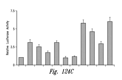
Figures 124 A-C show the results from two gel shift experiments (panels A and
B) and a luciferase activity (reporter gene) assay (panel C) that examined the
effects of
RNS60 on the activation of NFKB in MBP-primed T cells.
DETAILED DESCRIPTION OF THE INVENTION
Certain embodiments disclosed herein relate to providing compositions and
methods of treatment of insulin resistance and/or a diabetic condition or
disorder, or at
least one symptom thereof, by administering to a subject, a therapeutic
composition
comprising a gas-enriched fluid. In certain specific embodiments, the gas-
enriched fluid
comprises oxygen-enriched water.
Diabetic disorders and conditions
Certain embodiments herein relate to therapeutic compositions and methods of
treatment for a subject by preventing or alleviating at least one symptom of
insulin
resistance and/or a diabetic associated condition or disease.
In further embodiments herein relating to the therapeutic compositions and
methods of treatment for preventing or alleviating complications related to
insulin
resistance and/or diabetic-associated condition, including alleviating the
symptoms of
diabetic retinopathy, for example.
14
CA 02758738 2011-10-13
WO 2010/126908 PCT/US2010/032620
Electrokinetically-generated fluids:
"Electrokinetically-generated fluid," as used herein, refers to Applicants'
inventive
electrokinetically-altered fluids generated, for purposes of the working
Examples herein,
by the exemplary Mixing Device described in detail herein (see also
US200802190088
and W02008/052143, both incorporated herein by reference in their entirety).
The
electrokinetic fluids, as demonstrated by the data disclosed and presented
herein,
represent novel and fundamentally distinct fluids relative to prior art non-
electrokinetic
fluids, including relative to prior art oxygenated non-electrokinetic fluids
(e.g., pressure
pot oxygenated fluids and the like). As disclosed in various aspects herein,
the
electrokinetically-generated fluids have unique and novel physical and
biological
properties including, but not limited to the following:
In particular aspects, the electrokinetically altered aqueous fluid comprise
an
ionic aqueous solution of charge-stabilized oxygen-containing nanostructures
substantially having an average diameter of less than about 100 nanometers and
stably
configured in the ionic aqueous fluid in an amount sufficient to provide, upon
contact of
a living cell by the fluid, modulation of at least one of cellular membrane
potential and
cellular membrane conductivity.
In particular aspects, electrokinetically-generated fluids refers to fluids
generated
in the presence of hydrodynamically-induced, localized (e.g., non-uniform with
respect
to the overall fluid volume) electrokinetic effects (e.g., voltage/current
pulses), such as
device feature-localized effects as described herein. In particular aspects,
said
hydrodynamically -induced, localized electrokinetic effects are in combination
with
surface-related double layer and/or streaming current effects as disclosed and
discussed herein.
In particular aspects the administered inventive electrokinetically-altered
fluids
comprise charge-stabilized oxygen-containing nanostructures in an amount
sufficient to
provide modulation of at least one of cellular membrane potential and cellular
membrane conductivity. In certain embodiments, the electrokinetically-altered
fluids are
superoxygenated (e.g., RNS-20, RNS-40 and RNS-60, comprising 20 ppm, 40 ppm
and
60 ppm dissolved oxygen, respectively, in standard saline). In particular
embodiments,
the electrokinetically-altered fluids are not-superoxygenated (e.g., RNS-10 or
Solas,
comprising 10 ppm (e.g., approx. ambient levels of dissolved oxygen in
standard
CA 02758738 2011-10-13
WO 2010/126908 PCT/US2010/032620
saline). In certain aspects, the salinity, sterility, pH, etc., of the
inventive
electrokinetically-altered fluids is established at the time of electrokinetic
production of
the fluid, and the sterile fluids are administered by an appropriate route.
Alternatively, at
least one of the salinity, sterility, pH, etc., of the fluids is appropriately
adjusted (e.g.,
using sterile saline or appropriate diluents) to be physiologically compatible
with the
route of administration prior to administration of the fluid. Preferably, and
diluents
and/or saline solutions and/or buffer compositions used to adjust at least one
of the
salinity, sterility, pH, etc., of the fluids are also electrokinetic fluids,
or are otherwise
compatible.
In particular aspects, the inventive electrokinetically-altered fluids
comprise
saline (e.g., one or more dissolved salt(s); e.g., alkali metal based salts
(Li+, Na+, K+,
Rb+, Cs+, etc.), alkaline earth based salts (e.g., Mg++, Ca++), etc., or
transition metal-
based positive ions (e.g., Cr, Fe, Co, Ni, Cu, Zn, etc.,), in each case along
with any
suitable anion components, including, but not limited to F-, Cl-, Br-, I-, P04-
, S04-, and
nitrogen-based anions. . Particular aspects comprise mixed salt based
electrokinetic
fluids (e.g., Na+, K+, Ca++, Mg++, transition metal ion(s), etc.) in various
combinations
and concentrations, and optionally with mixtures of couterions. In particular
aspects,
the inventive electrokinetically-altered fluids comprise standard saline
(e.g., approx.
0.9% NaCl, or about 0.15 M NaCI). In particular aspects, the inventive
electrokinetically-altered fluids comprise saline at a concentration of at
least 0.0002 M,
at least 0.0003 M, at least 0.001 M, at least 0.005 M, at least 0.01 M, at
least 0.015 M,
at least 0.1 M, at least 0.15 M, or at least 0.2 M. In particular aspects, the
conductivity
of the inventive electrokinetically-altered fluids is at least 10 S/cm, at
least 40 S/cm,
at least 80 pS/cm, at least 100 pS/cm, at least 150 pS/cm, at least 200 pS/cm,
at least
300 pS/cm, or at least 500 pS/cm, at least 1 mS/cm, at least 5, mS/cm, 10
mS/cm, at
least 40 mS/cm, at least 80 mS/cm, at least 100 mS/cm, at least 150 mS/cm, at
least
200 mS/cm, at least 300 mS/cm, or at least 500 mS/cm. In particular aspects,
any salt
may be used in preparing the inventive electrokinetically-altered fluids,
provided that
they allow for formation of biologically active salt-stabilized nanostructures
(e.g., salt-
stabilized oxygen-containing nanostructures) as disclosed herein.
According to particular aspects, the biological effects of the inventive fluid
compositions comprising charge-stabilized gas-containing nanostructures can be
16
CA 02758738 2011-10-13
WO 2010/126908 PCT/US2010/032620
modulated (e.g., increased, decreased, tuned, etc.) by altering the ionic
components of
the fluids, and/or by altering the gas component of the fluid.
According to particular aspects, the biological effects of the inventive fluid
compositions comprising charge-stabilized gas-containing nanostructures can be
modulated (e.g., increased, decreased, tuned, etc.) by altering the gas
component of
the fluid. In preferred aspects, oxygen is used in preparing the inventive
electrokinetic
fluids. In additional aspects mixtures of oxygen along with at least one other
gas
selected from Nitrogen, Oxygen, Argon, Carbon dioxide, Neon, Helium, krypton,
hydrogen and Xenon. As described above, the ions may also be varied, including
along with varying the gas constitutent(s).
Given the teachings and assay systems disclosed herein (e.g., cell-based
cytokine assays, patch-clamp assays, etc.) one of skill in the art will
readily be able to
select appropriate salts and concentrations thereof to achieve the biological
activities
disclosed herein.
TABLE 1. Exemplary cations and anions.
Common Cations:
Name Formula Other name(s)
Aluminum Al +3
Ammonium NH4+
Barium Ba+2
Calcium Ca+2
Chromium(II) Cr+2 Chromous
Chromium(III) Cr+3 Chromic
Copper(l) Cu+ Cuprous
Copper(II) Cu+2 Cupric
Iron(II) Fe +2 Ferrous
Iron(III) Fe +3 Ferric
Hydrogen H+
Hydronium H3O+
Lead(II) Pb+2
Lithium Li+
Magnesium Mg +2
Manganese(II) Mn+2 Manganous
Manganese(III) Mn+3 Manganic
17
CA 02758738 2011-10-13
WO 2010/126908 PCT/US2010/032620
Mercury(I) Hg2+2 Mercurous
Mercury(II) Hg +2 Mercuric
Nitronium NO2+
Potassium K+
Silver Ag+
Sodium Na+
Strontium Sr+2
Tin(11) Sn+2 Stannous
Tin(IV) Sn+4 Stannic
Zinc Zn+2
Common Anions:
Simple ions:
Hydride H- Oxide 02-
Fluoride F- Sulfide S2-
Chloride Cl- Nitride N3-
Bromide Br
Iodide I-
Oxoanions:
Arsenate As043- Phosphate P043_
Arsenite As033- Hydrogen phosphate HP042-
Dihydrogen phosphate H2PO4-
Sulfate S042- Nitrate N03-
Hydrogen sulfate HS04- Nitrite N02-
Thiosulfate S2032-
Sulfite S032-
Perchlorate C104- Iodate 103-
Chlorate C103- Bromate Br03-
Chlorite C102-
Hypochlorite OCI- Hypobromite OBr-
Carbonate C032- Chromate Cr042-
Hydrogen carbonate 2
or Bicarbonate HCO3 Dichromate Cr207
18
CA 02758738 2011-10-13
WO 2010/126908 PCT/US2010/032620
Anions from Organic Acids:
Acetate CH3COO formate HCOO
Others:
Cyanide CN- Amide NH2-
Cyanate OCN- Peroxide 022-
Thiocyanate SCN- Oxalate C2042-
Hydroxide OH- Permanganate Mn04-
TABLE 2. Exemplary cations and anions.
Monoatomic Cations
Formula Charge Name
...............................................................................
...............................................................................
...............................................................................
......
H+ + hydrogen ion
...............................................................................
...............................................................................
...............................................................................
...... .
Li+ 1 + lithium ion
Na 1 + sodium ion
...............................................................................
...............................................................................
...............................................................................
......
KK 1 + potassium ion
...............................................................................
...............................................................................
...............................................................................
...... .
Cs+ 11 + cesium ion
Ag 1 + silver ion
...............................................................................
...............................................................................
...............................................................................
......
Mg2+ 2+ magnesium ion
...............................................................................
...............................................................................
...............................................................................
....... .
Ca2+ I2+ calcium ion
Sr2+ 2+ strontium ion
...............................................................................
...............................................................................
...............................................................................
......
Ba2 2+ :barium ion
...............................................................................
...............................................................................
...............................................................................
....... .
Zn2+ 12+ zinc ion
Cd2+ 2+ cadmium ion
...............................................................................
...............................................................................
...............................................................................
......
AI3+ 3+ aluminum ion
...............................................................................
...............................................................................
...............................................................................
....... .
Polyatomic Cations
........ ......... ......... ......... ....... ......... ......... .........
......... ......... ......... ......... ......... .................
Formula Charge Name
...............................................................................
...............................................................................
...............................................................................
........ .
NH4+ 1 + ammonium ion
H3O+ 1 + hydronium ion
...............................................................................
...............................................................................
...............................................................................
........ .
19
CA 02758738 2011-10-13
WO 2010/126908 PCT/US2010/032620
Multivalent Cations
Formula Charge Name
Cr2+ 2 chromium(II) or chromous ion
...............................................................................
...............................................................................
...............................................................................
....... .
:Cr3+ 3 chromium(III)or chromic ion
...............................................................................
...............................................................................
...............................................................................
......... .
Mn2+ 2 manganese(II) or manganous ion
Mn4+ 4 manganese(IV) ion
...............................................................................
...............................................................................
...............................................................................
....... .
Fe2+ 2 iron(l1) or ferrous ion
...............................................................................
...............................................................................
...............................................................................
......... .
Fe3+ 3 iron(l11) or ferric ion
...............................................................................
...............................................................................
...............................................................................
.........
Co2+ 2 cobalt(11) or cobaltous ion
...............................................................................
...............................................................................
...............................................................................
....... .
Co3+ 3 cobalt(l1) or cobaltic ion
...............................................................................
...............................................................................
...............................................................................
......... .
Ni2+ 2 nickel(11) or nickelous ion
...............................................................................
...............................................................................
...............................................................................
.........
Ni3+ 3 nickel(lll) or nickelic ion
...............................................................................
...............................................................................
...............................................................................
....... .
:Cu+ 1 copper(l) or cuprous ion
Cu2+ 2 copper(l1) or cupric ion
...............................................................................
...............................................................................
...............................................................................
.........
Sn2+ 2 Ãtin(ll) or atannous ion
...............................................................................
...............................................................................
...............................................................................
....... .
:Sn4 4 tin(IV) or atannic ion
Pb2+ 2 lead(l1) or plumbous ion
...............................................................................
...............................................................................
...............................................................................
.........
Pb4+ 4 lead(IV) or plumbic ion
...............................................................................
...............................................................................
...............................................................................
....... .
Monoatomic Anions
Formula Charge Name
...............................................................................
...............................................................................
...............................................................................
......... .
H 1- hydride ion
...............................................................................
...............................................................................
...............................................................................
....... .
F 1- fluoride ion
...............................................................................
...............................................................................
...............................................................................
.......
CI- 1 1- chloride ion
...............................................................................
...............................................................................
...............................................................................
.......
Br 1- bromide ion
...............................................................................
...............................................................................
...............................................................................
........ .
1- iodide ion
...............................................................................
...............................................................................
...............................................................................
........ .
2- oxide ion
...............................................................................
...............................................................................
...............................................................................
......... .
S2 2- sulfide ion
...............................................................................
...............................................................................
...............................................................................
....... .
N3 3- nitride ion
...............................................................................
...............................................................................
...............................................................................
.......
Polyatomic Anions
Formula Charge Name
...............................................................................
...............................................................................
...............................................................................
....... .
CA 02758738 2011-10-13
WO 2010/126908 PCT/US2010/032620
OH Ã1- :hydroxide ion
...............................................................................
...............................................................................
...............................................................................
..... .
CN 1- cyanide ion
...............................................................................
...............................................................................
...............................................................................
......
SCN 1- thiocyanate ion
C2H302 Ã1- acetate ion
...............................................................................
...............................................................................
...............................................................................
..... .
:CIO- hypochlorite ion
...............................................................................
...............................................................................
...............................................................................
......
C102 1- chlorite ion
C103 Ã1- chlorate ion
...............................................................................
...............................................................................
...............................................................................
..... .
C104 1- perchlorate ion
...............................................................................
...............................................................................
...............................................................................
......
N02 1- nitrite ion
N03 Ã1- nitrate ion
...............................................................................
...............................................................................
...............................................................................
...... .
Mn042 2- permanganate ion
...............................................................................
...............................................................................
...............................................................................
......
C032 2- carbonate ion
C2042-
::2- oxalate ion
...............................................................................
...............................................................................
...............................................................................
..... .
Cr042 2- chromate ion
...............................................................................
...............................................................................
...............................................................................
......
Cr2072 2- :dichromate ion
::............................................................::...............
.......................................::......................................
............................................................ .
...............................................................................
...............................................................................
...............................................................................
......... .
S032-
:2- sulfite ion
...............................................................................
...............................................................................
...............................................................................
..... .
SO42 2- sulfate ion
...............................................................................
...............................................................................
...............................................................................
......
P033 ::3- phosphite ion
...............................................................................
...............................................................................
...............................................................................
........ .
P043 3- phosphate ion
...............................................................................
...............................................................................
...............................................................................
....... .
The present disclosure sets forth novel gas-enriched fluids, including, but
not
limited to gas-enriched ionic aqueous solutions, aqueous saline solutions
(e.g.,
standard aqueous saline solutions, and other saline solutions as discussed
herein and
as would be recognized in the art, including any physiological compatible
saline
solutions), cell culture media (e.g., minimal medium, and other culture media)
useful in
the treatment of diabetes or diabetes related disorders. A medium, or media,
is termed
"minimal" if it only contains the nutrients essential for growth. For
prokaryotic host cells,
a minimal media typically includes a source of carbon, nitrogen, phosphorus,
magnesium, and trace amounts of iron and calcium. (Gunsalus and Stanter, The
Bacteria, V. 1, Ch. 1 Acad. Press Inc., N.Y. (1960)). Most minimal media use
glucose
as a carbon source, ammonia as a nitrogen source, and orthophosphate (e.g.,
P04) as
the phosphorus source. The media components can be varied or supplemented
according to the specific prokaryotic or eukaryotic organism(s) grown, in
order to
21
CA 02758738 2011-10-13
WO 2010/126908 PCT/US2010/032620
encourage optimal growth without inhibiting target protein production.
(Thompson et
al., Biotech. and Bioeng. 27: 818-824 (1985)).
In particular aspects, the electrokinetically-altered aqueous fluids are
suitable to
modulate 13C-NMR line-widths of reporter solutes (e.g., Trehelose) dissolved
therein.
NMR line-width effects are an indirect method of measuring, for example,
solute
`tumbling' in a test fluid as described herein in particular working Examples.
In particular aspects, the electrokinetically-altered aqueous fluids are
characterized by at least one of: distinctive square wave voltametry peak
differences at
any one of -0.14V, -0.47V, -1.02V and -1.36V; polarographic peaks at -0.9
volts; and an
absence of polarographic peaks at -0.19 and -0.3 volts, which are unique to
the
electrokinetically-generated fluids as disclosed herein in particular working
Examples.
In particular aspects, the electrokinetically-altered aqueous fluids are
suitable to
alter cellular membrane conductivity (e.g., a voltage-dependent contribution
of the
whole-cell conductance as a measure in patch clamp studies disclosed herein).
In particular aspects, the electrokinetically-altered aqueous fluids are
oxygenated, wherein the oxygen in the fluid is present in an amount of at
least 15, ppm,
at least 25 ppm, at least 30 ppm, at least 40 ppm, at least 50 ppm, or at
least 60 ppm
dissolved oxygen at atmospheric pressure. In particular aspects, the
electrokinetically-
altered aqueous fluids have less than 15 ppm, less that 10 ppm of dissolved
oxygen at
atmospheric pressure, or approximately ambient oxygen levels.
In particular aspects, the electrokinetically-altered aqueous fluids are
oxygenated, wherein the oxygen in the fluid is present in an amount between
approximately 8 ppm and approximately 15 ppm, and in this case is sometimes
referred
to herein as "Solas."
In particular aspects, the electrokinetically-altered aqueous fluid comprises
at
least one of solvated electrons (e.g., stabilized by molecular oxygen), and
electrokinetically-modified and/or charged oxygen species, and wherein in
certain
embodiments the solvated electrons and/or electrokinetically-modified or
charged
oxygen species are present in an amount of at least 0.01 ppm, at least 0.1
ppm, at least
0.5 ppm, at least 1 ppm, at least 3 ppm, at least 5 ppm, at least 7 ppm, at
least 10 ppm,
at least 15 ppm, or at least 20 ppm.
22
CA 02758738 2011-10-13
WO 2010/126908 PCT/US2010/032620
In particular aspects, the electrokinetically-altered aqueous fluids are
suitable to
alter cellular membrane structure or function (e.g., altering of a
conformation, ligand
binding activity, or a catalytic activity of a membrane-associated protein)
sufficient to
provide for modulation of intracellular signal transduction, wherein in
particular aspects,
the membrane-associated protein comprises at least one selected from the group
consisting of receptors, transmembrane receptors (e.g., G-Protein Coupled
Receptor
(GPCR), TSLP receptor, beta 2 adrenergic receptor, bradykinin receptor, etc.),
ion
channel proteins, intracellular attachment proteins, cellular adhesion
proteins, and
integrins. In certain aspects, the effected G-Protein Coupled Receptor (GPCR)
interacts with a G protein a subunit (e.g., Gas , Gai, Gaq, and Gai2).
In particular aspects, the electrokinetically-altered aqueous fluids are
suitable to
modulate intracellular signal transduction, comprising modulation of a calcium
dependant cellular messaging pathway or system (e.g., modulation of
phospholipase C
activity, or modulation of adenylate cyclase (AC) activity).
In particular aspects, the electrokinetically-altered aqueous fluids are
characterized by various biological activities (e.g., regulation of cytokines,
receptors,
enzymes and other proteins, and intracellular signaling pathways) described in
the
working Examples and elsewhere herein.
In particular aspects, the electrokinetically-altered aqueous fluids display
synergy
and/or additive activity with metformin.
In particular aspects, the electrokinetically-altered aqueous fluids reduce
DEP-
induced TSLP receptor expression in bronchial epithelial cells (BEC) as shown
in
working Examples herein.
In particular aspects, the electrokinetically-altered aqueous fluids inhibit
the
DEP-induced cell surface-bound MMP9 levels in bronchial epithelial cells (BEC)
as
shown in working Examples herein.
In particular aspects, the biological effects of the electrokinetically-
altered
aqueous fluids are inhibited by diphtheria toxin, indicating that beta
blockade, GPCR
blockade and Ca channel blockade affects the activity of the
electrokinetically-altered
aqueous fluids (e.g., on regulatory T cell function) as shown in working
Examples
herein.
23
CA 02758738 2011-10-13
WO 2010/126908 PCT/US2010/032620
In particular aspects, the physical and biological effects (e.g., the ability
to alter
cellular membrane structure or function sufficient to provide for modulation
of
intracellular signal transduction) of the electrokinetically-altered aqueous
fluids persists
for at least two, at least three, at least four, at least five, at least six
months, or longer
periods, in a closed container (e.g., closed gas-tight container).
Therefore, further aspects provide said electrokinetically-generated solutions
and
methods of producing an electrokinetically-altered oxygenated aqueous fluid or
solution, comprising: providing a flow of a fluid material between two spaced
surfaces in
relative motion and defining a mixing volume therebetween, wherein the dwell
time of a
single pass of the flowing fluid material within and through the mixing volume
is greater
than 0.06 seconds or greater than 0.1 seconds; and introducing oxygen (02)
into the
flowing fluid material within the mixing volume under conditions suitable to
dissolve at
least 20 ppm, at least 25 ppm, at least 30, at least 40, at least 50, or at
least 60 ppm
oxygen into the material, and electrokinetically alter the fluid or solution.
In certain
aspects, the oxygen is infused into the material in less than 100
milliseconds, less than
200 milliseconds, less than 300 milliseconds, or less than 400 milliseconds.
In
particular embodiments, the ratio of surface area to the volume is at least
12, at least
20, at least 30, at least 40, or at least 50.
Yet further aspects provide a method of producing an electrokinetically-
altered
oxygenated aqueous fluid or solution, comprising: providing a flow of a fluid
material
between two spaced surfaces defining a mixing volume therebetween; and
introducing
oxygen into the flowing material within the mixing volume under conditions
suitable to
infuse at least 20 ppm, at least 25 ppm, at least 30 ppm, at least 40 ppm, at
least
50 ppm, or at least 60 ppm oxygen into the material in less than 100
milliseconds, less
than 200 milliseconds, less than 300 milliseconds, or less than 400
milliseconds. In
certain aspects, the dwell time of the flowing material within the mixing
volume is
greater than 0.06 seconds or greater than 0.1 seconds. In particular
embodiments, the
ratio of surface area to the volume is at least 12, at least 20, at least 30,
at least 40, or
at least 50.
Additional embodiments provide a method of producing an electrokinetically-
altered oxygenated aqueous fluid or solution, comprising use of a mixing
device for
creating an output mixture by mixing a first material and a second material,
the device
24
CA 02758738 2011-10-13
WO 2010/126908 PCT/US2010/032620
comprising: a first chamber configured to receive the first material from a
source of the
first material; a stator; a rotor having an axis of rotation, the rotor being
disposed inside
the stator and configured to rotate about the axis of rotation therein, at
least one of the
rotor and stator having a plurality of through-holes; a mixing chamber defined
between
the rotor and the stator, the mixing chamber being in fluid communication with
the first
chamber and configured to receive the first material therefrom, and the second
material
being provided to the mixing chamber via the plurality of through-holes formed
in the
one of the rotor and stator; a second chamber in fluid communication with the
mixing
chamber and configured to receive the output material therefrom; and a first
internal
pump housed inside the first chamber, the first internal pump being configured
to pump
the first material from the first chamber into the mixing chamber. In certain
aspects, the
first internal pump is configured to impart a circumferential velocity into
the first material
before it enters the mixing chamber.
Further embodiments provide a method of producing an electrokinetically-
altered
oxygenated aqueous fluid or solution, comprising use of a mixing device for
creating an
output mixture by mixing a first material and a second material, the device
comprising:
a stator; a rotor having an axis of rotation, the rotor being disposed inside
the stator and
configured to rotate about the axis of rotation therein; a mixing chamber
defined
between the rotor and the stator, the mixing chamber having an open first end
through
which the first material enters the mixing chamber and an open second end
through
which the output material exits the mixing chamber, the second material
entering the
mixing chamber through at least one of the rotor and the stator; a first
chamber in
communication with at least a majority portion of the open first end of the
mixing
chamber; and a second chamber in communication with the open second end of the
mixing chamber.
Additional aspects provide an electrokinetically-altered oxygenated aqueous
fluid
or solution made according to any of the above methods.
Diabetes and Insulin Resistance
Diabetes mellitus is a serious lifelong metabolic disease that is defined by
the
presence of chronically elevated levels of blood glucose (hyperglycemia). This
state of
hyperglycemia is the result of a relative or absolute lack of activity of the
peptide
CA 02758738 2011-10-13
WO 2010/126908 PCT/US2010/032620
hormone, insulin. Insulin is produced and secreted by the 0 cells of the
pancreas.
Insulin promotes glucose utilization, protein synthesis, and the formation and
storage of
carbohydrate energy as glycogen. Glucose is stored in the body as glycogen, a
form of
polymerized glucose, which may be converted back into glucose to meet
metabolism
requirements. Under normal conditions, insulin is secreted at both a basal
rate and at
enhanced rates following glucose stimulation, all to maintain metabolic
homeostasis by
the conversion of glucose into glycogen.
The term diabetes mellitus encompasses several different hyperglycemic states.
These states include Type 1 (insulin-dependent diabetes mellitus or IDDM) and
Type 2
(non-insulin dependent diabetes mellitus or NIDDM) diabetes. Type 1 diabetes
is
associated with deficient, reduced, or nonexistent levels of insulin that are
insufficient to
maintain blood glucose levels within the physiological range.
Type 2 diabetes is an increasingly prevalent disease of aging. It is initially
characterized by decreased sensitivity to insulin or insulin resistance and a
compensatory elevation in circulating insulin concentrations, the latter of
which is
required to maintain normal blood glucose levels. Increased insulin levels are
caused
by increased secretion from the pancreatic R cells, and the resulting
hyperinsulinemia is
associated with cardiovascular complications of diabetes. As insulin
resistance
worsens, the demand on the pancreatic R cells steadily increases until the
pancreas
can no longer provide adequate levels of insulin, resulting in elevated levels
of glucose
in the blood. Ultimately, overt hyperglycemia and hyperlipidemia occur,
leading to the
devastating long-term complications associated with diabetes, including
cardiovascular
disease, renal failure, and blindness.
One specific complication resulting from impaired cardiovascular circulation
caused by Type II diabetes is diabetic retinopathy, where the eye and, more
specifically, the retina undergoes damage due reduced cardiovascular
functioning. In
the retina the damage from lack of circulation initially manifests itself by
weakening of
the arteries which causes them to leak. This leakage results in small, dot-
like
hemorrhages and swelling. As the disease progresses the circulation problems
cause
parts of the retina to become ischemic or oxygen-deprived, resulting in new,
fragile
blood vessels developing as the circulatory system tries to maintain
appropriate oxygen
levels within the retina. This process, called neovascularization, leads to
frequent leaks
26
CA 02758738 2011-10-13
WO 2010/126908 PCT/US2010/032620
of blood into the retina, because the new vessels are delicate and hemorrhage
easily.
In the later phases of diabetes, abnormal vessel growth continues and scar
tissue
develops. The result from the weak vessels and scar tissue can be quite
serious, often
leading to retinal detachment, glaucoma, and blindness.
The exact mechanism(s) causing type 2 diabetes are unknown, but result in
impaired glucose transport into skeletal muscle and increased hepatic glucose
production, in addition to inadequate insulin response. Dietary modifications
are often
ineffective, therefore the majority of patients ultimately require
pharmaceutical
intervention in an effort to prevent and/or slow the progression of the
complications of
the disease. Many patients can be treated with one or more of the many oral
anti-
diabetic agents available, including insulin, alpha-glucosidase inhibitors,
biguanides,
DPP-4 inhibitors, meglitinides, sulfonylureas, and thiazolidinediones.
Alpha-glucosidase inhibitors (including, acarbose and miglitol) are
saccharides
that competitively inhibit certain enzymes that digest carbohydrates,
specifically alpha-
glucosidase enzymes in the small intestines, where the membrane-bound alpha-
glucosidases hydrolyze oligosaccharides, trisaccharides, and disaccharides
into
glucose and other monosaccharides.
Biguanides (such as metformin, buformin, and phenformin) reduce the level of
serum glucose by inhibiting liver gluconeogenesis and by increasing the
absorption of
glucose already present in the blood stream. DPP-4 inhibitors (including
vildagliptin,
sitagliptin, saxagliptin, linagliptin, and alogliptin) are thought to increase
incretin levels
(GLP-1 and GIP). Incretins inhibit the release of glucagon which limits
glucose levels,
increases insulin secretion, and decreases gastric emptying.
Sulfonylureas (including acetohexamide, chlorpropamide, tolbutamide,
tolazamide, glipizide, gliclazide, glibenclamide (glyburide), gliquidone,
glyclopyramide,
and glimepiride) bind to ATP-dependent K+ (KATP) channel on the cell membrane
of
pancreatic 0 cells, thereby increasing the secretion of (pro)insulin.
Sulfonylureas also
are believed to 1) sensitize f3-cells to glucose, 2) limit glucose production
in the liver, 3)
decrease lipolysis (breakdown and release of fatty acids by adipose tissue)
and 4)
decrease clearance of insulin by the liver.
Meglitinides (including nateglinide, mitiglinide, and repaglinide) mechanism
of
action is similar to that of sulfonylureas. Meglitinindes bind to ATP-
dependent K+ (KATP)
27
CA 02758738 2011-10-13
WO 2010/126908 PCT/US2010/032620
channel on the cell membrane of pancreatic R cells, which in turn increases
the
secretion of (pro)insulin.
Thiazolidinediones (including troglitazone, pioglitazone, and rosiglitazone)
bind
to peroxisome proliferator-activated receptors, a group of receptor molecules
inside the
cell nucleus. The normal ligands for these receptors are free fatty acids
(FFAs) and
eicosanoids. When activated, the receptor migrates to the DNA, activating
transcription
of a number of specific genes. The activation of these different genes results
in 1)
decreasing insulin resistance, 2) modifying adipocyte differentiation, 3)
inhibiting VEGF-
induced angiogenesis, 4) decreasing leptin levels (leading to an increased
appetite), 5)
decreasing certain interleukins (e.g. IL-6) levels, and 6) increasing
adiponectin levels.
Recent scientific discoveries have suggested a link between chronic
inflammation and insulin resistance, which is a precursor to diabetes. Solinas
et al.,
Cell Metabolism 6, 386-397 (2007) (hereby incorporated by reference in its
entirety);
Duncan et al., Diabetes 52, 1799-1805 (2003) (hereby incorporated by reference
in its
entirety); Kathryn E. Wellen and Gokhan S. Hotamisligil, J. Clin. Invest. 115,
1111-1119
(2005) (hereby incorporated by reference in its entirety). More specifically,
inflammation induces insulin resistance by promoting serine-phosphorylation of
insulin
receptor substrate-1 (IRS-1), which impairs insulin signaling. By impairing
insulin
signaling, individual cells become more resistant to serum insulin and instead
signal for
the release of glucose (from glycogen) into the blood stream. This suggests
that
pharmacological targeting of inflammation, in particular, might lower insulin
resistance
thereby preventing diabetes. In addition, using a dual approach, combining
anti-
inflammation therapy with diabetes drug treatment might result in enhanced
relief of
insulin resistance and diabetes symptoms.
Inflammation
Inflammation may occur as a defensive response to invasion of the subject by
foreign material, particularly of microbial origin. Additionally, mechanical
trauma, toxins,
and neoplasia may induce inflammatory responses. The accumulation and
subsequent
activation of leukocytes are central events in the pathogenesis of most forms
of
inflammation. Inflammation deficiencies can compromise the host, leaving it
susceptible to worsening infection or trauma. Excessive inflammation, such as
28
CA 02758738 2011-10-13
WO 2010/126908 PCT/US2010/032620
prolonged inflammatory responses, may lead to inflammatory diseases including
but
not limited to insulin resistance, diabetes, arteriosclerosis, cataracts,
chronic skin
disorders, reperfusion injury, and cancer, to post-infectious syndromes such
as in
infectious meningitis, rheumatic fever, and to rheumatic diseases such as
systemic
lupus erythematosus and rheumatoid arthritis. These diseases affect millions
of people
worldwide every year, and lead to increased mortality and morbidity. The
commonality
of the inflammatory response in these varied disease processes makes its
regulation a
major element in the prevention, or treatment, of human disease.
Overproduction of pro-inflammatory cytokines has been implicated in the
pathogenesis of numerous inflammatory and autoimmune diseases. Secretion of
TNFa
is a primary event in the initiation of the inflammatory cascade (Brennan F.
M., et. al.
Lancet, 1989, 2:244-7; Haworth C, et. al. Eur. J. Immunol. 1991, 21:2575-2579)
and
directly contributes to the initiation and maintenance of these diseases,
particularly
insulin resistance and diabetes. Other cytokines also play a role, including
interleukin
113 (IL-113), IL-6, IL-8, IL-12, nitric oxide (NO), IFN-y, granulocyte colony
stimulating
factor (G-CSF), granulocyte macrophage-colony stimulating factor (GM-CSF), and
IL-
10. Certain of these cytokines (e.g., IL-8) may increase or exacerbate an
inflammatory
response, while others (e.g., IL-10) may decrease or alleviate the
inflammatory
response.
Cells of the immune system, macrophages in particular, secrete many of these
cytokines in response to activating stimuli. Target cells of the cytokines may
be
localized in any body compartment and may act via long-distance mechanisms, or
may
act on neighboring cells. Thus, cytokines may regulate inflammation in a
localized or
systemic manner.
Thymic stromal lymphopoietin (TSLP). Thymic stromal lymphopoietin (TSLP) is
an IL-7-like cytokine that triggers dendritic cell-mediated Th2-type
inflammatory
responses and is considered as a master switch for allergic inflammation. TSLP
is an
integral growth factor to both B and T cell development and maturation.
Particularly,
murine TSLP supports B lymphopoieses and is required for B cell proliferation.
Murine
TSLP plays a crucial role in controlling the rearrangement of the T cell
receptor-gamma
(TCR.gamma.) locus and has a substantial stimulatory effect on thymocytes and
mature T cells. See, for example, Friend et al., Exp. Hematol., 22:321-328,
1994; Ray
29
CA 02758738 2011-10-13
WO 2010/126908 PCT/US2010/032620
et al., Eur. J. Immunol., 26:10-16, 1996; Candeias et al., Immunology Letters,
57:9-14,
1997.
TSLP possesses cytokine activity similar to IL-7. For instance, TSLP can
replace IL-7 in stimulating B cell proliferation responses (Friend et al.,
supra). Although
TSLP and IL-7 mediate similar effects on target cells, they appear to have
distinct
signaling pathways and likely vary in their biologic response. For Example,
although
TSLP modulates the activity of STATS, it fails to activate any Janus family
tyrosine
kinase members (Levin et. al., J. Immunol., 162:677-683, 1999).
TSLP effects on dendritic cells and TNF production. After human TSLP and the
human TSLP receptor were cloned in 2001, it was discovered that human TSLP
potently activated immature CD11 c+ myeloid dendritic cells (mDCs) (see, e.g.,
Reche
et al., J. Immunol., 167:336-343, 2001 and Soumelis et al., Nat. Immunol.,
3:673-680,
2002). Th2 cells are generally defined in immunology textbooks and literature
as CD4+
T cells that produce IL-4, IL-5, IL-13, and IL-10, and Th1 cells such as CD4+
T cells
produce IFN-y and sometimes TNF. When TSLP-DCs are used to stimulate naive
allogeneic CD4+ T cells in vitro, a unique type of Th2 cell is induced which
produces
the classical Th2 cytokines IL-4, IL-5, and IL-13, and large amounts of TNF,
but little or
no IL-10 or interferon -y (Reche et al., supra) (see also, e.g., Soumelis et
al., Nat.
Immunol., 3:673-680, 2002). TNF is not typically considered a Th2 cytokine.
However,
TNF is prominent in asthmatic airways and genotypes that correlate with
increased TNF
secretion are associated with an increased asthma risk. See Shah et al., Clin.
Exp.
Allergy., 25:1038-1044, 1995 and Moffatt, M.F. and Cookson, W.O., Hum. Mol.
Genet.,
6:551-554, 1997.
TSLP induces human mDCs to express the TNF superfamily protein OX40L at
both the mRNA and protein level (Ito et al., J. Exp. Med., 202:1213-1223). The
expression of OX40L by TSLP-DCs is important for the elaboration of
inflammatory Th2
cells. Thus, TSLP-activated DCs create a Th2-permissive microenvironment by up-
regulating OX40L without inducing the production of Th1-polarizing cytokines.
Id.
TSLP expression, allergen-specific responses, and asthma. In Early studies
have shown that TSLP mRNA was highly expressed by human primary skin
keratinocytes, bronchial epithelial cells, smooth muscle cells, and lung
fibroblasts
(Soumelis et al., Nat. Immunol., 3:673-680, 2002). Because TSLP is expressed
mainly
CA 02758738 2011-10-13
WO 2010/126908 PCT/US2010/032620
in keratinocytes of the apical layers of the epidermis, this suggests that
TSLP
production is a feature of fully differentiated keratinocytes. TSLP expression
in patients
with atopic dermatitis was associated with Langerhans cell migration and
activation in
situ which suggests that TSLP may contribute directly to the activation of
these cells
which could subsequently migrate into the draining lymph nodes and prime
allergen-
specific responses. Id. In a more recent study, it was shown by in situ
hybridization
that TSLP expression was increased in asthmatic airways and correlated with
both the
expression of Th2-attracting chemokines and with disease severity which
provided a
link between TSLP and asthma (Ying et al., J. Immunol., 174:8183-8190, 2005).
TSLP receptor (TSLPR) and allergy, asthma. The TSLP receptor (TSLPR) is
approximately 50 kDa protein and has significant similarity to the common y-
chain.
TSLPR is a novel type 1 cytokine receptor, which, combined with IL-7Ra
(CD127),
constitutes a TSLP receptor complex as described, for example, in Pandey et
al., Nat.
Immunol., 1:59-64, 2000. TSLPR has a tyrosine residue near its carboxyl
terminus,
which can associate with phosphorylated STATS and mediate multiple biological
functions when engaged with TSLP (Isaksen et al., J. Immunol., 168:3288-3294,
2002).
Human TSLPR is expressed by monocytes and CD11 c+ dendritic cells, and
TSLP binding induces the expression of the TH2 cell-attracting chemokines CCL1
7 and
CCL22. Furthermore, as stated above, the TSLPR-induced activation of dendritic
cells
indirectly results in the increased secretion of TH2 cytokines IL-4, -5 and -
13, which may
be necessary for the regulation of CD4+ T cell homeostasis. In mice,
deficiency of
TSLPR has no effect on lymphocyte numbers. However, a deficiency of TSLPR and
common y-chain results in fewer lymphocytes as compared to mice deficient in
the
common y-chain alone. See Reche et al., J. Immunol., 167:336-343, 2001 and
Soumelis et al., Nat. Immunol., 3:673-680, 2002.
Studies have found that TSLP and the TSLPR play a critical role in the
initiation
of allergic diseases in mice. In one study, it was demonstrated that mice
engineered to
overexpress TSLP in the skin developed atopic dermatitis which is
characterized by
eczematous skin lesions containing inflammatory infiltrates, a dramatic
increase in
circulating Th2 cells and elevated serum IgE (Yoo et al., J. Exp. Med.,
202:541-549,
2005). The study suggested that TSLP may directly activate DCs in mice. In
another
study, conducted by Li et al., the group confirmed that transgenic mice
overexpressing
31
CA 02758738 2011-10-13
WO 2010/126908 PCT/US2010/032620
TSLP in the skin developed atopic dermatitis which solidifies the link between
TSLP
and the development of atopic dermatitis.
Another set of studies demonstrated that TSLP is required for the initiation
of
allergic airway inflammation in mice in vivo. In one study, Zhou et al.
demonstrated that
lunch specific expression of a TSLP transgene induced allergic airway
inflammation
(asthma) which is characterized by massive infiltration of leukocytes
(including Th2
cells), goblet cell hyperplasia, and subepithelial fibrosis, and increased
serum IgE levels
(Zhou et al., Nat. Immunol., 6:1047-1053, 2005). However, in contrast, mice
lacking the
TSLPR failed to develop asthma in response to inhaled antigens (Zhou et al.,
supra and
Al-Shami et al., J. Exp. Med., 202:829-839, 2005). Thus, these studies
together
demonstrate that TSLP is required for the initiation of allergic airway
inflammation in
mice.
Further, in a study conducted by Yong-Jun et al., it was demonstrated that
epithelial cell-derived TSLP triggers DC-mediated inflammatory Th2 responses
in
humans which suggest that TSLP represents a master switch of allergic
inflammation at
the epithelial cell-DC interface (Yong-Jun et al., J. Exp. Med., 203:269-273,
2006).
In a recent study, it was shown that modulation of DCs function by inhibiting
the
TSLPR lessened the severity in mice (Liyun Shi et al., Clin. Immunol., 129:202-
210,
2008). In another set of studies, it was demonstrated that the TSLPR was not
only
expressed in DCs, but also on macrophages, mast cells, and CD4+ T cells
(Rochman
et al., J. Immunol., 178:6720-6724, 2007 and Omori M. and Ziegler S., J.
Immunol.,
178:1396-1404, 2007). In order to rule out the direct effects of the TSLPR
neutralization on CD4+ T cells or other effector cells in allergic
inflammation, Liyun Shi
et al. performed experiments wherein OVA-loaded DCs were in vitro treated with
anti-
TSLPR before adoptive transfer to the airways of naive mice. It has previously
been
found that OVA-DCs triggered strong eosinophilic airway inflammation and
accompanied with massive production of Th2 cytokines such as IL-4 and IL-5
(Sung et
al., J. Immunol., 166:1261-1271 and Lambrecht et al., J. Clin. Invest.,
106:551-559,
2000). However, pretreating OVA-DCs with anti-TSLPR resulted in a significant
reduction of eosinophils and lymphocyte infiltration as well as IL-4 and IL-5
levels,
further illuminating the role that TSLPR plays in DC-primed allergic disease.
This result
32
CA 02758738 2011-10-13
WO 2010/126908 PCT/US2010/032620
also supports that blocking of TSLPR on DCs will aid in controlling airway
inflammation
(Liyun Shi et al., supra).
There has been a growing body of experiments implicating the role of
TSLP/TSLPR in various physiological and pathological processes. Physiological
roles
of TSLP include modulating the immune system, particularly in stimulating B
and T cell
proliferation, development, and maturation. TSLP plays a vital role in the
pathobiology
of allergic asthma and local antibody mediated blockade of TSLP receptor
function to
alleviate allergic diseases. Thus, interplay between TSLP and TSLP receptor is
believed to be important in many physiological disease processes such as:
allergic
inflammation, skin lesions of patients with atopic dermatitis or atopic
eczema, insulin
resistance or diabetes, and asthma.
Inflammation-Associated Conditions or Diseases
Certain embodiments herein relate to therapeutic compositions and methods of
treatment for a subject by preventing or alleviating at least one symptom of
inflammation associated with certain conditions or diseases. For example, the
therapeutic compositions and/or methods disclosed herein may be useful for
treating or
preventing insulin resistance and diabetes.
Methods of Treatment
The term "treating" refers to, and includes, reversing, alleviating,
inhibiting the
progress of, or preventing a disease, disorder or condition, or one or more
symptoms
thereof; and "treatment" and "therapeutically" refer to the act of treating,
as defined
herein.
A "therapeutically effective amount" is any amount of any of the compounds
utilized in the course of practicing the invention provided herein that is
sufficient to
reverse, alleviate, inhibit the progress of, or prevent a disease, disorder or
condition, or
one or more symptoms thereof.
Certain embodiments herein relate to therapeutic compositions and methods of
treatment of a diabetes-associated condition or disorder, or symptoms thereof.
For
33
CA 02758738 2011-10-13
WO 2010/126908 PCT/US2010/032620
example, the therapeutic compositions and/or methods disclosed herein may be
useful
for treating or preventing one or more condition or disease selected from the
group
consisting of: diabetes; insulin-dependent diabetes mellitus or IDDM (Type 1);
non-
insulin dependent diabetes mellitus or NIDDM (Type 2); insulin resistance; and
diabetic
retinopathy.
Many conditions or diseases associated with inflammation have been treated
with steroids, methotrexate, immunosuppressive drugs including
cyclophosphamide,
cyclosporine, azathioprine and leflunomide, nonsteroidal anti-inflammatory
agents such
as aspirin, acetaminophen and COX-2 inhibitors, gold agents and anti-malarial
treatments. These drugs have a variety of disadvantages, and adverse reactions
including injection site reactions, rash, upper respiratory infections,
autoimmune
disorders and increased susceptibility to infections. In addition, many anti-
inflammatory
pharmaceutical drugs require intravenous (IV) or subcutaneous (SC)
administration, as
opposed to more convenient and compliant oral or topical dermal routes.
Accordingly,
a need still exists for the development of novel medicaments and treatment
methods for
conditions and diseases relating to inflammation.
Combination therapy
Additional aspects provide the herein disclosed inventive methods, further
comprising combination therapy, wherein at least one additional therapeutic
agent is
administered to the patient. In certain aspects, the at least one additional
therapeutic
agent is selected from the group consisting of insulin, alpha-glucosidase
inhibitors,
biguanides, DPP-4 inhibitors, meglitinides, sulfonylureas, and
thiazolidinediones.
In particular embodiments, the at least one additional therapeutic agent is
selected from the group consisting of: alpha-glucosidase inhibitors consisting
of
acarbose and miglitol; biguanides consisting of metformin, buformin, and
phenformin;
DPP-4 inhibitors, consisting of vildagliptin, sitagliptin, saxagliptin,
linagliptin, and
alogliptin; sulfonylureas, consisting of acetohexamide, chlorpropamide,
tolbutamide,
tolazamide, glipizide, gliclazide, glibenclamide (glyburide), gliquidone,
glyclopyramide,
and glimepiride; meglitinides consisting of nateglinide, mitiglinide, and
repaglinide;
34
CA 02758738 2011-10-13
WO 2010/126908 PCT/US2010/032620
thiazolidinediones, consisting of troglitazone, pioglitazone, and
rosiglitazone; and
combinations thereof.
Additional aspects provide the herein-disclosed inventive methods, further
comprising combination therapy with a TSLP and/or TSLPR antagonist (e.g.,
neutralizing antibodies specific for TSLP and the TSLP receptor, soluble TSLP
receptor
molecules, and TSLP receptor fusion proteins, such as TSLPR-immunoglobulin Fc
molecules or polypeptides that encode components of more than one receptor
chain,
that thereby mimic a physiological receptor heterodimer or higher order
oligomer. If the
receptor includes more than one polypeptide chain, a single chain fusion can
be
utilized).
Therapeutic treatments for inflammation and/or diabetes include a wide array
of
pharmaceutical drugs administered intravenously, subcutaneously, topically, or
orally
depending on the outcome sought. However, most of the anti-inflammatory
treatments
available today have considerable drawbacks, including severe reactions at
injection
site, increased susceptibility to infection, rash, or other side effects.
Thus, there is a
need for better anti-inflammatory therapeutics and treatment methods.
Anti-inflammatory Activity of the Electrokinetically-generated Gas-Enriched
Fluids and
Solutions:
According to certain aspects of the present invention, the gas-enriched fluids
and/or solutions disclosed herein have anti-inflammatory properties and
effects, and
can be used as anti-inflammatory agents for the treatment of subjects
afflicted by
diseases or disorders relating to inflammation. Figure 38 shows the
experimental
results of cytokine profiles in stimulated lymphocytes from a healthy blood
donor. As
can be seen in Figure 38, the inventive oxygen-enriched fluid (water) affected
a down
regulation of particular cytokines, especially IL-6, IL-8, and IL-1 B.
Increased production of pro-inflammatory cytokines has been implicated in the
pathogenesis of numerous inflammatory and autoimmune diseases. Secretion of
TNFa
is a primary event in the initiation of the inflammatory cascade (Brennan F.
M., et. al.
Lancet, 1989, 2:244-7; Haworth C, et. al. Eur. J. Immunol. 1991, 21:2575-2579)
and
directly contributes to the initiation and maintenance of inflammatory and
autoimmune
diseases. Other pro-inflammatory cytokines also play a role, including
interleukin 1 f3
CA 02758738 2011-10-13
WO 2010/126908 PCT/US2010/032620
(IL-113), IL-6, IL-8, IL-12 nitric oxide, IFN-y and GM-CSF, while anti-
inflammatory
cytokines such as IL-10 may reduce disease. Cells of the immune system,
macrophages in particular, secrete many of these cytokines in response to
activating
stimuli.
A variety of cell types are involved in the inflammatory process.
Overproduction
of TNFa by monocytes, macrophages, and other immune cells is a key element in
the
pathogenesis of a multitude of diseases. Macrophages and T cells in particular
play a
central role in the initiation and maintenance of the immune response. Once
activated
by pathological or immunogenic stimuli, macrophages respond by releasing a
host of
cytokines, including TNF-a, IL-1 B, IL-8, IL-12, nitric oxide (NO), IL-6, GM-
CSF, G-CSF,
M-CSF and others. T cells release IL-2, IL-4, INF-y, and other inflammatory
cytokines.
These cytokines activate other immune cells and some can also act as
independent
cytotoxic agents. Excessive release of macrophage and T cell-derived
inflammatory
mediators can particularly lead to damage of normal cells and surrounding
tissues.
Pro-inflammatory cytokines have been implicated to contribute to many diseases
and disease symptoms including diabetes. The induction of NO from smooth
muscle
cells mediates decreased mean arterial pressure and systemic vascular
resistance
during septic shock, suggesting a fundamental role for NO. Thus, therapies
that target
downregulatory effects on IL-8, IL-1 B, and NO could be beneficial in the
treatment of
inflammatory diseases or disorders, including sepsis, septic shock, endotoxic
shock,
and diabetes.
Overproduction of TNFa contributes to the clinical features of numerous
autoimmune diseases such as diabetes and rheumatoid arthritis. Systemic lupus
erythematosus (SLE) is also precipitated by increased IL-1 B and TNFa levels.
Within
lupus patients, serum C-reactive protein, IL-1 B, and TNFa levels were higher
than in
controls, suggesting that an increased inflammatory response plays a role in
the
disease (Liou L. B. Clin. Exp. Rheumatol. 2001, 19:515-523). A study of
patients with
one form of SLE, neuropsychiatric lupus erythematosus (NPLE), showed that the
number of peripheral blood mononuclear cells expressing mRNA for TNFa as well
as
the cerebrospinal fluid level of NO metabolites correlated with NPLE disease
severity
(Svenungsson E., et al. Ann. Rheum. Dis. 2001, 60:372-9).
36
CA 02758738 2011-10-13
WO 2010/126908 PCT/US2010/032620
IL-1 and TNFa play a central role in various acute as well as chronic
responses
in animal models. Additionally, IL-11, IFNa, and IFN13 may also up-regulate
inflammatory reactions. Conversely, several cytokines may be involved in down-
regulation of inflammatory responses (i.e. IL-4, IL-10, IL-13, among others).
As set
forth in Example 1, cells contacted with the inventive gas-enriched fluid
showed an
increase in IFN-y levels with T3 antigen than in the control culture media
with T3
antigen, while IL-8 was lower in the inventive gas-enriched culture media with
T3
antigen than in the control culture media with T3 antigen. Additionally, IL-6,
IL-8, and
TNF-a levels were lower in the inventive gas-enriched media with PHA, than in
the
control media with PHA, while IL-1 f3 levels were lower in the inventive gas-
enriched
fluid with PHA when compared with control media with PHA. In the inventive gas-
enriched media alone, IFN-y levels were higher than in control media. These
results
are consistent with an anti-inflammatory microenvironment.
NO is recognized as a mediator and regulator of inflammatory responses. It
possesses cytotoxic properties toward pathogens, but can also have deleterious
effects
on the subject's own tissues. (Korhonen et al., Curr Drug Targets Inflamm
Allergy 4(4):
471-9, 2005). NO reacts with soluble guanylate cyclase to form cyclic
guanosine
monophosphate (cGMP), which mediates many of the effects of NO. NO can also
interact with molecular oxygen and superoxide anion to produce reactive oxygen
species that can modify various cellular functions. These indirect effects of
NO have a
significant role in inflammation, where NO is produced in high amounts by
inducible NO
synthase (iNOS) and reactive oxygen species are synthesized by activated
inflammatory cells. In fact, overproduction of NO contributes to impairment of
both
muscle cell insulin action and f3 cell function in obesity, which can lead to
insulin
resistance and diabetes.
NO can be produced by keratinocytes, fibroblasts, endothelial cells, and
possibly
others. Some of the vascular actions of NO include vasodilation, inhibiting
platelet
adhesion to the vascular endothelium, inhibiting leukocyte adhesion to the
vascular
endothelium, and scavenging superoxides. (Shah et al., Env. Health Persp. v.
106 (5):
1139-1143.)
Furthermore, inhibition of NO synthesis has been shown to delay wound
contraction, alter collagen organization, and alter neoepidermis thickness.
(Amadeu
37
CA 02758738 2011-10-13
WO 2010/126908 PCT/US2010/032620
and Costa, J. Cutan. Pathol. 33: 465-473, 2006.) Mast cell migration and
angiogenesis
in wounds is also affected by inhibition of NO. (Id.) Without being bound to
any
particular theory of mechanism, in certain embodiments the inventive gas-
enriched
fluids may be modulating localized and/or cellular NO production, or
degradation,
consistent with the spectrum of wound healing effects illustrated in the
Examples
section disclosed herein. Due to variable pathways of regulation, in certain
embodiments, the inventive gas-enriched fluid may increase NO production
and/or
retard NO degradation, whereas in other certain embodiments, the inventive gas-
enriched fluid may decrease NO production and/or hasten NO degradation.
Specifically, wounds treated with oxygen-enriched saline solution showed an
increase in wound healing at days 4 through 11, and between days 3 and 11, the
new
epidermis in wounds treated with the oxygen-enriched saline solution migrated
at two to
four times as fast as the epidermis of the wounds treated with the normal
saline
solution, as set forth in Example 8 herein. The study also showed that between
15 and
22 days, wounds treated by the oxygen-enriched saline solution differentiated
at a more
rapid rate as evidenced by the earlier formation of more mature epidermal
layers. At all
stages, the thickening that occurs in the epidermis associated with normal
healing did
not occur within the wounds treated by the oxygen-enriched saline solution.
Thus, in accordance with this spectrum of wound-healing effects, but without
wishing to be bound by any particular theory, it is believed that the oxygen-
enriched
saline solution may modulate the localized and/or cellular level of NO within
the
wounds. NO modulates growth factors, collagen deposition, inflammation, mast
cell
migration, epidermal thickening, and neovascularization in wound healing.
Furthermore, nitric oxide is produced by an inducible enzyme that is regulated
by
oxygen.
In the case of mast cell migration, differences also occurred in early and
late
migration for the oxygen-enriched solution. This is consistent with what is
known in the
art regarding inhibition of NO synthesis (Amadeu and Costa, J. Cutan Pathol
33: 465-
473, 2006).
Referring now to Figure 41 A through 41 F, various illustrations compare the
wound healing results of the porcine epidermal tissues with or without oxygen-
enriched
38
CA 02758738 2011-10-13
WO 2010/126908 PCT/US2010/032620
saline solution. As can be seen, the healing of the control wound and of the
wound
using the oxygen-enriched saline solution was followed for days 1, 4, and 16.
Figure 41 A illustrates the wound healing for the control wound on day 1. As
can
be seen, the wound shows epidermal/dermal thickening and a loss of contour.
Figure
41 B illustrates the wound healing on day 1 for the wound treated using the
oxygen-
enriched saline solution. The wound shows normal epidermal/dermal thickness
and
normal contouring is typical on a new wound.
Referring now to Figures 41 C and 41 D, there are illustrated the wound
healing
for the control wound on day 4 and the wound healing for the wound treated
with the
oxygen-enriched saline solution on day 4. For the control wound illustrated in
Figure
41 C, the wound shows a 600 micron epidermal spur. In the wound treated with
the
oxygen-enriched saline solution in Figure 41 D, there is illustrated a 1200
micron
epidermal spur. Thus, in the first 4 days of the experiment, the epidermal
spur created
in the wound treated using the oxygen-enriched saline solution shows an
epidermal
growth rate of twice of that of the wound that was not treated with the oxygen-
enriched
saline solution.
Referring now to Figure 41 E, there is illustrated the control wound at day
16.
The wound shows less differentiated epidermis with loss of epidermal/dermal
contour
than that illustrated by the wound treated with the oxygen-enriched saline
solution,
illustrated in Figure 41 F. Figure 41 F shows more differentiated epidermis
and more
normal epidermal/dermal contouring in the wound.
In the first two phases of the inflammatory process, the foreign body is
either
destroyed, for example, if the foreign body is an organism, or the tissue
around it is
loosened, for example, if it is a splinter. In the healing phase, the
inflammation begins to
subside, individual blood vessels and vascular patterns become normal once
again,
and repair of the wound commences. The three main events in the repair process
are:
(1) formation of new connective tissue by proliferating fibroblasts, (2)
regeneration of
epithelium, and (3) outgrowth of new capillaries.
Even before the inflammation subsides, fibroblasts begin moving into the
injured
area from the surrounding normal tissue, where they usually exist in a dormant
state.
They migrate by an amoeboid movement along strands of fibrin and distribute
themselves throughout the healing area. Once fixed into position in the
injured tissue,
39
CA 02758738 2011-10-13
WO 2010/126908 PCT/US2010/032620
they begin to synthesize collagen and secrete this protein, which arranges
itself into
fibers. The fibers orient themselves with their longitudinal axes in the
direction of the
greatest stress. As the collagen bundles grow in firmness, the fibroblasts
gradually
degenerate and attach closely to the bundles, and the injured area transforms
into scar
tissue.
Simultaneously with scar tissue formation, the intact epidermal cells on the
edge
of the wound begin to proliferate and move, as one sheet, toward the center of
the
injured area. As the inflammation subsides, a need for a direct supply of
blood arises,
and angiogenesis occurs at the wound site.
Inflammation is a complex process that involves multiple cell types. For
example, mast cells release mediators that trigger an early phase of
vasodilation,
accompanied by the separation of endothelial cells and exposure of collagen
fibers in
the subendothelial layer. Fibers in the intercellular gaps that form in blood
vessels trap
platelets and trigger the release of mediators from these cells.
In addition to platelets, the exposed collagen fibers also interact with
proteins of
the plasma that filter through the pores of the dilated vessel wall, including
the
triggering factor of the blood-clotting cascade, increased vasodilation,
increased blood
vessel permeability, and chemotaxis.
Additionally, the complement cascade can be activated by several stimuli: the
injured blood vessels, the proteolytic enzymes released by the damaged cells,
the
membrane components of any participating bacteria, and antigen-antibody
complexes.
Some of the activated complement components act as chemotactic factors,
responsible
for the influx of leukocytes into the inflamed area, while others facilitate
phagocytosis
and participate in cell lysis.
In addition, it is believed that the inventive gas-enriched fluids or
solutions may
also regulate at least one cytokine involved in at least one aspect of
inflammation, the
cytokine(s) including, but not limited to MAF (macrophage activating factor),
MMIF
(macrophage migration inhibition factor), MCF (macrophage chemotactic factor),
LMIF
(leukocyte migration inhibition factor), HRFs (histamine releasing factors),
TF (transfer
factors), interleukins (IL-1, IL-2, IL-3, IL-4, IL-5, IL-6, IL-7, IL-8, IL-9,
IL-10, IL-11, IL-12,
IL-13, IL-14, IL-15, etc.), TNF-a, TNF-f3, interferons (IFN-a, IFN-f3, IFN-y,
IFN-4, IFN-d,
etc.), G-CSF (granulocyte colony stimulating factor), GM-CSF (granulocyte-
CA 02758738 2011-10-13
WO 2010/126908 PCT/US2010/032620
macrophage CSF), M-CSF (macrophage CSF), multi-CSF (IL-3), fibroblast growth
factor (aFGF, bFGF), EGF (epidermal growth factor), NGF (nerve growth factor),
PDGF
(platelet-derived growth factor), VEGF (vascular endothelial growth factor),
transforming
growth factors (TGF-a, TGF-13, etc.), NAP-2 (neutrophil-activating protein 2),
PF-4
(platelet factor 4), thromboglobulin, MCP-1 (monocyte chemoattractant protein
1),
MCP-3, MIP-1a, MIP-113-+ (macrophage inflammatory proteins), RANTES (regulated
upon activation normal T expressed and presumably secreted chemokine), HSPs
(heat
shock proteins), GRPs (glucose-regulated proteins), ubiquitin, and others.
Thus, in certain embodiments, the gas-enriched fluids and/or therapeutic
compositions may increase production and/or secretion of anti-inflammatory
molecules
or cytokines or decrease the degradation of anti-inflammatory molecules or
cytokines,
thereby alleviating or preventing at least one symptom of inflammation. In
other
embodiments, the gas-enriched fluids and/or therapeutic compositions of the
present
invention may decrease production and/or secretion of pro-inflammatory
molecules or
cytokines or increase the degradation of pro-inflammatory molecules or
cytokines,
thereby alleviating or preventing at least one symptom of inflammation.
Previous studies had shown a critical role of anti-MOG antibodies in
augmentation of demyelination and worsening of EAE (experimental autoimmune
encephalomyelitis), an animal model system for the human autoimmune disorder
of
rheumatoid arthritis. (Linington, et al. 1992. J. Neuroimmunol. 40:219-224).
Additionally, antibodies against MOG have been implicated in the pathogenesis
of
multiple sclerosis. (Berger et al. N. Engl. J. Med. 2003 Jul 10;349(2):139-
45).
As set forth in Figure 48 and Example 12, the inventive gas-enriched fluid of
the
present invention amplifies the lymphocyte response to an antigen for which an
animal
was previously primed. As indicated in Figure 48, lymphocyte proliferation was
greater
for response to MOG challenge when cultured in fluid reconstituted with the
inventive
gas-enriched fluid comprising solvated electrons, when compared with
pressurized,
oxygenated fluid (pressure pot) or control deionized fluid.
Inventive Gas-Enriched Fluids and Solutions
Diffusing or enriching a fluid with another fluid may result in a solution or
suspension of the two fluids. In particular, enriching a liquid with a gas
(e.g. oxygen)
41
CA 02758738 2011-10-13
WO 2010/126908 PCT/US2010/032620
may be beneficial for certain applications, including therapeutic treatments.
As utilized
herein, "fluid," may generally refer to a liquid, a gas, a vapor, a mixture of
liquids and/or
gases, or any combination thereof, for any particular disclosed embodiment.
Furthermore, in certain embodiments a "liquid" may generally refer to a pure
liquid or
may refer to a gel, sol, emulsion, fluid, colloid, dispersion, or mixture, as
well as any
combination thereof, any of which may vary in viscosity.
In particular embodiments disclosed herein, the dissolved gas comprises
ambient air. In a preferred embodiment, the dissolved gas comprises oxygen. In
another embodiment, the dissolved gas comprises nitric oxide.
There are several art-recognized methods of gas-enriching liquids (such as
oxygen-enriching water). For example, a turbine aeration system can release
air near a
set of rotating blades of an impeller, which mixes the air or oxygen with the
water, or
water can be sprayed into the air to increase its oxygen content.
Additionally, other
systems on the market inject air or oxygen into the water and subject the
water/gas to a
large-scale vortex. Naturally occurring levels of oxygen in water are
typically no more
than 10 ppm (parts per million), which is considered to be a level of 100%
dissolved
oxygen. Tests on certain devices have shown that under ideal conditions, the
device
can attain upwards of approximately 20 ppm, or twice the natural oxygen levels
of
water. In certain embodiments, the oxygen level may be even higher.
In certain embodiments disclosed herein, a gas-enriched fluid of the present
invention provides an anti-inflammatory benefit. Certain embodiments disclosed
herein
relate to a therapeutic composition comprising a gas-enriched fluid of the
present
invention, and optionally at least one additional therapeutic agent, such as a
pharmaceutical drug, a metal, a peptide, a polypeptide, a protein, a
nucleotide, a
carbohydrate or glycosylated protein, a fat (including oils or waxes), or
other agent that
prevents or alleviates at least one symptom of a condition or disease
associated with
inflammation.
Furthermore, certain embodiments disclosed herein include therapeutic
compositions and methods related to inflammation of wounds. Wound care is
desirable
to improve health and appearance of underlying dermal tissues. Wounds, either
injury
induced, such as cuts, abrasions or blisters, or surgically induced, such as
surgical
incisions or ostomiess, require localized treatment to remedy the affected
area and to
42
CA 02758738 2011-10-13
WO 2010/126908 PCT/US2010/032620
prevent further dermal damage. If wounds are not properly treated, further
dermal
irritation can result, such as inflammation, and may result in secondary
infections and
further discomfort to the subject.
Particular embodiments provided herein relate to a diffuser-processed
therapeutic fluid as defined herein, comprising: a fluid host material; an
infusion
material diffused into the host material; and optionally, at least one
therapeutic agent
dispersed in the host material, wherein the infusion material comprises oxygen
micro-
bubbles in the host fluid, wherein the majority of the micro-bubbles are less
than 0.2
microns, or preferably less than 0.1 microns in size. In certain embodiments,
the
dissolved oxygen level in the infused fluid host material may be maintained at
greater
than about 30 ppm at atmospheric pressure for at least 13 hours. In other
particular
embodiments, the dissolved oxygen level in the infused fluid host material may
be
maintained at greater than 40 ppm at atmospheric pressure for at least 3
hours.
In additional embodiments, the infused fluid host material further comprises a
saline solution. In further embodiments, the infused fluid host material
maintains a
dissolved oxygen level of at least about 20 ppm to about 40 ppm for a period
of at least
100 days, preferably at least 365 days within a sealed container at
atmospheric
pressure. In certain embodiments, the infused fluid host material may have a
dissolved
oxygen level of at least 50 ppm at atmospheric pressure.
In certain embodiments, the infused fluid host material exhibits Rayleigh
scattering for a laser beam shining therethrough for a selected period of time
after the
oxygen has been diffused into therein.
Table 3 illustrates various partial pressure measurements taken in a healing
wound treated with an oxygen-enriched saline solution and in samples of the
gas-
enriched oxygen-enriched saline solution of the present invention.
TABLE 3
TISSUE OXYGEN MEASUREMENTS
Probe Z082BO
In air: 171 mmHg 230 C
Column Partial Pressure (mmHg)
131 32-36
B2 169-200
43
CA 02758738 2011-10-13
WO 2010/126908 PCT/US2010/032620
B3 20-180*
B4 40-60
*wound depth minimal, majority >150, occasional 20 s
BUBBLE SIZE MEASUREMENTS
Experimentation was performed to determine a size of the bubbles of gas
diffused within the fluid by the mixing device 100. While experiments were not
performed to measure directly the size of the bubbles, experiments were
performed that
established that the bubble size of the majority of the gas bubbles within the
fluid was
smaller than 0.1 microns. In other words, the experiments determined a size
threshold
value below which the sizes of the majority of bubbles fall.
This size threshold value or size limit was established by passing the output
material 102 formed by processing a fluid and a gas in the mixing device 100
through a
0.22 filter and a 0.1 micron filter. In performing these tests, a volume of
the first
material 110, in this case, a fluid, and a volume of the second material 120,
in this case,
a gas, were passed through the mixing device 100 to generate a volume of the
output
material 102 (i.e., a fluid having a gas diffused therein). Sixty milliliters
of the output
material 102 was drained into a 60 ml syringe. The DO level of the fluid
within the
syringe was then measured using an Orion 862a. The Orion 862a is capable of
measuring DO levels within a fluid. The fluid within the syringe was injected
through a
0.22 micron filter into a 50 ml beaker. The filter comprised the Milipor
Millex GP50 filter.
The DO level of the material in the 50 ml beaker was then measured. The
experiment
was performed three times to achieve the results illustrated in Table 4 below.
TABLE 4
DO AFTER 0.22 MICRON
DO IN SYRINGE FILTER
42.1 ppm 39.7 ppm
43.4 ppm 42.0 ppm
43.5 ppm 39.5 ppm
As can be seen, the DO levels measured within the syringe and the DO levels
measured within the 50 ml beaker were not changed drastically by passing the
output
44
CA 02758738 2011-10-13
WO 2010/126908 PCT/US2010/032620
material 102 through the 0.22 micron filter. The implication of this
experiment is that
the bubbles of dissolved gas within the output material 102 are not larger
than 0.22
microns otherwise there would be a significantly greater reduction in the DO
levels in
the output material 102 passed through the 0.22 micron filter.
A second test was performed in which the 0.1 micron filter was substituted for
the 0.22 micron filter. In this experiment, saline solution was processed with
oxygen in
the mixing device 100 and a sample of the output material 102 was collected in
an
unfiltered state. The DO level of the unfiltered sample was 44.7 ppm. The
output
material 102 was filtered using the 0.1 micron filter and two additional
samples were
collected. The DO level of the first sample was 43.4 ppm. The DO level of the
second
sample was 41.4 ppm. Then, the filter was removed and a final sample was taken
from
the unfiltered output material 102. The final sample had a DO level of 45.4
ppm.
These results were consistent with those seen using the Millipore 0.2 micron
filter.
These results lead to the conclusion that there is a trivial reduction in the
DO levels of
the output material 102 passed through the 0.1 micron filter providing an
indication that
the majority of the bubbles in the processed saline solution are no greater
than 0.1
micron in size. The DO level test results described above were achieved using
Winkler
Titration.
As appreciated in the art, the double-layer (interfacial) (DL) appears on the
surface of an object when it is placed into a liquid. This object, for
example, might be
that of a solid surface (e.g., rotor and stator surfaces), solid particles,
gas bubbles,
liquid droplets, or porous body. In the mixing device 100, bubble surfaces
represent a
significant portion of the total surface area present within the mixing
chamber that may
be available for electrokinetic double-layer effects. Therefore, in addition
to the surface
area and retention time aspects discussed elsewhere herein, the relatively
small bubble
sizes generated within the mixer 100 compared to prior art devices 10, may
also
contribute, at least to some extent, to the overall electrokinetic effects and
output fluid
properties disclosed herein. Specifically, in preferred embodiments, as
illustrated by
the mixer 100, all of the gas is being introduced via apertures on the rotor
(no gas is
being introduced through stator apertures). Because the rotor is rotating at a
high rate
(e.g., 3,400 rpm) generating substantial shear forces at and near the rotor
surface, the
bubble size of bubbles introduced via and adjacent to the spinning rotor
surface
CA 02758738 2011-10-13
WO 2010/126908 PCT/US2010/032620
apertures would be expected to be substantially (e.g., 2- to 3-times smaller)
smaller
than those introduced via and near the stationary stator. The average bubble
size of
the prior art device 10 may, therefore, be substantially larger because at
least half of
the gas is introduced into the mixing chamber from the stationary stator
apertures.
Because the surface area of a sphere surface varies with r2, any such bubble
component of the electrokinetic surface area of the mixing device 100 may be
substantially greater than that of the prior art diffusion device 10.
Therefore, without being bound by theory, not only does the mixing chamber of
the mixing device 100 have (i) a substantially higher surface to volume ratio
than that of
the prior art device 10 (the prior art device 10 has a ratio of surface to
volume of 10.9,
whereas the present mixer 100 has a surface to volume ratio of 39.4), along
with (ii) a
7-fold greater dwell-time, but (iii) the unique properties of the current
output solutions
may additionally reflect a contribution from the substantially larger bubble
surface area
in the mixing device 100. These distinguishing aspects reflect distinguishing
features of
the present mixer 100, and likely each contribute to the unique electrokinetic
properties
of the inventive output materials/fluids.
Referring now to Figure 30, there is illustrated the DO levels in water
enriched
with oxygen in the mixing device 100 and stored in a 500 ml thin-walled
plastic bottle
and a 1000 ml glass bottle out to at least 365 days. Each of the bottles was
capped
and stored at 65 Fahrenheit. As can be seen in the figure, the DO levels of
the
oxygen-enriched fluid remained fairly constant out to at least 365 days.
Referring to Figure 31, there is illustrated the DO levels in water enriched
with
oxygen in the mixing device 100 and stored in a 500 ml plastic thin-walled
bottle and a
1000 ml glass bottle. Both bottles were refrigerated at 39 Fahrenheit. Again,
DO
levels of the oxygen-enriched fluid remained steady and decreased only
slightly out to
at least 365 days.
Compositions comprising hydrated (solvated) electrons imparted to the
inventive
compositions by the inventive processes
In certain embodiments as described herein (see under "double-layer"), the gas-
enriched fluid is generated by the disclosed electromechanical processes in
which
molecular oxygen is diffused or mixed into the fluid and may operate to
stabilize
46
CA 02758738 2011-10-13
WO 2010/126908 PCT/US2010/032620
charges (e.g., hydrated (solvated) electrons) imparted to the fluid. Without
being
bound by theory or mechanism, certain embodiments of the present invention
relate to
a oxygen-enriched fluid (output material) comprising charges (e.g., hydrated
(solvated)
electrons) that are added to the materials as the first material is mixed with
oxygen in
the inventive mixer device to provide the combined output material. According
to
particular aspects, these hydrated (solvated) electrons (alternately referred
to herein as
`solvated electrons') are stabilized in the inventive solutions as evidenced
by the
persistence of assayable effects mediated by these hydrated (solvated)
electrons.
Certain embodiments may relate to hydrated (solvated) electrons and/or water-
electron
structures, clusters, etc., (See, for example, Lee and Lee, Bull. Kor. Chem.
Soc. 2003,
v. 24, 6; 802-804; 2003).
Horseradish peroxidase (HRP) effects. Horseradish peroxidase (HRP) is isolated
from
horseradish roots (Amoracia rusticana) and belongs to the ferroprotoporphyrin
group
(Heme group) of peroxidases. HRP readily combines with hydrogen peroxide or
other
hydrogen donors to oxidize the pyrogallol substrate. Additionally, as
recognized in the
art, HRP facilitates auto-oxidative degradation of indole-3-acetic acid in the
absence of
hydrogen peroxide (see, e.g., Heme Peroxidases, H. Brian Dunford, Wiley-VCH,
1999,
Chapter 6, pages 112-123, describing that auto-oxidation involves a highly
efficient
branched-chain mechanism; incorporated herein by reference in its entirety).
The HRP
reaction can be measured in enzymatic activity units, in which Specific
activity is
expressed in terms of pyrogallol units. One pyrogallol unit will form 1.0 mg
purpurogallin from pyrogallol in 20 sec at pH 6.0 at 20 C. This purpurogallin
(20 sec)
unit is equivalent to approx. 18 pM units per min at 25 C.
iii` rM
HC
It is known that Horseradish peroxidase enzyme catalyzes the auto-oxidation of
pyrogallol by way of facilitating reaction with the molecular oxygen in a
fluid.
(Khajehpour et al., PROTEINS: Struct, Funct, Genet. 53: 656-666 (2003)). It is
also
47
CA 02758738 2011-10-13
WO 2010/126908 PCT/US2010/032620
known that oxygen binds the heme pocket of horseradish peroxidase enzyme
through
a hydrophobic pore region of the enzyme (between Phe68 and Phe142), whose
conformation likely determines the accessibility of oxygen to the interior.
According to
particular aspects, and without being bound by mechanism, because surface
charges
on proteins are known in the protein art to influence protein structure, the
solvated
electrons present in the inventive gas-enriched fluid may act to alter the
conformation
of the Horseradish peroxidase such that greater oxygen accessibility may
result. The
greater accessibility of oxygen to the prosthetic heme pocket of the
Horseradish
peroxidase enzyme may in turn allow for increased HRP reactivity, when
compared
with prior art oxygenated fluids (pressure-pot, fine-bubbled).
In any event, according to particular aspects, production of output material
using
the inventive methods and devices comprises a process involving: an
interfacial double
layer that provides a charge gradient and movement of the materials relative
to
surfaces pulling charge (e.g., electrons) away from the surface by virtue of a
triboelectric effect, wherein the flow of material produces a flow of solvated
electrons.
Moreover, according to additional aspects, and without being bound by
mechanism,
the orbital structure of diatomic oxygen creates charge imbalances (e.g., the
two
unpaired electrons affecting the hydrogen bonding of the water) in the
hydrogen
bonding arrangement within the fluid material (water), wherein electrons are
solvated
and stabilized within the imbalances.
Several chemical tests of the inventive oxygen-enriched fluid for the presence
of
hydrogen peroxide were conducted as described below, and none of these tests
were
positive (sensitivity of 0.1 ppm hydrogen peroxide). Thus, the inventive
oxygen-
enriched fluid of the instant application contain no, or less than 0.1 ppm,
hydrogen
peroxide.
According to particular aspects, despite the absence of hydrogen peroxide, the
inventive combination of oxygen-enrichment and solvated electrons imparted by
the
double-layer effects and configuration of the presently claimed devices may
act to alter
the conformation and/or heme group accessibility of the Horseradish
peroxidase.
48
CA 02758738 2011-10-13
WO 2010/126908 PCT/US2010/032620
Glutathione Peroxidase Study
The inventive oxygen-enriched output fluid material was tested for the
presence
of hydrogen peroxide by testing the reactivity with glutathione peroxidase
using a
standard assay (Sigma). Briefly, glutathione peroxidase enzyme cocktail was
constituted in deionized water and the appropriate buffers. Water samples were
tested
by adding the enzyme cocktail and inverting. Continuous spectrophotometric
rate
determination was made at A34o nm, and room temperature (25 degrees Celsius).
Samples tested were: 1. deionized water (negative control), 2. inventive
oxygen-
enriched fluid at low concentration, 3. inventive oxygen-enriched fluid at
high
concentration, 4. hydrogen peroxide (positive control). The hydrogen peroxide
positive
control showed a strong reactivity, while none of the other fluids tested
reacted with the
glutathione.
Device for Generating Gas-Enriched Fluids or Solutions
Description of the Related Art
Figure 1 provides a partial block diagram, partial cross-sectional view of a
prior
art device 10 for diffusing or emulsifying one or two gaseous or liquid
materials
("infusion materials") into another gaseous or liquid material ("host
material")
reproduced from U.S. Patent No. 6,386,751, incorporated herein by reference in
its
entirety. The device 10 includes a housing configured to house a stator 30 and
a
rotor 12. The stator 30 encompasses the rotor 12. A tubular channel 32 is
defined
between the rotor 12 and the stator 30. The generally cylindrically-shaped
rotor 12 has
a diameter of about 7.500 inches and a length of about 6.000 inches providing
a length-
to-diameter ratio of about 0.8.
The rotor 12 includes a hollow cylinder, generally closed at both ends. A gap
exists between each of the first and second ends of the rotor 12 and a portion
of the
housing 34. A rotating shaft 14 driven by a motor 18 is coupled to the second
end of
the rotor 12. The first end of the rotor 12 is coupled to an inlet 16. A first
infusion
material passes through the inlet 16 and into the interior of the rotor 12.
The first
infusion material passes from the interior of the rotor 12 and into the
channel 32
through a plurality of openings 22 formed in the rotor 12.
49
CA 02758738 2011-10-13
WO 2010/126908 PCT/US2010/032620
The stator 30 also has openings 22 formed about its circumference. An inlet 36
passes a second infusion material to an area 35 between the stator 30 and the
housing 34. The second infusion material passes out of the area 35 and into
the
channel 32 through openings 22.
An external pump (not shown) is used to pump the host material into a single
inlet port 37. The host material passes through a single inlet port 37 and
into the
channel 32 where it encounters the first and second infusion materials, which
enter the
channel 32 through openings 22. The infusion materials may be pressurized at
their
source to prevent the host material from passing through openings 22.
The inlet port 37, is configured and positioned such that it is located along
only a
relatively small portion (< about 5%) of the annular inlet channel 32, and is
substantially
parallel to the axis of rotation of the rotor 12 to impart an axial flow
toward a portion of
the channel 32 into the host material.
Unfortunately, before entering the tubular channel 32, the host material must
travel in tortuous directions other than that of the axial flow (e.g.,
including in directions
substantially orthogonal thereto) and down into and between the gap formed
between
the first end of the rotor 12 and the housing 34 (i.e., down a portion of the
first end of
the rotor adjacent to the inlet 16 between the end of the rotor 12 and the
housing 34).
The non-axial and orthogonal flow, and the presence of the host material in
the gap
between the first end of the rotor 12 and the housing 34, causes undesirable
and
unnecessary friction. Further, it is possible for a portion of the host
material to become
trapped in eddy currents swirling between the first end of the rotor and the
housing.
Additionally, in the device 10, the host material must negotiate at least two
right angles
to enter any aspect of the annual of the annular inlet of the tubular channel
32.
A single outlet port 40 is formed in the housing 34. The combined host
material
and infusion material(s) exit the channel 32 via the outlet 40. The outlet
port 40, which
is also located along only a limited portion (< about 5%) of the annular
outlet of tubular
channel 32, is substantially parallel to the axis of rotation of the rotor 12
to impart or
allow for an axial flow of the combined materials away from the limited
portion of the
annular outlet of tubular channel 32 into the outlet port 40. An external pump
42 is
used to pump the exiting fluid through the outlet port 40.
CA 02758738 2011-10-13
WO 2010/126908 PCT/US2010/032620
Unfortunately, before exiting the channel 32, a substantial portion of the
exiting
material must travel in a tortuous direction other than that of the axial flow
(e.g.,
including in directions substantially orthogonal thereto) and down into and
between the
gap formed between the second end of the rotor 12 and the housing 34 (i.e.,
down a
portion of the second end of the rotor adjacent to the shaft 14 between the
end of the
rotor 12 and the housing 34). As mentioned above, the non-axial and orthogonal
flow,
and the presence of the host material in the other gap between the end (in
this case,
the second end) of the rotor 12 and the housing 34, causes additional
undesirable and
unnecessary friction. Further, it is possible for a portion of the host
material to become
trapped in eddy currents swirling between the second end of the rotor and the
housing.
Additionally, in the device 10, a substantial portion of the exiting combined
material
must negotiate at least two right angles as it exits form the annular exit of
the tubular
channel 32 into the outlet port 40.
As is apparent to those of ordinary skill in the art, the inlet port 37
imparts only
an axial flow to the host material. Only the rotor 21 imparts a
circumferential flow into
the host material. Further, the outlet port 40 imparts or provides for only an
axial flow
into the exiting material. Additionally, the circumferential flow velocity
vector is imparted
to the material only after it enters the annular inlet 37 of the tubular
channel 32, and
subsequently the circumferential flow vector must be degraded or eliminated as
the
material enters the exit port 40. There is, therefore, a need for a
progressive
circumferential acceleration of the material as it passes in the axial
direction through the
channel 32, and a circumferential deceleration upon exit of the material from
the
channel 32. These aspects, in combination with the tortuous path that the
material
takes from the inlet port 37 to the outlet port 40, create a substantial
friction and flow
resistance over the path that is accompanied by a substantial pressure
differential (26
psi, at 60 gallons/min flow rate) between the inlet 37 and outlet 40 ports,
and these
factors, inter alia, combine to reduce the overall efficiency of the system.
Electrokinetically Oxygen-Enriched Aqueous Fluids and Solutions
Figure 2 provides a block diagram illustrating some of the components of a
mixing device 100 and the flow of material into, within, and out of the
device. The
mixing device 100 combines two or more input materials to form an output
material 102,
51
CA 02758738 2011-10-13
WO 2010/126908 PCT/US2010/032620
which may be received therefrom into a storage vessel 104. The mixing device
100
agitates the two or more input materials in a novel manner to produce an
output
material 102 having novel characteristics. The output material 102 may include
not
only a suspension of at least one of the input materials in at least one of
the other input
materials (e.g., emulsions) but also a novel combination (e.g., electrostatic
combinations) of the input materials, a chemical compound resulting from
chemical
reactions between the input materials, combinations having novel electrostatic
characteristics, and combinations thereof.
The input materials may include a first material 110 provided by a source 112
of
the first material, a second material 120 provided by a source 122 of the
second
material, and optionally a third material 130 provided by a source 132 of the
third
material. The first material 110 may include a liquid, such as water, saline
solution,
chemical suspensions, polar liquids, non-polar liquids, colloidal suspensions,
cell
growing media, and the like. In some embodiments, the first material 110 may
include
the output material 102 cycled back into the mixing device 100. The second
material 120 may consist of or include a gas, such as oxygen, nitrogen, carbon
dioxide,
carbon monoxide, ozone, sulfur gas, nitrous oxide, nitric oxide, argon,
helium, bromine,
and combinations thereof, and the like. In preferred embodiments, the gas is
or
comprises oxygen. The optional third material 130 may include either a liquid
or a gas.
In some embodiments, the third material 130 may be or include the output
material 102
cycled back into the mixing device 100 (e.g., to one or more of the pumps 210,
220, or
230, and/or into the chamber 310 and/or 330).
Optionally, the first material 110, the second material 120, and the optional
third
material 130 may be pumped into the mixing device 100 by an external pump 210,
an
external pump 220, and an external pump 230, respectively. Alternatively, one
or more
of the first material 110, the second material 120, and the optional third
material 130
may be stored under pressure in the source 112, the source 122, and the source
132,
respectively, and may be forced into the mixing device 100 by the pressure.
The
invention is not limited by the method used to transfer the first material
110, the second
material 120, and optionally, the third material 130 into the mixing device
100 from the
source 112, the source 122, and the source 132, respectively.
52
CA 02758738 2011-10-13
WO 2010/126908 PCT/US2010/032620
The mixing device 100 includes a first chamber 310 and a second chamber 320
flanking a mixing chamber 330. The three chambers 310, 320, and 330 are
interconnected and form a continuous volume.
The first material 110 is transferred into the first chamber 310 and flows
therefrom into the mixing chamber 330. The first material 110 in the first
chamber 310
may be pumped into the first chamber 310 by an internal pump 410. The second
material 120 is transferred into the mixing chamber 330. Optionally, the third
material 130 may be transferred into the mixing chamber 330. The materials in
the
mixing chamber 330 are mixed therein to form the output material 102. Then,
the
output material 102 flows into the second chamber 320 from which the output
material 102 exits the mixing device 100. The output material 102 in the
mixing
chamber 330 may be pumped into the second chamber 320 by an internal pump 420.
Optionally, the output material 102 in the second chamber 320 may be pumped
therefrom into the storage vessel 104 by an external pump 430 (e.g., alone or
in
combination with the internal pump 410 and/or 420).
In particular aspects, a common drive shaft 500 powers both the internal
pump 410 and the internal pump 420. The drive shaft 500 passes through the
mixing
chamber 330 and provides rotational force therein that is used to mix the
first
material 110, the second material 120, and optionally, the third material 130,
together.
The drive shaft 500 is powered by a motor 510 coupled thereto.
Figure 3 provides a system 512 for supplying the first material 110 to the
mixing
device 100 and removing the output material 102 from the mixing device 100. In
the
system 512, the storage vessel 104 of the output material 102 and the source
112 of
the first material 110 are combined. The external pump 210 is coupled to the
combined
storage vessel 104 and source 112 by a fluid conduit 514 such as hose, pipe,
and the
like. The external pump 210 pumps the combined first material 110 and output
material
102 from the combined storage vessel 104 and source 112 through the fluid
conduit 514 and into a fluid conduit 516 connecting the external pump 210 to
the mixing
device 100. The output material 102 exits the mixing device 100 through a
fluid
conduit 518. The fluid conduit 518 is coupled to the combined storage vessel
104 and
source 112 and transports the output material 102 exiting the mixing device
100 to the
combined storage vessel 104 and source 112. The fluid conduit 518 includes a
53
CA 02758738 2011-10-13
WO 2010/126908 PCT/US2010/032620
valve 519 that establishes an operating pressure or back pressure within the
mixing
device 100.
Referring to Figures 2, 4-9, and 11, a more detailed description of various
components of an embodiment of the mixing device 100 will be provided. The
mixing
device 100 is scalable. Therefore, dimensions provided with respect to various
components may be used to construct an embodiment of the device or may be
scaled
to construct a mixing device of a selected size.
Turning to Figure 4, the mixing device 100 includes a housing 520 that houses
each of the first chamber 310, the mixing chamber 330, and the second chamber
320.
As mentioned above, the mixing device 100 includes the drive shaft 500, which
rotates
during operation of the device. Therefore, the mixing device 100 may vibrate
or
otherwise move. Optionally, the mixing device 100 may be coupled to a base
106,
which may be affixed to a surface such as the floor to maintain the mixing
device 100 in
a substantially stationary position.
The housing 520 may be assembled from two or more housing sections. By way
of example, the housing 520 may include a central section 522 flanked by a
first
mechanical seal housing 524 and a second mechanical seal housing 526. A
bearing
housing 530 may be coupled to the first mechanical seal housing 524 opposite
the
central section 522. A bearing housing 532 may be coupled to the second
mechanical
seal housing 526 opposite the central section 522. Optionally, a housing
section 550
may be coupled to the bearing housings 530.
Each of the bearing housings 530 and 532 may house a bearing assembly 540
(see Figures 5 and 6). The bearing assembly 540 may include any suitable
bearing
assembly known in the art including a model number "202SZZST" manufactured by
SKF USA Inc, of Kulpsville, Pennsylvania, operating a website at www.skf.com.
Seals may be provided between adjacent housing sections. For example, o-
ring 560 (see Figure 5) may be disposed between the housing section 550 and
the
bearing housing 530, o-ring 562 (see Figure 5) may be disposed between the
first
mechanical seal housing 524 and the central section 522, and o-ring 564 (see
Figure 6)
may be disposed between the second mechanical seal housing 526 and the central
section 522.
54
CA 02758738 2011-10-13
WO 2010/126908 PCT/US2010/032620
MIXING CHAMBER 330
Turning now to Figure 7, the mixing chamber 330 is disposed inside the central
section 522 of the housing 520 between the first mechanical seal housing 524
and the
second mechanical seal housing 526. The mixing chamber 330 is formed between
two
components of the mixing device 100, a rotor 600 and a stator 700. The rotor
600 may
have a sidewall 604 with an inside surface 605 defining a generally hollow
inside
portion 610 and an outside surface 606. The sidewall 604 may be about 0.20
inches to
about 0.75 inches thick. In some embodiments, the sidewall 604 is about 0.25
inches
thick. However, because the mixing device 100 may be scaled to suit a
particular
application, embodiments of the device having a sidewall 604 that is thicker
or thinner
than the values provided are within the scope of the present teachings. The
sidewall 604 includes a first end portion 612 and a second end portion 614 and
a
plurality of through-holes 608 formed between the first end portion 612 and
the second
end portion 614. Optionally, the outside surface 606 of the sidewall 604 may
include
other features such as apertures, projections, textures, and the like. The
first end
portion 612 has a relieved portion 616 configured to receive a collar 618 and
the
second end portion 614 has a relieved portion 620 configured to receive a
collar 622.
The rotor 600 is disposed inside the stator 700. The stator 700 has a
sidewall 704 with an inside surface 705 defining a generally hollow inside
portion 710
into which the rotor 600 is disposed. The sidewall 704 may be about 0.1 inches
to
about 0.3 inches thick. In some embodiments, the sidewall 604 is about 1.5
inches
thick. The stator 700 may be non-rotatably coupled to the housing 520 in a
substantially stationary position. Alternatively, the stator 700 may
integrally formed with
the housing 520. The sidewall 704 has a first end portion 712 and a second end
portion 714. Optionally, a plurality of apertures 708 are formed in the
sidewall 704 of
the stator 700 between the first end portion 712 and the second end portion
714.
Optionally, the inside surface 705 of the sidewall 704 may include other
features such
as through-holes, projections, textures, and the like.
The rotor 600 rotates with respect to the stationary stator 700 about an axis
of
rotation "a" in a direction indicated by arrow "C3" in Figure 9. Each of the
rotor 600 and
the stator 700 may be generally cylindrical in shape and have a longitudinal
axis. The
rotor 600 has an outer diameter "D1" and the stator 700 may have an inner
CA 02758738 2011-10-13
WO 2010/126908 PCT/US2010/032620
diameter "D2." The diameter "D1" may range, for example, from about 0.5 inches
to
about 24 inches. In some embodiments, the diameter "D1 " is about 3.04 inches.
In
some embodiments, the diameter "D1 " is about 1.7 inches. The diameter "D2,"
which is
larger than the diameter "D1," may range from about 0.56 inches to about 24.25
inches.
In some embodiments, the diameter "D2" is about 4 inches. Therefore, the
mixing
chamber 330 may have a ring-shaped cross-sectional shape that is about 0.02
inches
to about 0.125 inches thick (i.e., the difference between the diameter "D2"
and the
diameter "D1"). In particular embodiments, the mixing chamber 330 is about
0.025
inches thick. The channel 32 between the rotor 12 and the stator 34 of prior
art
device 10 (see Figure 1) has a ring-shaped cross-sectional shape that is about
0.09
inches thick. Therefore, in particular embodiments, the thickness of the
mixing
chamber 330 is less than about one third of the channel 32 of the prior art
device 10.
The longitudinal axis of the rotor 600 may be aligned with its axis of
rotation "a."
The longitudinal axis of the rotor 600 may be aligned with the longitudinal
axis of the
stator 700. The rotor 600 may have a length of about 3 inches to about 6
inches along
the axis of rotation "a." In some embodiments, the rotor 600 may have a length
of
about 5 inches along the axis of rotation "a." The stator 700 may have a
length of
about 3 inches to about 6 inches along the axis of rotation "a." In some
embodiments,
the stator 700 may have a length of about 5 inches along the axis of rotation
"a."
While the rotor 600 and the stator 700 have been depicted as having a
generally
cylindrical shape, those of ordinary skill in the art appreciate that
alternate shapes may
be used. For example, the rotor 600 and the stator 700 may be conically,
spherically,
arbitrarily shaped, and the like. Further, the rotor 600 and the stator 700
need not be
identically shaped. For example, the rotor 600 may be cylindrically shaped and
the
stator 700 rectangular shaped or vice versa.
The apertures 708 of the stator 700 and the through-holes 608 depicted in
Figures 4-7 are generally cylindrically shaped. The diameter of the through-
holes 608
may range from about 0.1 inches to about 0.625 inches. The diameter of the
apertures 708 may range from about 0.1 inches to about 0.625 inches. One or
more of
apertures 708 of the stator 700 may have a diameter that differs from the
diameters of
the other apertures 708. For example, the apertures 708 may increase in
diameter
from the first end portion 712 of the stator 700 to the second end portion 714
of the
56
CA 02758738 2011-10-13
WO 2010/126908 PCT/US2010/032620
stator 700, the apertures 708 may decrease in diameter from the first end
portion 712 of
the stator 700 to the second end portion 714 of the stator 700, or the
diameters of the
apertures 708 may vary in another manner along the stator 700. One or more of
through-holes 608 of the rotor 600 may have a diameter that differs from the
diameters
of the other through-holes 608. For example, the through-holes 608 may
increase in
diameter from the first end portion 612 of the rotor 600 to the second end
portion 614 of
the rotor 600, the through-holes 608 may decrease in diameter from the first
end
portion 612 of the rotor 600 to the second end portion 614 of the rotor 600,
or the
diameters of the through-holes 608 may vary in another manner along the rotor
600.
As described below with reference to alternate embodiments, the apertures 708
and the through-holes 608 may have shapes other than generally cylindrical and
such
embodiments are within the scope of the present invention. For example, the
through-
holes 608 may include a narrower portion, an arcuate portion, a tapered
portion, and
the like. Referring to Figures 7, each of the through-holes 608 includes an
outer
portion 608A, a narrow portion 608B, and a tapered portion 608C providing a
transition
between the outer portion 608A and the narrow portion 608B. Similarly, the
apertures 708 may include a narrower portion, an arcuate portion, a tapered
portion,
and the like.
Figure 8 provides a non-limiting example of a suitable arrangement of the
apertures 708 of the stator 700 and the through-holes 608 of the rotor 600.
The
apertures 708 of the stator 700 may be arranged in substantially parallel
lateral
rows "SLAT-1 " through "SLAT-6" substantially orthogonal to the axis of
rotation "a."
The apertures 708 of the stator 700 may also be arranged in substantially
parallel
longitudinal rows "SLONG-1 " through "SLONG-7" substantially parallel with the
axis of
rotation "a." In other words, the apertures 708 of the stator 700 may be
arranged in a
grid-like pattern of orthogonal rows (i.e., the lateral rows are orthogonal to
the
longitudinal rows) having the longitudinal rows "SLONG-1 " through "SLONG-7"
substantially parallel with the axis of rotation "a."
Like the apertures 708 of the stator 700, the through-holes 608 of the rotor
600
may be arranged in substantially parallel lateral rows "RLAT-1" through "RLAT-
6"
substantially orthogonal to the axis of rotation "a." However, instead of
being arranged
in a grid-like pattern of orthogonal rows, the through-holes 608 of the rotor
600 may
57
CA 02758738 2011-10-13
WO 2010/126908 PCT/US2010/032620
also be arranged in substantially parallel rows "RLONG-1 " through "RLONG-7"
that
extend longitudinally along a helical path. Alternatively, the through-holes
608 of the
rotor 600 may also be arranged in substantially parallel rows "RLONG-1 "
through
"RLONG-7" that extend longitudinally at an angle other than parallel with the
axis of
rotation "a."
The apertures 708 of the stator 700 and the through-holes 608 of the rotor 600
may be configured so that when the rotor 600 is disposed inside the stator 700
the
lateral rows "SLAT-1 " to "SLAT-6" at least partially align with the lateral
rows "RLAT-1 "
to "RLAT-6," respectively. In this manner, as the rotor 600 rotates inside the
stator 700,
the through-holes 608 pass by the apertures 708.
The through-holes 608 in each of the lateral rows "RLAT-1 " to "RLAT-6" may be
spaced apart laterally such that all of the through-holes 608 in the lateral
row align, at
least partially, with the apertures 708 in a corresponding one of the lateral
rows "SLAT-
1 " to "SLAT-6" of the stator 700 at the same time. The longitudinally
extending
rows "RLONG-1 " through "RLONG-6" may be configured such that the through-
holes 608 in the first lateral row "RLAT-1 " in each of the longitudinally
extending rows
passes completely by the apertures 708 of the corresponding lateral row "SLAT-
1 "
before the through-holes 608 in the last lateral row "RLAT-6" begin to
partially align with
the apertures 708 of the corresponding last lateral row "SLAT-6" of the stator
700.
While, in Figure 8, six lateral rows and six longitudinally extending rows
have
been illustrated with respect to the rotor 600 and six lateral rows and seven
longitudinally extending rows have been illustrated with respect stator 700,
it is
apparent to those of ordinary skill in the art that alternate numbers of
lateral rows and/or
longitudinal rows may be used with respect to the rotor 600 and/or stator 700
without
departing from the present teachings.
To ensure that only one pair of openings between corresponding lateral rows
will
be coincident at any one time, the number of apertures 708 in each of the
lateral
rows "SLAT-1 " to "SLAT-6" on the stator 700 may differ by a predetermined
number
(e.g., one, two, and the like) the number of through-holes 608 in each of the
corresponding lateral rows "RLAT-1 " to "RLAT-6" on the rotor 600. Thus, for
example,
if lateral row "RLAT-1 " has twenty through-holes 608 evenly spaced around the
58
CA 02758738 2011-10-13
WO 2010/126908 PCT/US2010/032620
circumference of rotor 600, the lateral row "SLAT-1 " may have twenty
apertures 708
evenly spaced around the circumference of stator 700.
Returning to Figure 7, the mixing chamber 330 has an open first end portion
332
and an open second end portion 334. The through-holes 608 formed in the
sidewall 604 of the rotor 600 connect the inside portion 610 of the rotor 600
with the
mixing chamber 330.
The rotor 600 is rotated inside the stator 700 by the drive shaft 500 aligned
with
the axis of rotation "a" of the rotor 600. The drive shaft 500 may be coupled
to the first
end portion 612 and the second end portion 614 of the rotor 600 and extend
through its
hollow inside portion 610. In other words, a portion 720 of the drive shaft
500 is
disposed in the hollow inside portion 610 of the rotor 600.
The collar 618 is configured to receive a portion 721 of the drive shaft 500
disposed in the hollow inside portion 610 and the collar 622 is configured to
receive a
portion 722 of the drive shaft 500 disposed in the hollow inside portion 610.
The portion 721 has an outer diameter "D3" that may range from about 0.5
inches to about 2.5 inches. In some embodiments, the diameter "D3" is about
0.625
inches. The portion 722 has an outer diameter "D4" that may be substantially
similar to
the diameter "D3," although, this is not required. The diameter "D4" may range
from
about 0.375 inches to about 2.5 inches.
The rotor 600 may be non-rotationally affixed to the portion 721 and the
portion 722 of the drive shaft 500 by the collar 618 and the collar 622,
respectively. By
way of example, each of the collars 618 and 622 may be installed inside
relieved
portions 616 and 620, respectively. Then, the combined rotor 600 and collars
618
and 622 may be heated to expand them. Next, the drive shaft 500 is inserted
through
the collars 618 and 622 and the assembly is allowed to cool. As the collars
618
and 622 shrink during cooling, they tighten around the portions 722A and 722B
of the
drive shaft 500, respectively, gripping it sufficiently tightly to prevent the
drive shaft 500
from rotating relative to the rotor 600. The collar 618, which does not rotate
with
respect to either the portion 721 or the relieved portion 616, translates the
rotation of
the drive shaft 500 to the first end portion 612 of the rotor 600. The collar
622, which
does not rotate with respect to either the portion 722 or the relieved portion
620,
59
CA 02758738 2011-10-13
WO 2010/126908 PCT/US2010/032620
translates the rotation of the drive shaft 500 to the second end portion 614
of the
rotor 600. The drive shaft 500 and the rotor 600 rotate together as a single
unit.
The drive shaft 500 may have a first end portion 724 (see Figure 5) and a
second end portion 726 (see Figure 6). The first end portion 724 may have a
diameter "D5" of about 0.5 inches to about 1.75 inches. In particular
embodiments, the
diameter "D5" may be about 1.25 inches. The second end portion 726 may have a
diameter "D6" that may be substantially similar to diameter "D5."
The second material 120 may be transported into the mixing chamber 330
through one of the first end portion 724 and the second end portion 726 of the
rotating
drive shaft 500. The other of the first end portion 724 and the second end
portion 726
of the drive shaft 500 may be coupled to the motor 510. In the embodiment
depicted in
Figures 5 and 6, the second material 120 is transported into the mixing
chamber 330
through the first end portion 724 and the second end portion 726 of the drive
shaft 500
is coupled to the motor 510.
Turning to Figure 5, the drive shaft 500 may have a channel 728 formed therein
that extends from the first end portion 724 into the portion 720 disposed in
the inside
portion 610 of the rotor 600. The channel 728 has an opening 730 formed in the
first
end portion 724. When the mixing device 100 is operating, the second material
120 is
introduced into the channel 728 through the opening 730.
A valve 732 may be disposed inside a portion of the channel 728 located in the
first end portion 724 of the drive shaft 500. The valve 732 may restrict or
otherwise
control the backward flow of the second material 120 from inside the hollow
inside
portion 610 through the channel 728 and/or the forward flow of the second
material 120
into the channel 728. The valve 732 may include any valve known in the art
including a
check valve. A suitable check valve includes a part number "CKFA1876205A,"
free
flow forward check valve, manufactured by The Lee Company USA having an office
in
Bothell, WA, and operating a website at www.theleeco.com.
The drive shaft 500 may include an aperture 740 located in the inside
portion 610 of the rotor 600 that connects the channel 728 with the inside
portion 610 of
the rotor 600. While only a single aperture 740 is illustrated in Figure 5, it
is apparent to
those of ordinary skill in the art that multiple apertures may be used to
connect the
channel 728 with the inside portion 610 of the rotor 600.
CA 02758738 2011-10-13
WO 2010/126908 PCT/US2010/032620
Referring to Figure 2, optionally, the external pump 220 may pump the second
material 120 into the mixing device 100. By way of non-limiting example, the
pump 220
may include any suitable pump known in the art including a diaphragm pump, a
chemical pump, a peristaltic pump, a gravity fed pump, a piston pump, a gear
pump, a
combination of any of the aforementioned pumps, and the like. If the second
material 120 is a gas, the gas may be pressurized and forced into the opening
730
formed in the first end portion 724 of the drive shaft 500 by releasing the
gas from the
source 122.
The pump 220 or the source 122 is coupled to the channel 728 by the valve 732.
The second material 120 transported inside the channel 728 exits the channel
728 into
the inside portion 610 of the rotor 600 through the aperture 740. The second
material 120 subsequently exits the inside portion 610 of the rotor 600
through the
through-holes 608 formed in the sidewall 608 of the rotor 600.
Referring to Figure 5, the mixing device 100 may include a seal assembly 750
coupled to the first end portion 724 of the drive shaft 500. The seal assembly
750 is
maintained within a chamber 752 defined in the housing 520. The chamber 752
has a
first end portion 754 spaced across the chamber from a second end portion 756.
The
chamber 752 also includes an input port 758 and an output port 759 that
provide
access into the chamber 752. The chamber 752 may be defined by housing
section 550 and the bearing housing 530. The first end portion 754 may be
formed in
the housing section 550 and the second end portion 756 may be adjacent to the
bearing housing 530. The input port 758 may be formed in the bearing housing
530
and the output port 759 may be formed in the housing section 550.
The seal assembly 750 includes a first stationary seal 760 installed in the
first
end portion 754 of the chamber 752 in the housing section 550 and the bearing
housing 530. The first stationary seal 760 extends around a portion 762 of the
first end
portion 724 of the drive shaft 500. The seal assembly 750 also includes a
second
stationary seal 766 installed in the second end portion 756 of the chamber 752
in the
bearing housing 530. The second stationary seal 766 extends around a portion
768 of
the first end portion 724 of the drive shaft 500.
The seal assembly 750 includes a rotating assembly 770 that is non-rotatably
coupled to the first end portion 724 of the drive shaft 500 between the
portion 762 and
61
CA 02758738 2011-10-13
WO 2010/126908 PCT/US2010/032620
the portion 768. The rotating assembly 770 rotates therewith as a unit. The
rotating
assembly 770 includes a first seal 772 opposite a second seal 774. A biasing
member 776 (e.g., a spring) is located between the first seal 772 and the
second
seal 774. The biasing member 776 biases the first seal 772 against the first
stationary
seal 760 and biases the second seal 774 against the second stationary seal
766.
A cooling lubricant is supplied to the chamber 752 and around rotating
assembly 770. The lubricant enters the chamber 752 through the input port 758
and
exits the chamber 752 through output port 759. The lubricant may lubricate the
bearing
assembly 540 housed by the bearing housing 530. A chamber 570 may be disposed
between the bearing housing 530 and the mechanical seal housing 524. The
bearing
housing 530 may also include a second input port 759 connected to the chamber
570
into which lubricant may be pumped. Lubricant pumped into the chamber 570 may
lubricate the bearing assembly 540. The seal assembly 750 may significantly,
if not
greatly, reduce frictional forces within this portion of the device caused by
the rotation of
the rotor 600 and may increase the active life of the seals 770. The seals may
include
surfaces constructed using silicon carbide.
Referring to Figure 9, as the rotor 600 rotates about the axis of rotation "a"
in the
direction indicated by arrow "Cl," the rotor expels the second material 120
into the
mixing chamber 330. The expelled bubbles, droplets, particles, and the like of
the
second material 120 exit the rotor 600 and are imparted with a circumferential
velocity
(in a direction indicated by arrow "C3") by the rotor 600. The second material
120 may
forced from the mixing chamber 330 by the pump 220 (see Figure 2), the
centrifugal
force of the rotating rotor 600, buoyancy of the second material 120 relative
to the first
material 110, and a combination thereof.
MOTOR 510
Returning to Figure 6, the second end portion 726 of the drive shaft 500 may
be
coupled to a rotating spindle 780 of a motor 510 by a coupler 900. The spindle
780
may have a generally circular cross-sectional shape with a diameter "D7" of
about 0.25
inches to about 2.5 inches. In particular embodiments, the diameter "D7" may
be about
0.25 inches to about 1.5 inches. While in the embodiment depicted in Figure 6,
the
diameter "D5" of the first end portion 724 of the drive shaft 500 is
substantially equal to
62
CA 02758738 2011-10-13
WO 2010/126908 PCT/US2010/032620
the diameter "D7" and the spindle 780, embodiments in which one of the
diameter "D5"
and the diameter "D7" is larger than the other are within the scope of the
present
invention.
Referring also to Figure 4, it may be desirable to cover or shield the coupler
900.
In the embodiment illustrated in Figures 4 and 6, a drive guard 910 covers the
coupler 900. The drive guard 910 may be generally U-shaped having a curved
portion 914 flanked by a pair of substantially linear portions 915 and 916.
The distal
end of each of the substantially linear portions 915 and 916 of the drive
guard 910 may
have a flange 918 and 919, respectively. The drive guard 910 may be fastened
by
each of its flanges 918 and 919 to the base 106.
The motor 510 may be supported on the base 106 by a support member 920.
The support member 920 may be coupled to the motor 510 near the spindle 780.
In the
embodiment depicted, the support member 920 includes a through-hole through
which
the spindle 780 passes. The support member 920 may be coupled to the motor 510
using any method known in the art, including bolting the support member 920 to
the
motor 510 with one or more bolts 940.
The coupler 900 may include any coupler suitable for transmitting a sufficient
amount of torque from the spindle 780 to the drive shaft 500 to rotate the
rotor 600
inside to the stator 700. In the embodiment illustrated in Figures 4 and 6,
the
coupler 900 is a bellows coupler. A bellows coupler may be beneficial if the
spindle 780
and the drive shaft 500 are misaligned. Further, the bellows coupler may help
absorb
axial forces exerted on the drive shaft 500 that would otherwise be translated
to the
spindle 780. A suitable bellows coupler includes a model "BC32-8-8-A,"
manufactured
by Ruland Manufacturing Company, Inc. of Marlborough, MA, which operates a
website
at www.ruland.com.
The motor 510 may rotate the rotor 600 at about 0.1 revolutions per minute
("rpm") to about 7200 rpm. The motor 510 may include any motor suitable for
rotating
the rotor 600 inside to the stator 700 in accordance with the present
teachings. By way
of non-limiting example, a suitable motor may include a one-half horsepower
electric
motor, operating at 230/460 volts and 3450 rpm. A suitable motor includes a
model
"C4T34NC4C" manufactured by LEESON Electric Corporation of Grafton, WI, which
operates a website at www.leeson.com.
63
CA 02758738 2011-10-13
WO 2010/126908 PCT/US2010/032620
FIRST CHAMBER 310
Turning to Figures 4 and 7, the first chamber 310 is disposed inside the
central
section 522 of the housing 520 between the first mechanical seal housing 524
and the
first end portions 612 and 712 of the rotor 600 and the stator 700,
respectively. The
first chamber 310 may be annular and have a substantially circular cross-
sectional
shape. The first chamber 310 and the mixing chamber 330 form a continuous
volume.
A portion 1020 of the drive shaft 500 extends through the first chamber 310.
As may best be viewed in Figure 4, the first chamber 310 has an input port
1010
through which the first material 110 enters the mixing device 100. The first
material 110
may be pumped inside the first chamber 310 by the external pump 210 (see
Figure 2).
The external pump 210 may include any pump known in the art for pumping the
first
material 110 at a sufficient rate to supply the first chamber 310.
The input port 1010 is oriented substantially orthogonally to the axis of
rotation "a." Therefore, the first material 110 enters the first chamber 310
with a
velocity tangential to the portion 1020 of the drive shaft 500 extending
through the first
chamber 310. The tangential direction of the flow of the first material 110
entering the
first chamber 310 is identified by arrow "T1." In the embodiment depicted in
Figures 4
and 7, the input port 1010 may be offset from the axis of rotation "a." As is
apparent to
those of ordinary skill in the art, the direction of the rotation of the drive
shaft 500
(identified by arrow "Cl " in Figure 9) has a tangential component. The input
port 1010
is positioned so that the first material 110 enters the first chamber 310
traveling in
substantially the same direction as the tangential component of the direction
of rotation
of the drive shaft 500.
The first material 110 enters the first chamber 310 and is deflected by the
inside
of the first chamber 310 about the portion 1020 of the drive shaft 500. In
embodiments
wherein the first chamber 310 has a substantially circular cross-sectional
shape, the
inside of the first chamber 310 may deflect the first material 110 in a
substantially
circular path (identified by arrow "C2" in Figure 9) about the portion 1020 of
the drive
shaft 500. In such an embodiment, the tangential velocity of the first
material 110 may
cause it to travel about the axis of rotation "a" at a circumferential
velocity, determined
at least in part by the tangential velocity.
64
CA 02758738 2011-10-13
WO 2010/126908 PCT/US2010/032620
Once inside the first chamber 310, the first material 110 may be pumped from
the first chamber 310 into the mixing chamber 330 by the pump 410 residing
inside the
first chamber 310. In embodiments that include the external pump 210 (see
Figure 2),
the external pump 210 may be configured to pump the first material 110 into
the first
chamber 310 at a rate at least as high as a rate at which the pump 410 pumps
the first
material 110 from the first chamber 310.
The first chamber 310 is in communication with the open first end portion 332
of
the mixing chamber 330 and the first material 110 inside the first chamber 310
may flow
freely into the open first end portion 332 of the mixing chamber 330. In this
manner, the
first material 110 does not negotiate any corners or bends between the mixing
chamber 330 and the first chamber 310. In the embodiment depicted, the first
chamber 310 is in communication with the entire open first end portion 332 of
the
mixing chamber 330. The first chamber 310 may be filled completely with the
first
material 110.
The pump 410 is powered by the portion 1020 of the drive shaft 500 extending
through the first chamber 310. The pump 410 may include any pump known in the
art
having a rotating pump member 2022 housed inside a chamber (i.e., the first
chamber 310) defined by a stationary housing (i.e., the housing 520). Non-
limiting
examples of suitable pumps include rotary positive displacement pumps such as
progressive cavity pumps, single screw pumps (e.g., Archimedes screw pump),
and the
like.
The pump 410 depicted in Figures 7 and 9, is generally referred to as a single
screw pump. In this embodiment, the pump member 2022 includes a collar
portion 2030 disposed around the portion 1020 of the drive shaft 500. The
collar
portion 2030 rotates with the portion 1020 of the drive shaft 500 as a unit.
The collar
portion 2030 includes one or more fluid displacement members 2040. In the
embodiment depicted in Figures 7 and 9, the collar portion 2030 includes a
single fluid
displacement member 2040 having a helical shape that circumscribes the collar
portion 2030 along a helical path.
Referring to Figure 9, the inside of the first chamber 310 is illustrated. The
pump 410 imparts an axial flow (identified by arrow "Al" and arrow "A2") in
the first
material 110 inside the first chamber 310 toward the open first end portion
332 of the
CA 02758738 2011-10-13
WO 2010/126908 PCT/US2010/032620
mixing chamber 330. The axial flow of the first material 110 imparted by the
pump 410
has a pressure that may exceed the pressure obtainable by the external pump of
the
prior art device 10 (see Figure 1).
The pump 410 may also be configured to impart a circumferential flow
(identified
by arrow "C2") in the first material 110 as it travels toward the open first
end portion 332
of the mixing chamber 330. The circumferential flow imparted in the first
material 110
before it enters the mixing chamber 330 causes the first material 110 to enter
the
mixing chamber 330 already traveling in the desired direction at an initial
circumferential
velocity. In the prior art device 10 depicted in Figure 1, the first material
110 entered
the channel 32 of the prior art device 10 without a circumferential velocity.
Therefore,
the rotor 12 of the prior art device 10 alone had to impart a circumferential
flow into the
first material 110. Because the first material 110 is moving axially, in the
prior art
device 10, the first material 110 traversed at least a portion of the channel
32 formed
between the rotor 12 and the stator 30 at a slower circumferential velocity
than the first
material 110 traverses the mixing chamber 330 of the mixing device 100. In
other
words, if the axial velocity of the first material 110 is the same in both the
prior art
device 10 and the mixing device 100, the first material 110 may complete more
revolutions around the rotational axis "a" before traversing the axial length
of the mixing
chamber 330, than it would complete before traversing the axial length of the
channel 32. The additional revolutions expose the first material 110 (and
combined first
material 110 and second material 120) to a substantially larger portion of the
effective
inside surface 706 (see Figure 7) of the stator 700.
In embodiments including the external pump 210 (see Figure 2), the
circumferential velocity imparted by the external pump 210 combined with the
input
port 1010 being oriented according to the present teachings, may alone
sufficiently
increase the revolutions of the first material 110 (and combined first
material 110 and
second material 120) about the rotational axis "a." Further, in some
embodiments, the
circumferential velocity imparted by the pump 210 and the circumferential
velocity
imparted by the pump 410 combine to achieve a sufficient number of revolutions
of the
first material 110 (and combined first material 110 and second material 120)
about the
rotational axis "a." As is appreciated by those of ordinary skill in the art,
other structural
elements such as the cross-sectional shape of the first chamber 310 may
contribute to
66
CA 02758738 2011-10-13
WO 2010/126908 PCT/US2010/032620
the circumferential velocity imparted by the pump 210, the pump 410, and a
combination thereof.
In an alternate embodiment depicted in Figure 10, the pump 410 may include
one or more vanes 2042 configured to impart a circumferential flow in the
first
material 110 as it travels toward the open first end portion 332 of the mixing
chamber 330.
SECOND CHAMBER 320
Turning now to Figures 4 and 7, the second chamber 320 is disposed inside the
central section 522 of the housing 520 between the second mechanical seal
housing 526 and the second end portions 614 and 714 of the rotor 600 and the
stator 700, respectively. The second chamber 320 may be substantially similar
to the
first chamber 310. However, instead of the input port 1010, the second chamber
320
may include an output port 3010. A portion 3020 of the drive shaft 500 extends
through
the second chamber 320.
The second chamber 320 and the mixing chamber 330 form a continuous
volume. Further, the first chamber 310, the mixing chamber 330, and the second
chamber 320 form a continuous volume. The first material 110 flows through the
mixing device 100 from the first chamber 310 to the mixing chamber 330 and
finally to
the second chamber 320. While in the mixing chamber 330, the first material
110 is
mixed with the second material 120 to form the output material 102. The output
material 102 exits the mixing device 100 through the output port 3010.
Optionally, the
output material 102 may be returned to the input port 1010 and mixed with an
additional
quantity of the second material 120, the third material 130, or a combination
thereof.
The output port 3010 is oriented substantially orthogonally to the axis of
rotation "a" and may be located opposite the input port 1010 formed in the
first
chamber 310. The output material 102 enters the second chamber 320 from the
mixing
chamber 330 having a circumferential velocity (in the direction indicated by
arrow "C3"
in Figure 9) imparted thereto by the rotor 600. The circumferential velocity
is tangential
to the portion 3020 of the drive shaft 500 extending through the second
chamber 320.
In the embodiment depicted in Figures 4, 6, and 7, the output port 3010 may be
offset
from the axis of rotation "a." The output port 3010 is positioned so that the
output
67
CA 02758738 2011-10-13
WO 2010/126908 PCT/US2010/032620
material 102, which enters the second chamber 320 traveling in substantially
the same
direction in which the drive shaft 500 is rotating (identified in Figure 9 by
arrow "Cl "), is
traveling toward the output port 3010.
The output material 102 enters the second chamber 320 and is deflected by the
inside of the second chamber 320 about the portion 3020 of the drive shaft
500. In
embodiments wherein the second chamber 320 has a substantially circular cross-
sectional shape, the inside of the second chamber 320 may deflect the output
material 102 in a substantially circular path about the portion 3020 of the
drive
shaft 500.
Referring to Figure 2, optionally, the output material 102 may be pumped from
inside the second chamber 320 by the external pump 430. The external pump 430
may
include any pump known in the art for pumping the output material 102 at a
sufficient
rate to avoid limiting throughput of the mixing device 100. In such an
embodiment, the
external pump 430 may introduce a tangential velocity (in a direction
indicated by
arrow "T2" in Figures 4 and 11) to at least a portion of the output material
102 as the
external pump 430 pumps the output material 102 from the second chamber 320.
The
tangential velocity of the portion of the output material 102 may cause it to
travel about
the axis of rotation "a" at a circumferential velocity, determined in part by
the tangential
velocity.
PUMP 420
Turning to Figures 6 and 7, the pump 420 residing inside the second
chamber 320 may pump the output material 102 from the second chamber 320 into
the
output port 3010 and/or from the mixing chamber 330 into the second chamber
320. In
embodiments that include the external pump 430, the external pump 430 may be
configured to pump the output material 102 from the second chamber 320 at a
rate at
least as high as a rate at which the pump 420 pumps the output material 102
into the
output port 3010.
The second chamber 320 is in communication with the open second end
portion 334 of the mixing chamber 330 and the output material 102 inside the
mixing
chamber 330 may flow freely from the open second end portion 334 into the
second
chamber 320. In this manner, the output material 102 does not negotiate any
corners
68
CA 02758738 2011-10-13
WO 2010/126908 PCT/US2010/032620
or bends between the mixing chamber 330 and the second chamber 320. In the
embodiment depicted, the second chamber 320 is in communication with the
entire
open second end portion 334 of the mixing chamber 330. The second chamber 320
may be filled completely with the output material 102.
The pump 420 is powered by the portion 3020 of the drive shaft 500 extending
through the second chamber 320. The pump 420 may be substantially identical to
the
pump 410. Any pump described above as suitable for use as the pump 410 may be
used for the pump 420. While the pump 410 pumps the first material 110 into
the
mixing chamber 330, the pump 420 pumps the output material 102 from the mixing
chamber 330. Therefore, both the pump 410 and the pump 420 may be oriented to
pump in the same direction.
As is appreciated by those of ordinary skill in the art, the first material
110 may
differ from the output material 102. For example, one of the first material
110 and the
output material 102 may be more viscous than the other. Therefore, the pump
410 may
differ from the pump 420. The pump 410 may be configured to accommodate the
properties of the first material 110 and the pump 420 may be configured to
accommodate the properties of the output material 102.
The pump 420 depicted in Figures 6 and 7, is generally referred to as a single
screw pump. In this embodiment, the pump member 4022 includes a collar
portion 4030 disposed around the portion 3020 of the drive shaft 500. The
collar
portion 4030 rotates with the portion 3020 of the drive shaft 500 as a unit.
The collar
portion 4030 includes one or more fluid displacement members 4040. The collar
portion 4030 includes a single fluid displacement member 4040 having a helical
shape
that circumscribes the collar portion 4030 along a helical path.
Referring to Figure 11, the inside of the second chamber 320 is illustrated.
The
pump 420 imparts an axial flow (identified by arrow "A3" and arrow "A4") in
the output
material 102 inside the second chamber 320 away from the open second end
portion 334 of the mixing chamber 330.
The pump 420 may be configured to impart a circumferential flow (identified by
arrow "C4") in the output material 102 as it travels away from the open second
end
portion 334 of the mixing chamber 330. The circumferential flow imparted in
the output
69
CA 02758738 2011-10-13
WO 2010/126908 PCT/US2010/032620
material 102 may help reduce an amount of work required by the rotor 600. The
circumferential flow also directs the output material 102 toward the output
port 3010.
In an alternate embodiment, the pump 420 may have substantially the same
configuration of the pump 410 depicted in Figure 10. In such an embodiment,
the one
or more vanes 2042 are configured to impart a circumferential flow in the
output
material 102 as it travels away from the open second end portion 334 of the
mixing
chamber 330.
As is apparent to those of ordinary skill, various parameters of the mixing
device 100 may be modified to obtain different mixing characteristics.
Exemplary
parameters that may be modified include the size of the through-holes 608, the
shape
of the through-holes 608, the arrangement of the through-holes 608, the number
of
through-holes 608, the size of the apertures 708, the shape of the apertures
708, the
arrangement of the apertures 708, the number of apertures 708, the shape of
the
rotor 600, the shape of the stator 700, the width of the mixing chamber 330,
the length
of the mixing chamber 330, rotational speed of the drive shaft 500, the axial
velocity
imparted by the internal pump 410, the circumferential velocity imparted by
the internal
pump 410, the axial velocity imparted by the internal pump 420, the
circumferential
velocity imparted by the internal pump 420, the configuration of disturbances
(e.g.,
texture, projections, recesses, apertures, and the like) formed on the outside
surface 606 of the rotor 600, the configuration of disturbances (e.g.,
texture,
projections, recesses, apertures, and the like) formed on the inside surface
706 of the
stator 700, and the like.
ALTERNATE EMBODIMENT
Referring to Figure 12, a mixing device 5000 is depicted. The mixing
device 5000 is an alternate embodiment of the mixing device 100. Identical
reference
numerals have been used herein to identify components of the mixing device
5000 that
are substantially similar corresponding components of the mixing device 100.
Only
components of the mixing device 5000 that differ from the components of the
mixing
device 100 will be described.
The mixing device 5000 includes a housing 5500 for housing the rotor 600 and
the stator 5700. The stator 5700 may be non-rotatably coupled by its first end
CA 02758738 2011-10-13
WO 2010/126908 PCT/US2010/032620
portion 5712 and its second end portion 5714 to the housing 5500. A chamber
5800 is
defined between the housing 5500 and a portion 5820 of the stator 5700 flanked
by the
first end portion 5712 and the second end portion 5714. The housing 5500
includes an
input port 5830 which provides access into the chamber 5800. The input port
5830
may be oriented substantially orthogonally to the axis of rotation "a;"
however, this is
not a requirement.
The stator 5700 includes a plurality of through-holes 5708 that connect the
chamber 5800 and the mixing chamber 330 (defined between the rotor 600 and the
stator 5700). An external pump 230 may be used to pump the third material 130
(which
may be identical to the second material 120) into the chamber 5800 via the
input
port 5830. The third material 130 pumped into the chamber 5800 may enter the
mixing
chamber 330 via the through-holes 5708 formed in the stator 5700. The third
material 130 may forced from the channel 5800 by the pump 230, buoyancy of the
third
material 130 relative to the first material 110, and a combination thereof. As
the
rotor 600 rotates, it may also draw the third material 130 from the channel
5800 into the
mixing chamber 330. The third material 130 may enter the mixing chamber 330 as
bubbles, droplets, particles, and the like, which are imparted with a
circumferential
velocity by the rotor 600.
ALTERNATE EMBODIMENT
An alternate embodiment of the mixing device 100 may be constructed using a
central section 5900 depicted in Figure 13 and a bearing housing 5920 depicted
in
Figure 14. Figure 13 depicts the central section 5900 having in its interior
the
stator 700 (see Figure 7). Identical reference numerals have been used herein
to
identify components associated with the central section 5900 that are
substantially
similar corresponding components of the mixing device 100. Only components of
the
central section 5900 that differ from the components of the central section
522 will be
described. The central section 5900 and the stator 700 are both constructed
from a
conductive material such as a metal (e.g., stainless steel). The input port
1010 and the
output port 3010 are both constructed from a nonconductive material such as
plastic
(e.g., PET, Teflon, nylon, PVC, polycarbonate, ABS, Delrin, polysulfone,
etc.).
71
CA 02758738 2011-10-13
WO 2010/126908 PCT/US2010/032620
An electrical contact 5910 is coupled to the central section 5900 and
configured
to deliver a charge thereto. The central section 5900 conducts an electrical
charge
applied to the electrical contact 5910 to the stator 700. In further
embodiments, the
central section 5900 may be constructed from a nonconductive material. In such
embodiments, the electrical contact 5910 may pass through the central section
5900
and coupled to the stator 700. The electric charge applied by the electrical
contact 5910 to the stator 700 may help facilitate redox or other chemical
reactions
inside the mixing chamber 330.
Optionally, insulation (not shown) may be disposed around the central
section 5900 to electrically isolate it from the environment. Further,
insulation may be
used between the central section 5900 and the first and second mechanical
seals 524
and 526 that flank it to isolate it electrically from the other components of
the mixing
device.
Turning now to Figure 14, the bearing housing 5920 will be described. The
bearing housing 5920 is disposed circumferentially around the portion 726 of
the drive
shaft 500. An electrical contact 5922 is coupled to the bearing housing 5920.
A
rotating brush contact 5924 provides an electrical connection between the
drive
shaft 500 and the electrical contact 5922.
In this embodiment, the drive shaft 500 and the rotor 600 are both constructed
from a conductive material such as a metal (e.g., stainless steel). The
bearing
housing 5920 may be constructed from either a conductive or a nonconductive
material.
An electrical charge is applied to the drive shaft 500 by the electrical
contact 5922 and
the rotating brush contact 5924. The electrical charge is conducted by the
drive
shaft 500 to the rotor 600.
The alternate embodiment of the mixing device 100 constructed using the
central
section 5900 depicted in Figure 13 and the bearing housing 5920 depicted in
Figure 14
may be operated in at least two ways. First, the electrical contacts 5910 and
5922 may
be configured not to provide an electrical charge to the stator 700 and the
rotor 600,
respectively. In other words, neither of the electrical contacts 5910 and 5922
are
connected to a current source, a voltage source, and the like.
Alternatively, the electrical contacts 5910 and 5922 may be configured to
provide
an electrical charge to the stator 700 and the rotor 600, respectively. For
example, the
72
CA 02758738 2011-10-13
WO 2010/126908 PCT/US2010/032620
electrical contacts 5910 and 5922 may be coupled to a DC voltage source (not
shown)
supplying a steady or constant voltage across the electrical contacts 5910 and
5922.
The negative terminal of the DC voltage source may be coupled to either of the
electrical contacts 5910 and 5922 and the positive terminal of the DC voltage
source
may be coupled to the other of the electrical contacts 5910 and 5922. The
voltage
supplied across the electrical contacts 5910 and 5922 may range from about
0.0001
volts to about 1000 volts. In particular embodiments, the voltage may range
from about
1.8 volts to about 2.7 volts. By way of another example, a pulsed DC voltage
having a
duty cycle of between about 1 % to about 99% may be used.
While the above examples of methods of operating the mixing device apply a DC
voltage across the electrical contacts 5910 and 5922, as is apparent to those
of
ordinary skill in the art, a symmetrical AC voltage or non-symmetrical AC
voltage having
various shapes and magnitudes may be applied across the electrical contacts
5910
and 5922 and such embodiments are within the scope of the present invention.
MIXING INSIDE THE MIXING CHAMBER 330
As mentioned above, in the prior art device 10 (shown in Figure 1), the first
material 110 entered the channel 32 between the rotor 12 and the stator 30 via
a single
limited input port 37 located along only a portion of the open second end of
the
channel 32. Likewise, the output material 102 exited the channel 32 via a
single limited
output port 40 located along only a portion of the open first end of the
channel 32. This
arrangement caused undesirable and unnecessary friction. By replacing the
single
limited inlet port 37 and the single limited outlet port 40 with the chambers
310 and 320,
respectively, friction has been reduced. Moreover, the first material 110 does
not
negotiate a corner before entering the mixing chamber 330 and the output
material 102
does not negotiate a corner before exiting the mixing chamber 330. Further,
the
chambers 310 and 320 provide for circumferential velocity of the material
prior to
entering, and after exiting the channel 32.
Accordingly, pressure drop across the mixing device 100 has been substantially
reduced. In the embodiments depicted in Figures 2, 4-9, and 11, the pressure
drop
between the input port 1010 and the output port 3010 is only approximately 12
psi when
the mixing device 100 is configured to produce about 60 gallons of the output
73
CA 02758738 2011-10-13
WO 2010/126908 PCT/US2010/032620
material 102 per minute. This is an improvement over the prior art device 10
depicted
in Figure 1, which when producing about 60 gallons of output material per
minute was
at least 26 psi. In other words, the pressure drop across the mixing device
100 is less
than half that experienced by the prior art device 10.
According to additional aspects, the inclusion of pumps 410 and 420, which are
powered by the drive shaft 500, provides a configuration that is substantially
more
efficient in mixing materials and that requires less energy than the external
pumps used
in the prior art.
MICRO-CAVITATION
During operation of the mixing device 100, the input materials may include the
first material 110 (e.g., a fluid) and the second material 120 (e.g., a gas).
The first
material 110 and the second material 120 are mixed inside the mixing chamber
330
formed between the rotor 600 and the stator 700. Rotation of the rotor 600
inside the
stator 700 agitates the first material 110 and the second material 120 inside
the mixing
chamber 330. The through-holes 608 formed in the rotor 600 and/or the
apertures 708
formed in the stator 700 impart turbulence in the flow of the first material
110 and the
second material 120 inside the mixing chamber 330.
Without being limited by theory, the efficiency and persistence of the
diffusion of
the second material 120 into the first material 110 is believed to be caused
in part by
micro-cavitation, which is described in connection with Figures 15-17.
Whenever a
material flows over a smooth surface, a rather laminar flow is established
with a thin
boundary layer that is stationary or moving very slowly because of the surface
tension
between the moving fluid and the stationary surface. The through-holes 608 and
optionally, the apertures 708, disrupt the laminar flow and can cause
localized
compression and decompression of the first material 110. If the pressure
during the
decompression cycle is low enough, voids (cavitation bubbles) will form in the
material.
The cavitation bubbles generate a rotary flow pattern 5990, like a tornado,
because the
localized area of low pressure draws the host material and the infusion
material, as
shown in Figure 15. When the cavitation bubbles implode, extremely high
pressures
result. As two aligned openings (e.g., one of the apertures 708 and one of the
through-
holes 608) pass one another, a succussion (shock wave) occurs, generating
significant
74
CA 02758738 2011-10-13
WO 2010/126908 PCT/US2010/032620
energy. The energy associated with cavitation and succussion mixes the first
material 110 and the second material 120 together to an extremely high degree,
perhaps at the molecular level.
The tangential velocity of the rotor 600 and the number of openings that pass
each other per rotation may dictate the frequency at which the mixing device
100. It
has been determined that operating the mixing device 100 within in the
ultrasonic
frequency range can be beneficial in many applications. It is believed that
operating the
mixing device 100 in the ultrasonic region of frequencies provides the maximum
succession shock energy to shift the bonding angle of the fluid molecule,
which enables
it to transport an additional quantity of the second material 120 which it
would not
normally be able to retain. When the mixing device 100 is used as a diffuser,
the
frequency at which the mixing device 100 operates appears to affect the degree
of
diffusion, leading to much longer persistence of the second material 120
(infusion
material) in the first material 110 (host material).
Referring now to Figure 15, an alternate embodiment of the rotor 600, rotor
6000
is provided. The cavitations created within the first material 110 in the
mixing
chamber 330 may be configured to occur at different frequencies along the
length of the
mixing chamber 330. The frequencies of the cavitations may be altered by
altering the
number and/or the placement of the through-holes 6608 along the length of the
rotor 600. Each of the through-holes 6608 may be substantially similar to the
through-
holes 608 (discussed above).
By way of non-limiting example, the rotor 6000 may be subdivided into three
separate exemplary sections 6100, 6200, and 6300. The through-holes 6608
increase
in density from the section 6100 to the section 6200, the number of holes in
the
section 6100 being greater than the number of holes in the section 6200. The
through-
holes 6608 also increase in density from the section 6200 to the section 6300,
the
number of holes in the section 6200 being greater than the number of holes in
the
section 6300. Each of the sections 6100, 6200, and 6300 create succussions
within
their particular area at a different frequency due to the differing numbers of
through-
holes 6608 formed therein.
By manufacturing the rotor 6000 with a desired number of through-holes 6608
appropriately arranged in a particular area, the desired frequency of the
succussions
CA 02758738 2011-10-13
WO 2010/126908 PCT/US2010/032620
within the mixing chamber 330 may be determined. Similarly, the desired
frequency of
the cavitations may be determined by a desired number of apertures 708
appropriately
arranged in a particular area upon the stator 700 within which the rotor 600
rotates.
Further, the desired frequency (or frequencies) of the succussions within the
mixing
chamber 330 may be achieved by selecting both a particular number and
arrangement
of the apertures 708 formed in the stator 700 and a particular number and
arrangement
of the through-holes 608 formed in the rotor 600.
Figures 19-21, depict various alternative arrangements of the apertures 708
formed in the stator 700 and the through-holes 608 formed in the rotor 600
configured
to achieve different results with respect to the cavitations created. Figure
19 illustrates
a configuration in which the apertures 708 and the through-holes 608 are
aligned along
an axis 7000 that is not parallel with any line (e.g., line 7010) drawn
through the axis of
rotation "a" of the rotor 600. In other words, if the rotor 600 has a
cylindrical shape, the
axis 7000 does not pass through the center of the rotor 600. Thus, the first
material 110 within the mixing chamber 330 will not be oriented
perpendicularly to the
compressions and decompressions created by the apertures 708 and the through-
holes 608. The compressions and decompressions will instead have a force
vector that
has at least a component parallel to the circumferential flow (in the
direction of
arrow "C3" of Figure 9) of first material 110 within the mixing chamber 330.
Relative alignment of the apertures 708 and the through-holes 608 may also
affect the creation of cavitations in the mixing chamber 330. Figure 20
illustrates an
embodiment in which the apertures 708 are in registration across the mixing
chamber 330 with the through-holes 608. In this embodiment, rotation of the
rotor 600
brings the through-holes 608 of the rotor into direct alignment with the
apertures 708 of
the stator 700. When in direct alignment with each other, the compressive and
decompressive forces created by the apertures 708 and the through-holes 608
are
directly aligned with one another.
In the embodiment depicted in Figure 21, the apertures 708 and the through-
holes 608 are offset by an offset amount "X" along the axis of rotation "a."
By way of
non-limiting example, the offset amount "X" may be determined as a function of
the size
of the apertures 708. For example, the offset amount "X" may be approximately
equal
to one-half of the diameter of the apertures 708. Alternatively, the offset
amount "X"
76
CA 02758738 2011-10-13
WO 2010/126908 PCT/US2010/032620
may be determined as a function of the size of the through-holes 608. For
example, the
offset amount "X" may be approximately equal to one-half of the diameter of
the
through-holes 608. If features (e.g., recesses, projections, etc. ) other than
or in
addition to the through-holes 608 and the apertures 708 are included in either
the
rotor 600 or the stator 700, the offset amount "X" may be determined as a
function of
the size of such features. In this manner, the compressive and decompressive
forces
caused by the apertures 708 of the stator 700 and the through-holes 608 of the
rotor
600 collide at a slight offset causing additional rotational and torsional
forces within the
mixing chamber 330. These additional forces increase the mixing (e.g.,
diffusive
action) of the second material 120 into the first material 110 within the
mixing chamber
330.
Referring now to Figures 22-25, non-limiting examples of suitable cross-
sectional
shapes for the apertures 708 and the through-holes 608 are provided. The cross-
sectional shape of the apertures 708 and/or the through-holes 608 may be
square as
illustrated in Figure 22, circular as illustrated in Figure 23, and the like.
Various cross-sectional shapes of apertures 708 and/or the through-holes 608
may be used to alter flow of the first material 110 as the rotor 600 rotates
within the
stator 700. For example, Figure 24 depicts a teardrop cross-sectional shape
having a
narrow portion 7020 opposite a wide portion 7022. If the through-holes 608
have this
teardrop shape, when the rotor 600 is rotated (in the direction generally
indicated by the
arrow "F"), the forces exerted on the first material 110, the second material
120, and
optionally the third material 130 within the mixing chamber 330 increase as
the
materials pass from the wide portion 7022 of the teardrop to the narrow
portion 7020.
Additional rotational forces can be introduced into the mixing chamber 330 by
forming the apertures 708 and/or the through-holes 608 with a spiral
configuration as
illustrated in Figure 25. Material that flows into and out of the apertures
708 and/or the
through-holes 608 having the spiral configuration experience a rotational
force induced
by the spiral configuration. The examples illustrated in Figures 22-25 are
provided as
non-limiting illustrations of alternate embodiments that may be employed
within the
mixing device 100. By application of ordinary skill in the art, the apertures
708 and/or
the through-holes 608 may be configured in numerous ways to achieve various
77
CA 02758738 2011-10-13
WO 2010/126908 PCT/US2010/032620
succussive and agitative forces appropriate for mixing materials within the
mixing
chamber 330.
DOUBLE LAYER EFFECT
The mixing device 100 may be configured to create the output material 102 by
complex and non-linear fluid dynamic interaction of the first material 110 and
the
second material 120 with complex, dynamic turbulence providing complex mixing
that
further favors electrokinetic effects (described below). The result of these
electrokinetic
effects may be observed within the output material 102 as charge
redistributions and
redox reactions, including in the form of solublized electrons that are
stabilized within
the output material.
Ionization or dissociation of surface groups and/or adsorption of ions from a
liquid cause most solid surfaces in contact with the liquid to become charged.
Referring
to Figure 26, an electrical double layer ("EDL") 7100 forms around exemplary
surface 7110 in contact with a liquid 7120. In the EDL 7100, ions 7122 of one
charge
(in this case, negatively charged ions) adsorb to the surface 7120 and form a
surface
layer 7124 typically referred to as a Stern layer. The surface layer 7124
attracts
counterions 7126 (in this case, positively charged ions) of the opposite
charge and
equal magnitude, which form a counterion layer 7128 below the surface layer
7124
typically referred to as a diffuse layer. The counterion layer 7128 is more
diffusely
distributed than the surface layer 7124 and sits upon a uniform and equal
distribution of
both ions in the bulk material 7130 below. For OH- and H+ ions in neutral
water, the
Gouy-Chapman model would suggest that the diffuse counterion layer extends
about
one micron into the water.
According to particular aspects, the electrokinetic effects mentioned above
are
caused by the movement of the liquid 7120 next to the charged surface 7110.
Within
the liquid 7120 (e.g., water, saline solution, and the like), the adsorbed
ions 7122
forming the surface layer 7124 are fixed to the surface 7120 even when the
liquid 7120
is in motion (for example, flowing in the direction indicated by arrow "G");
however, a
shearing plane 7132 exists within the diffuse counterion layer 7128 spaced
from the
surface 7120. Thus, as the liquid 7120 moves, some of the diffuse counterions
7126
78
CA 02758738 2011-10-13
WO 2010/126908 PCT/US2010/032620
are transported away from the surface 7120, while the absorbed ions 7122
remain at
the surface 7120. This produces a so-called "streaming current."
Within the mixing chamber 330, the first material 110, the second material
120,
and optionally, the third material 130 are subject to an electromagnetic field
created by
the inside surface 705 of the stator 700 and/or the outside surface 606 of the
rotor 600,
a voltage between the inside surface 705 and the outside surface 606, and/or
an
electrokinetic effect (e.g., streaming current) caused by at least one EDL
formed in the
first material 110. The at least one EDL may be introduced into the first
material 110 by
at least one of the inside surface 705 of the stator 700 and the outside
surface 606 of
the rotor 600.
Movement of the first material 110 through the mixing chamber 330 relative to
surface disturbances (e.g., the through-holes 608 and apertures 708) creates
cavitations in the first material 110 within the mixing chamber 330, which may
diffuse
the second material 120 into the first material 110. These cavitations may
enhance
contact between of the first material 110 and/or the second material 120 with
the
electric double layer formed on the inside surface 705 of the stator 700
and/or the
electric double layer formed on the outside surface 606 of the rotor 600.
Larger surface
to volume ratios of the mixing chamber, an increased dwell time of the
combined
materials within the mixing chamber, and further in combination with a small
average
bubble size (and hence substantially greater bubble surface area) provide for
effectively
imparting EDL-mediated effects to the inventive output materials.
In embodiments in which the inside surface 705 and the outside surface 606 are
constructed from a metallic material, such as stainless steel, the motion of
the
liquid 7120 and/or the streaming current(s) facilitate redox reactions
involving H2O, OH-
, H+, and 02 at the inside surface 705 and the outside surface 606.
Referring to Figure 27, without being limited by theory, it is believed a
section 7140 of the mixing chamber 330 between the inside surface 705 and the
outside surface 606 the may be modeled as a pair of parallel plates 7142 and
7144. If
the first material 110 is a liquid, the first material 110 enters the section
7140 through
an inlet "IN" and exits the section 7140 through an outlet "OUT." The inlet
"IN" and the
outlet "OUT" restrict the flow into and out of the section 7140.
79
CA 02758738 2011-10-13
WO 2010/126908 PCT/US2010/032620
Referring to Figure 28, the area between the parallel plates 7142 and 7144 has
a
high surface-area-to-volume ratio. Hence, a substantial portion of the
counterion
layer 7128 (and counterions 7126) may be in motion as the first material 110
moves
between the plates 7142 and 7144. The number of counterions 7126 in motion may
exceed the number allowed to enter the section 7140 by the inlet "IN" and the
number
allowed to exit the section 7140 by the outlet "OUT." The inlet "IN" and the
outlet "OUT"
feeding and removing the first material 110 from the section 7140,
respectively, have
far less surface area (and a lower surface-area-to-volume ratio) than the
parallel
plates 7142 and 7144 and thereby reduce the portion of the counterions 7126 in
motion
in the first material 110 entering and leaving the section 7140. Therefore,
entry and exit
from the section 7140 increases the streaming current locally. While a
background
streaming current (identified by arrow "BSC") caused by the flowing first
material 110
over any surface is always present inside the mixing device 100, the plates
7142
and 7144 introduce an increased "excess" streaming current (identified by
arrow "ESC")
within the section 7140.
Without a conductive return current (identified by arrow "RC") in the plates
7142
and 7144 in the opposite direction of the flow of the first material 110, an
excess
charge 7146 having the same sign as the adsorbing ions 7122 would accumulate
near
the inlet "IN," and an excess charge 7148 having the same sign as the
counterion 7126
would accumulate near the at outlet "OUT." Because such accumulated charges
7146
and 7148, being opposite and therefore attracted to one another, cannot build
up
indefinitely, the accumulated charges seek to join together by conductive
means. If the
plates 7142 and 7144 are perfectly electrically insulating, the accumulated
charges 7146 and 7148 can relocate only through the first material 110 itself.
When the
conductive return current (identified by arrow "RC") is substantially
equivalent to the
excess streaming current (identified by arrow "ESC") in the section 7140, a
steady state
is achieved having zero net excess streaming current, and an electrostatic
potential
difference between the excess charge 7146 near the inlet "IN," and the excess
charge 7148 near the outlet "OUT," creating a steady-state charge separation
therebetween.
The amount of charge separation, and hence the electrostatic potential
difference between the excess charge 7146 near the inlet "IN," and the excess
CA 02758738 2011-10-13
WO 2010/126908 PCT/US2010/032620
charge 7148 near the outlet "OUT," depends on additional energy per unit
charge
supplied by a pump (e.g., the rotor 600, the internal pump 410, and/or the
external
pump 210) to "push" the charge against the opposing electric field (created by
the
charge separation) to produce a liquid flow rate approximating a flow rate
obtainable by
a liquid without ions (i.e., ions 7122 and 7126). If the plates 7142 and 7144
are
insulators, the electrostatic potential difference is a direct measure of the
EMF the
pump (e.g., the rotor 600, the internal pump 410, and/or the external pump
210) can
generate. In this case, one could measure the electrostatic potential
difference using a
voltmeter having a pair of leads by placing one of the leads in the first
material 110 near
the inlet "IN," and the other lead in the first material 110 near the outlet
"OUT."
With insulating plates 7142 and 7144, any return current is purely an ion
current
(or flow of ions), in that the return current involves only the conduction of
ions through
the first material 110. If other conductive mechanisms through more conductive
pathways are present between the excess charge 7146 near the inlet "IN," and
the
excess charge 7148 near the outlet "OUT," the return current may use those
more
conductive pathways. For example, conducting metal plates 7142 and 7144 may
provide more conductive pathways; however, these more conductive pathways
transmit
only an electron current and not the ion current.
As is appreciated by those of ordinary skill, to transfer the charge carried
by an
ion to one or more electrons in the metal, and vise versa, one or more
oxidation-
reduction reactions must occur at the surface of the metal, producing reaction
products.
Assuming the first material 110 is water (H20) and the second material 120 is
oxygen
(02), a non-limiting example of a redox reaction, which would inject a
negative charge
into the conducting plates 7142 and 7144 includes the following known half-
cell
reaction:
02 + H2O - O3+2H+ +2e
Again, assuming the first material 110 is water (H20) and the second material
120 is
oxygen (02), a non-limiting example of a redox reaction includes the following
known
half-cell reaction, which would remove the negative charge from the conducting
plates 7142 and 7144:
2H+ +e- - H2
81
CA 02758738 2011-10-13
WO 2010/126908 PCT/US2010/032620
With conducting metal plates 7142 and 7144, most of the return current is
believed to be an electron current, because the conducting plates 7142 and
7144 are
more conductive than the first material 110 (provided the redox reactions are
fast
enough not to be a limiting factor). For the conducting metal plates 7142 and
7144, a
smaller charge separation accumulates between the inlet "IN" and the outlet
"OUT," and
a much smaller electrostatic potential exists therebetween. However, this does
not
mean that the EMF is smaller.
As described above, the EMF is related to the energy per unit charge the pump
provides to facilitate the flow of the first material 110 against the opposing
electric field
created by the charge separation. Because the electrostatic potential is
smaller, the
pump may supply a less energy per unit charge to cause the first material 110
to flow.
However, the above example redox reactions do not necessarily occur
spontaneously,
and thus may require a work input, which may be provided by the pump.
Therefore, a
portion of the EMF (that is not reflected in the smaller electrostatic
potential difference)
may be used to provide the energy necessary to drive the redox reactions.
In other words, the same pressure differentials provided by the pump to push
against the opposing electric field created by the charge separation for the
insulating
plates 7142 and 7144, may be used both to "push" the charge through the
conducting
plates 7142 and 7144 and drive the redox reactions.
Referring to Figure 29, an experimental setup for an experiment conducted by
the inventors is provided. The experiment included a pair of substantially
identical
spaced apart 500 ml standard Erlenmeyer flasks 7150 and 7152, each containing
a
volume of deionized water 7153. A rubber stopper 7154 was inserted in the open
end
of each of the flasks 7150 and 7152. The stopper 7154 included three pathways,
one
each for a hollow tube 7156, a positive electrode 7158, and a negative
electrode 7160.
With respect to each of the flasks 7150 and 7152, each of the hollow tube
7156, the
positive electrode 7158, and the negative electrode 7160 all extended from
outside the
flask, through the stopper 7154, and into the deionized water 7153 inside the
flask. The
positive electrode 7158 and the negative electrode 7160 were constructed from
stainless steel. The hollow tubes 7156 in both of the flasks 7150 and 7152 had
an
open end portion 7162 coupled to a common oxygen supply 7164. The positive
electrode 7158 and the negative electrode 7160 inserted into the flask 7152
where
82
CA 02758738 2011-10-13
WO 2010/126908 PCT/US2010/032620
coupled to a positive terminal and a negative terminal, respectively, of a DC
power
supply 7168. Exactly the same sparger was used in each flask.
Oxygen flowed through the hollow tubes 7156 into both of the flasks 7150
and 7152 at a flow rate (Feed) of about 1 SCFH to about 1.3 SCFH (combined
flow
rate). The voltage applied across the positive electrode 7158 and the negative
electrode 7160 inserted into the flask 7152 was about 2.55 volts. This value
was
chosen because it is believed to be an electrochemical voltage value
sufficient to affect
all oxygen species. This voltage was applied continuously over three to four
hours
during which oxygen from the supply 7164 was bubbled into the deionized water
7153
in each of the flasks 7150 and 7152.
Testing of the deionized water 7153 in the flask 7150 with HRP and pyrogallol
gave an HRP-mediated pyrogallol reaction activity consistent with the
properties of
fluids produced with the alternate rotor/stator embodiments described herein.
The HRP
optical density was about 20% higher relative to pressure-pot or fine-bubbled
solutions
of equivalent oxygen content. The results of this experiment indicate that
mixing inside
the mixing chamber 330 involves a redox reaction. According to particular
aspects, the
inventive mixing chambers provide for output materials comprising added
electrons that
are stabilized by either oxygen-rich water structure within the inventive
output solutions,
or by some form of oxygen species present due to the electrical effects within
the
process.
Additionally, the deionized water 7153 in both of the flasks 7150 and 7152 was
tested for both ozone and hydrogen peroxide employing industry-standard
colorimetric
test ampoules with a sensitivity of 0.1 ppm for hydrogen peroxide and 0.6 ppm
for
ozone. There was no positive indication of either species up to the detection
limits of
those ampoules.
DWELL TIME
Dwell time is an amount of time the first material 110, the second material
120,
and, optionally, the third material 130 spend in the mixing chamber 330. The
ratio of
the length of the mixing chamber 330 to the diameter of the mixing chamber 330
may
significantly affect dwell time. The greater the ratio, the longer the dwell
time. As
mentioned in the Background Section, the rotor 12 of the prior art device 10
(see
83
CA 02758738 2011-10-13
WO 2010/126908 PCT/US2010/032620
Figure 1) had a diameter of about 7.500 inches and a length of about 6.000
inches
providing a length to diameter ratio of about 0.8. In contrast, in particular
embodiments,
the length of the mixing chamber 330 of the mixing device 100 is about 5
inches and
the diameter "D1 " of the rotor 600 is about 1.69 inches yielding a length to
diameter
ratio of about 2.95.
Dwell time represents the amount of time that the first material 110, the
second
material 120, and optionally the third material 130 are able to interact with
the
electrokinetic phenomena described herein. The prior art device 10 is
configured to
produce about 60 gallons of the output material 102 per minute and the mixing
device 100 is configured to produce about 0.5 gallons of the output material
102 per
minute; the prior art device 10 (see Figure 1) had a fluid dwell time of about
0.05
seconds, whereas embodiments of the mixing device 100 have a substantially
greater
(about 7-times greater) dwell time of about 0.35 seconds. This longer dwell
time allows
the first material 110, the second material 120, and optionally the third
material 130 to
interact with each other and the surfaces 606 and 705 (see Figure 7) inside
the mixing
chamber 330 for about 7-times longer than was possible in the prior art device
10. In
additional embodiments, the dwell time is at least 1.5-times, at least 2-
times, at least 3-
times, at least 4-times, at least 5-times, at least 6-times, at least 7-times
or greater,
than was possible in the prior art device 10.
With reference to Table 5 below, the above dwell times were calculated by
first
determining the flow rate for each device in gallons per second. In the case
of the prior
art device 10 was configured to operate at about 60 gallons of output material
per
minute, while the mixing device 100 is configured to operate over a broader
range of
flow rate, including at an optimal range of bout 0.5 gallons of output
material per
minute. The flow rate was then converted to cubic inches per second by
multiplying the
flow rate in gallons per second by the number of cubic inches in a gallon
(i.e., 231 cubic
inches). Then, the volume (12.876 cubic inches) of the channel 32 of the prior
art
device 10 was divided by the flow rate of the device (231 cubic inches/second)
to obtain
the dwell time (in seconds) and the volume (0.673 cubic inches) of the mixing
chamber 330 of the mixing device 100 was divided by the flow rate (1.925 cubic
inches/second) of the device (in cubic inches per second) to obtain the dwell
time (in
seconds).
84
CA 02758738 2011-10-13
WO 2010/126908 PCT/US2010/032620
TABLE 5. Inventive device can accommodate a range of dwell times, including
a substantially increased (e.g., 7-times) dwell time relative to prior art
devices.
Flow Rate Volume
Flow Rate Flow Rate Cubic Mixing Dwell
Device Gallons/ Gallons/ Chamber Time
Minute Second Inches/ (Cubic (Seconds)
Second Inches)
Prior art 60 1.000 231.000 12.876 0.056
device 10
Mixing 2 0.033 7.700 0.673 0.087
device 100
Mixing 0.5 0.008 1.925 0.673 0.350
device 100
RATE OF INFUSION
Particular aspects of the mixing device 100 provide an improved oxygen
infusion
rate over the prior art, including over prior art device 10 (see Figure 1).
When the first
material 110 is water and the second material 120 is oxygen, both of which are
processed by the mixing device 100 in a single pass (i.e., the return block of
Figure 2 is
set to "NO") at or near 20 Celsius, the output material 102 has a dissolved
oxygen
level of about 43.8 ppm. In certain aspects, an output material having about
43.8 ppm
dissolved oxygen is created in about 350 milliseconds via the inventive flow
through the
inventive non-pressurized (non-pressure pot) methods. In contrast, when the
first
material 110 (water) and the second material 120 (oxygen) are both processed
in a
single pass at or near 20 Celsius by the prior art device 10, the output
material had
dissolved oxygen level of only 35 ppm in a single pass of 56 milliseconds.
OUTPUT MATERIAL 102
When the first material 110 is a liquid (e.g., freshwater, saline, GATORADE ,
and the like) and the second material 120 is a gas (e.g., oxygen, nitrogen,
and the like),
the mixing device 100 may diffuse the second material 120 into the first
material 110.
The following discusses results of analyses performed on the output material
102 to
characterize one or more properties of the output material 102 derived from
having
been processed by the mixing device 100.
CA 02758738 2011-10-13
WO 2010/126908 PCT/US2010/032620
When the first material 110 is saline solution and the second material 120 is
oxygen gas, experiments have indicated that a vast majority of oxygen bubbles
produced within the saline solution are no greater than 0.1 micron in size.
DECAY OF DISSOLVED OXYGEN LEVELS
Referring now to Figure 30, there is illustrated the DO levels in water
processed
with oxygen in the mixing device 100 and stored in a 500 ml thin-walled
plastic bottle
and a 1000 ml glass bottle. Each of the bottles was capped and stored at 65
degrees
Fahrenheit. Point 7900 is the DO level at bottling. Line 7902 illustrates the
Henry's
Law equilibrium state (i.e., the amount of dissolved oxygen that should be
within the
water at 65 degrees Fahrenheit), which is a DO level of slightly less than 10
ppm.
Points 7904 and 7906 represent the DO levels within the water in the plastic
bottle at 65
days and 95 days, respectively. As can be seen at point 7904, when the plastic
bottle
is opened approximately 65 days after bottling, the DO level within the water
is
approximately 27.5 ppm. When the bottle is opened approximately 95 days after
bottling, as indicated at point 7906, the DO level is approximately 25 ppm.
Likewise, for
the glass bottle, the DO level is approximately 40 ppm at 65 days as indicated
at
point 7908 and is approximately 41 ppm at 95 days as illustrated at point
7910. Thus,
Figure 30 indicates the DO levels within both the plastic bottle and the glass
bottle
remain relatively high at 65 degrees Fahrenheit.
Referring now to Figure 30, there is illustrated the DO levels in water
enriched
with oxygen in the mixing device 100 and stored in a 500 ml thin-walled
plastic bottle
and a 1000 ml glass bottle out to at least 365 days. Each of the bottles was
capped
and stored at 65 degrees Fahrenheit. As can be seen in the Figure, the DO
levels of
the oxygen-enriched fluid remained fairly constant out to at least 365 days.
Referring to Figure 31, there is illustrated the DO levels in water enriched
with
oxygen in the mixing device 100 and stored in a 500 ml plastic thin-walled
bottle and a
1000 ml glass bottle. Both bottles were refrigerated at 39 degrees Fahrenheit.
Again,
DO levels of the oxygen-enriched fluid remained steady and decreased only
slightly out
to at least 365 days.
86
CA 02758738 2011-10-13
WO 2010/126908 PCT/US2010/032620
MOLECULAR INTERACTIONS
Conventionally, quantum properties are thought to belong to elementary
particles
of less than 10-10 meters, while the macroscopic world of our everyday life is
referred to
as classical, in that it behaves according to Newton's laws of motion.
Recently, molecules have been described as forming clusters that increase in
size with dilution. These clusters measure several micrometers in diameter,
and have
been reported to increase in size non-linearly with dilution. Quantum coherent
domains
measuring 100 nanometers in diameter have been postulated to arise in pure
water,
and collective vibrations of water molecules in the coherent domain may
eventually
become phase locked to electromagnetic field fluctuations, providing for
stable
oscillations in water, providing a form of `memory' in the form of excitation
of long
lasting coherent oscillations specific to dissolved substances in the watet
that change
the collective structure of the water, which may in turn determine the
specific coherent
oscillations that develop. Where these oscillations become stabilized by
magnetic field
phase coupling, the water, upon diluction may still carry `seed' coherent
oscillations. As
a cluster of molecules increases in size, its electromagnetic signature is
correspondingly amplified, reinforcing the coherent oscillations carried by
the water.
Despite variations in the cluster size of dissolved molecules and detailed
microscopic structure of the water, a specificity of coherent oscillations may
nonetheless exist. One model for considering changes in properties of water is
based
on considerations involved in crystallization.
With reference to Figure 36, a simplified protonated water cluster forming a
nanoscale cage 8700 is shown. A protonated water cluster typically takes the
form of
H+(H20)n. Some protonated water clusters occur naturally, such as in the
ionosphere.
Without being bound by any particular theory, and according to particular
aspects, other
types of water clusters or structures (clusters, nanocages, etc) are possible,
including
structures comprising oxygen and stabilized electrons imparted to the
inventive output
materials. Oxygen atoms 8704 may be caught in the resulting structures 8700.
The
chemistry of the semi-bound nanocage allows the oxygen 8704 and/or stabilized
electrons to remain dissolved for extended periods of time. Other atoms or
molecules,
such as medicinal compounds, can be caged for sustained delivery purposes. The
87
CA 02758738 2011-10-13
WO 2010/126908 PCT/US2010/032620
specific chemistry of the solution material and dissolved compounds depend on
the
interactions of those materials.
Fluids processed by the mixing device 100 have been shown via experiments to
exhibit different structural characteristics that are consistent with an
analysis of the fluid
in the context of a cluster structure.
Water processed through the mixing device 100 has been demonstrated to have
detectible structural differences when compared with normal unprocessed water.
For
example, processed water has been shown to have more Rayleigh scattering than
is
observed in unprocessed water. In the experiments that were conducted, samples
of
processed and unprocessed water were prepared (by sealing each in a separate
bottle), coded (for later identification of the processed sample and
unprocessed
sample), and sent to an independent testing laboratory for analysis. Only
after the tests
were completed were the codes interpreted to reveal which sample had been
processed by the mixing device 100.
At the laboratory, the two samples were placed in a laser beam having a
wavelength of 633 nanometers. The fluid had been sealed in glass bottles for
approximately one week before testing. With respect to the processed sample,
Sample
B scattered light regardless of its position relative to the laser source.
However,
Sample A did not. After two to three hours following the opening of the
bottle, the
scattering effect of Sample B disappeared. These results imply the water
exhibited a
memory causing the water to retain its properties and dissipate over time.
These
results also imply the structure of the processed water is optically different
from the
structure of the unprocessed fluid. Finally, these results imply the optical
effect is not
directly related to DO levels because the DO level at the start was 45 ppm and
at the
end of the experiment was estimated to be approximately 32 ppm.
Charge-stabilized nanostructures (e.g., charge stabilized oxygen-containing
nanostructures):
As described herein above under "Double Layer Effect," "Dwell Time," "Rate of
Infusion," and "Bubble size Measurements," the mixing device 100 creates, in a
matter
of milliseconds, a unique non-linear fluid dynamic interaction of the first
material 110
and the second material 120 with complex, dynamic turbulence providing complex
mixing in contact with an effectively enormous surface area (including those
of the
88
CA 02758738 2011-10-13
WO 2010/126908 PCT/US2010/032620
device and of the exceptionally small gas bubbles of less that 100 nm) that
provides for
the novel electrokinetic effects described herein. Additionally, feature-
localized
electrokinetic effects (voltage/current) were demonstrated herein (see working
Example
20) using a specially designed mixing device comprising insulated rotor and
stator
features.
As well-recognized in the art, charge redistributions and/or solvated
electrons
are known to be highly unstable in aqueous solution. According to particular
aspects,
Applicants' electrokinetic effects (e.g., charge redistributions, including,
in particular
aspects, solvated electrons) are surprisingly stabilized within the output
material (e.g.,
saline solutions, ionic solutions). In fact, as described herein, the
stability of the
properties and biological activity of the inventive electrokinetic fluids
(e.g., RNS-60 or
Solas) can be maintained for months in a gas-tight container, indicating
involvement of
dissolved gas (e.g., oxygen) in helping to generate and/or maintain, and/or
mediate the
properties and activities of the inventive solutions. Significantly, as
described in the
working Examples herein, the charge redistributions and/or solvated electrons
are
stably configured in the inventive electrokinetic ionic aqueous fluids in an
amount
sufficient to provide, upon contact with a living cell (e.g., mammalian cell)
by the fluid,
modulation of at least one of cellular membrane potential and cellular
membrane
conductivity (see, e.g., cellular patch clamp working Examples 23 and 24).
As described herein under "Molecular Interactions," to account for the
stability
and biological compatibility of the inventive electrokinetic fluids (e.g.,
electrokinetic
saline solutions), Applicants have proposed that interactions between the
water
molecules and the molecules of the substances (e.g., oxygen) dissolved in the
water
change the collective structure of the water and provide for nanoscale cage
clusters,
including nanostructures comprising oxygen and/or stabilized electrons
imparted to the
inventive output materials. Without being bound by mechanism, and according to
the
properties and activities described herein, the configuration of the
nanostructures in
particular aspects is such that they: comprise (at least for formation and/or
stability
and/or biological activity) dissolved gas (e.g., oxygen); enable the
electrokinetic fluids
(e.g., RNS-60 or Solas saline fluids) to modulate (e.g., impart or receive)
charges
and/or charge effects upon contact with a cell membrane or related constituent
thereof;
89
CA 02758738 2011-10-13
WO 2010/126908 PCT/US2010/032620
and in particular aspects provide for stabilization (e.g., carrying,
harboring, trapping)
solvated electrons in a biologically-relevant form.
According to particular aspects, and as supported by the present disclosure,
in
ionic or saline (e.g., standard saline, NaCI) solutions, the inventive
nanostructures
comprise charge stabilized nanostrutures (e.g., average diameter less that 100
nm) that
may comprise at least one dissolved gas molecule (e.g., oxygen) within a
charge-
stabilized hydration shell. According to additional aspects, and as described
elsewhere
herein, the charge-stabilized hydration shell may comprise a cage or void
harboring the
at least one dissolved gas molecule (e.g., oxygen). According to further
aspects, by
virtue of the provision of suitable charge-stabilized hydration shells, the
charge-
stabilized nanostructure and/or charge-stabilized oxygen containing nano-
structures
may additionally comprise a solvated electron (e.g., stabilized solvated
electron).
Without being bound by mechanism or particular theory, after the present
priority
date, charge-stabilized microbubbles stabilized by ions in aqueous liquid in
equilibrium
with ambient (atmospheric) gas have been proposed (Bunkin et al., Journal of
Experimental and Theoretical Physics, 104:486-498, 2007; incorporated herein
by
reference in its entirety). According to particular aspects of the present
invention,
Applicants' novel electrokinetic fluids comprise a novel, biologically active
form of
charge-stabilized oxygen-containing nanostructures, and may further comprise
novel
arrays, clusters or associations of such structures.
According to the charge-stabilized microbubble model, the short-range
molecular
order of the water structure is destroyed by the presence of a gas molecule
(e.g., a
dissolved gas molecule initially complexed with a nonadsorptive ion provides a
short-
range order defect), providing for condensation of ionic droplets, wherein the
defect is
surrounded by first and second coordination spheres of water molecules, which
are
alternately filled by adsorptive ions (e.g., acquisition of a `screening shell
of Na' ions to
form an electrical double layer) and nonadsorptive ions (e.g., Cl- ions
occupying the
second coordination sphere) occupying six and 12 vacancies, respectively, in
the
coordination spheres. In under-saturated ionic solutions (e.g., undersaturated
saline
solutions), this hydrated `nucleus' remains stable until the first and second
spheres are
filled by six adsorptive and five nonadsorptive ions, respectively, and then
undergoes
CA 02758738 2011-10-13
WO 2010/126908 PCT/US2010/032620
Coulomb explosion creating an internal void containing the gas molecule,
wherein the
adsorptive ions (e.g., Na+ ions) are adsorbed to the surface of the resulting
void, while
the nonadsorptive ions (or some portion thereof) diffuse into the solution
(Bunkin et al.,
supra). In this model, the void in the nanostructure is prevented from
collapsing by
Coulombic repulsion between the ions (e.g., Na+ ions) adsorbed to its surface.
The
stability of the void-containing nanostrutures is postulated to be due to the
selective
adsorption of dissolved ions with like charges onto the void/bubble surface
and diffusive
equilibrium between the dissolved gas and the gas inside the bubble, where the
negative (outward electrostatic pressure exerted by the resulting electrical
double layer
provides stable compensation for surface tension, and the gas pressure inside
the
bubble is balanced by the ambient pressure. According to the model, formation
of such
microbubbles requires an ionic component, and in certain aspects collision-
mediated
associations between paticles may provide for formation of larger order
clusters
(arrays) (Id).
The charge-stabilized microbubble model suggests that the particles can be gas
microbubbles, but contemplates only spontaneous formation of such strutures in
ionic
solution in equilibrium with ambient air, is uncharacterized and silent as to
whether
oxygen is capable of forming such structures, and is likewise silent as to
whether
solvated electrons might be associated and/or stabilized by such structures.
According to particular aspects, the inventive electrokinetic fluids
comprising
charge-stabilized nanostructures and/or charge-stabilized oxygen-containing
nanostructures are novel and fundamentally distinct from the postulated non-
electrokinetic, atmospheric charge-stabilized microbubble structures according
to the
microbubble model. Significantly, this conclusion is in unavoidable, deriving,
at least in
part, from the fact that control saline solutions do not have the biological
properties
disclosed herein, whereas Applicants' charge-stabilized nanostructures provide
a novel,
biologically active form of charge-stabilized oxygen-containing
nanostructures.
According to particular aspects of the present invention, Applicants' novel
electrokinetic device and methods provide for novel electrokinetically-altered
fluids
comprising significant quantities of charge-stabilized nanostructures in
excess of any
amount that may or may not spontaneously occur in ionic fluids in equilibrium
with air,
91
CA 02758738 2011-10-13
WO 2010/126908 PCT/US2010/032620
or in any non-electrokinetically generated fluids. In particular aspects, the
charge-
stabilized nanostructures comprise charge-stabilized oxygen-containing
nanostructures.
In additional aspects, the charge-stabilized nanostrutures are all, or
substantially all
charge-stabilized oxygen-containing nanostructures, or the charge-stabilized
oxygen-
containing nanostructures the major charge-stabilized gas-containing
nanostructure
species in the electrokinetic fluid.
According to yet further aspects, the charge-stabilized nanostructures and/or
the
charge-stabilized oxygen-containing nanostructures may comprise or harbor a
solvated
electron, and thereby provide a novel stabilized solvated electron carrier. In
particular
aspects, the charge-stabilized nanostructures and/or the charge-stabilized
oxygen-
containing nanostructures provide a novel type of electride (or inverted
electride), which
in contrast to conventional solute electrifies having a single organically
coordinated
cation, rather have a plurality of cations stably arrayed about a void or a
void containing
an oxygen atom, wherein the arrayed sodium ions are coordinated by water
hydration
shells, rather than by organic molecules. According to particular aspects, a
solvated
electron may be accommodated by the hydration shell of water molecules, or
preferably
accommodated within the nanostructure void distributed over all the cations.
In certain
aspects, the inventive nanostructures provide a novel `super electride'
structure in
solution by not only providing for distribution/stabilization of the solvated
electron over
multiple arrayed sodium cations, but also providing for association or partial
association
of the solvated electron with the caged oxygen molecule(s) in the void-the
solvated
electron distributing over an array of sodium atoms and at least one oxygen
atom.
According to particular aspects, therefore, 'solvated electrons' as presently
disclosed in
association with the inventive electrokinetic fluids, may not be solvated in
the traditional
model comprising direct hydration by water molecules. Alternatively, in
limited analogy
with dried electride salts, solvated electrons in the inventive electrokinetic
fluids may be
distributed over multiple charge-stabilized nanostructures to provide a
`lattice glue' to
stabilize higher order arrays in aqueous solution.
In particular aspects, the inventive charge-stabilized nanostructures and/or
the
charge-stabilized oxygen-containing nanostructures are capable of interacting
with
cellular membranes or constituents thereof, or proteins, etc., to mediate
biological
92
CA 02758738 2011-10-13
WO 2010/126908 PCT/US2010/032620
activities. In particular aspects, the inventive charge-stabilized
nanostructures and/or
the charge-stabilized oxygen-containing nanostructures harboring a solvated
electron
are capable of interacting with cellular membranes or constituents thereof, or
proteins,
etc., to mediate biological activities.
In particular aspects, the inventive charge-stabilized nanostructures and/or
the
charge-stabilized oxygen-containing nanostructures interact with cellular
membranes or
constituents thereof, or proteins, etc., as a charge and/or charge effect
donor (delivery)
and/or as a charge and/or charge effect recipient to mediate biological
activities. In
particular aspects, the inventive charge-stabilized nanostructures and/or the
charge-
stabilized oxygen-containing nanostructures harboring a solvated electron
interact with
cellular membranes as a charge and/or charge effect donor and/or as a charge
and/or
charge effect recipient to mediate biological activities.
In particular aspects, the inventive charge-stabilized nanostructures and/or
the
charge-stabilized oxygen-containing nanostructures are consistent with, and
account
for the observed stability and biological properties of the inventive
electrokinetic fluids,
and further provide a novel electride (or inverted electride) that provides
for stabilized
solvated electrons in aqueous ionic solutions (e.g., saline solutions, NaCl,
etc.).
In particular aspects, the charge-stabilized oxygen-containing nanostructures
substantially comprise, take the form of, or can give rise to, charge-
stabilized oxygen-
containing nanobubbles. In particular aspects, charge-stabilized oxygen-
containing
clusters provide for formation of relatively larger arrays of charge-
stabilized oxygen-
containing nanostructures, and/or charge-stabilized oxygen-containing
nanobubbles or
arrays thereof. In particular aspects, the the charge-stabilized oxygen-
containing
nanostructures can provide for formation of hydrophobic nanobubbles upon
contact
with a hydrophobic surface (see elsewhere herein under EXAMPLE 25).
In particular aspects, the charge-stabilized oxygen-containing nanostructures
substantially comprise at least one oxygen molecule. In certain aspects, the
charge-
stabilized oxygen-containing nanostructures substantially comprise at least 1,
at least 2,
at least 3, at least 4, at least 5, at least 10 at least 15, at least 20, at
least 50, at least
100, or greater oxygen molecules. In particular aspects, charge-stabilized
oxygen-
containing nanostructures comprise or give rise to nanobubles (e.g.,
hydrophobid
93
CA 02758738 2011-10-13
WO 2010/126908 PCT/US2010/032620
nanobubbles) of about 20 nm x 1.5 nm, comprise about 12 oxygen molecules
(e.g.,
based on the size of an oxygen molecule (approx 0.3 nm by 0.4 nm), assumption
of an
ideal gas and application of n=PV/RT, where P=1 atm, R=0.082^057^I.atm/mol.K;
T=295K; V=pr2h=4.7x10⁻²² L , where r=10x10-9 m, h=1.5x10⁻⁹ m, and n=1.95x10⁻²²
moles).
In certain aspects, the percentage of oxygen molecules present in the fluid
that
are in such nanostructures, or arrays thereof, having a charge-stabilized
configuration
in the ionic aqueous fluid is a percentage amount selected from the group
consisting of
greater than: 0.1 %, 1 %; 2%; 5%; 10%; 15%; 20%; 25%; 30%; 35%; 40%; 45%; 50%;
55%; 60%; 65%; 70%; 75%; 80%; 85%; 90%; and greater than 95%. Preferably, this
percentage is greater than about 5%, greater than about 10%, greater than
about 15%f,
or greater than about 20%. In additional aspects, the substantial size of the
charge-
stabilized oxygen-containing nanostructures, or arrays thereof, having a
charge-
stabilized configuration in the ionic aqueous fluid is a size selected from
the group
consisting of less than: 100 nm; 90 nm; 80 nm; 70 nm; 60 nm; 50 nm; 40 nm; 30
nm; 20
nm; 10 nm; 5 nm; 4 nm; 3 nm; 2 nm; and 1 nm. Preferably, this size is less
than about
50 nm, less than about 40 nm, less than about 30 nm, less than about 20 nm, or
less
than about 10 nm.
In certain aspects, the inventive electrokinetic fluids comprise solvated
electrons.
In further aspects, the inventive electrokinetic fluids comprises charge-
stabilized
nanostructures and/or charge-stabilized oxygen-containing nanostructures,
and/or
arrays thereof, which comprise at least one of: solvated electron(s); and
unique charge
distributions (polar, symmetric, asymmetric charge distribution). In certain
aspects, the
charge-stabilized nanostructures and/or charge-stabilized oxygen-containing
nanostructures, and/or arrays thereof, have paramagnetic properties.
By contrast, relative to the inventive electrokinetic fluids, control pressure
pot
oxygenated fluids (non-electrokinetic fluids) and the like do not comprise
such charge-
stabilized biologically-active nanostructures and/or biologically-active
charge-stabilized
oxygen-containing nanostructures and/or arrays thereof, capable of modulation
of at
least one of cellular membrane potential and cellular membrane conductivity.
94
CA 02758738 2011-10-13
WO 2010/126908 PCT/US2010/032620
Systems for Making Gas-Enriched Fluids
The presently disclosed system and methods allow gas (e.g. oxygen) to be
enriched stably at a high concentration with minimal passive loss. This system
and
methods can be effectively used to enrich a wide variety of gases at
heightened
percentages into a wide variety of fluids. By way of example only, deionized
water at
room temperature that typically has levels of about 2-3 ppm (ppm) of dissolved
oxygen
can achieve levels of dissolved oxygen ranging from at least about 5 ppm, at
least
about 10 ppm, at least about 15 ppm, at least about 20 ppm, at least about 25
ppm, at
least about 30 ppm, at least about 35 ppm, at least about 40 ppm, at least
about 45
ppm, at least about 50 ppm, at least about 55 ppm, at least about 60 ppm, at
least
about 65 ppm, at least about 70 ppm, at least about 75 ppm, at least about 80
ppm, at
least about 85 ppm, at least about 90 ppm, at least about 95 ppm, at least
about 100
ppm, or any value greater or therebetween using the disclosed systems and/or
methods. In accordance with a particular exemplary embodiment, oxygen-enriched
water may be generated with levels of about 30-60 ppm of dissolved oxygen.
Routes and Forms of Administration
As used herein, "subject," may refer to any living creature, preferably an
animal,
more preferably a mammal, and even more preferably a human.
In particular exemplary embodiments, the gas-enriched fluid of the present
invention may function as a therapeutic composition alone or in combination
with
another therapeutic agent such that the therapeutic composition prevents or
alleviates
at least one symptom of a disorder associated with insulin resistance and/or
diabetes.
The therapeutic compositions of the present invention include compositions
that are
able to be administered to a subject in need thereof. In certain embodiments,
the
therapeutic composition formulation may also comprise at least one additional
agent
selected from the group consisting of: carriers, adjuvants, emulsifying
agents,
suspending agents, sweeteners, flavorings, perfumes, and binding agents.
As used herein, "pharmaceutically acceptable carrier" and "carrier" generally
refer to a non-toxic, inert solid, semi-solid or liquid filler, diluent,
encapsulating material,
or formulation auxiliary of any type. Some non-limiting examples of materials
which can
serve as pharmaceutically-acceptable carriers are sugars such as lactose,
glucose, and
CA 02758738 2011-10-13
WO 2010/126908 PCT/US2010/032620
sucrose; starches such as corn starch and potato starch; cellulose and its
derivatives
such as sodium carboxymethyl cellulose, ethyl cellulose, and cellulose
acetate;
powdered tragacanth; malt; gelatin; talc; excipients such as cocoa butter and
suppository waxes; oils such as peanut oil, cottonseed oil, safflower oil,
sesame oil,
olive oil, corn oil, and soybean oil; glycols, such as propylene glycol;
esters such as
ethyl oleate and ethyl laurate; agar; buffering agents such as magnesium
hydroxide and
aluminum hydroxide; alginic acid; pyrogen-free water, isotonic saline,
Ringer's solution,
ethyl alcohol and phosphate buffer solutions; as well as other non-toxic
compatible
lubricants such as sodium lauryl sulfate and magnesium stearate; as well as
coloring
agents; releasing agents; coating agents; sweetening, flavoring and perfuming
agents;
and preservatives and antioxidants can also be present in the composition,
according to
the judgment of the formulator. In particular aspects, such carriers and
excipients may
be gas-enriched fluids or solutions of the present invention.
The pharmaceutically acceptable carriers described herein, for example,
vehicles, adjuvants, excipients, or diluents, are well known to those who are
skilled in
the art. Typically, the pharmaceutically acceptable carrier is chemically
inert to the
therapeutic agents and has no detrimental side effects or toxicity under the
conditions
of use. The pharmaceutically acceptable carriers can include polymers and
polymer
matrices, nanoparticles, microbubbles, and the like.
In addition to the therapeutic gas-enriched fluid of the present invention,
the
therapeutic composition may further comprise inert diluents such as additional
non-gas-
enriched water or other solvents, solubilizing agents and emulsifiers such as
ethyl
alcohol, isopropyl alcohol, ethyl carbonate, ethyl acetate, benzyl alcohol,
benzyl
benzoate, propylene glycol, 1,3-butylene glycol, dimethylformamide, oils (in
particular,
cottonseed, groundnut, corn, germ, olive, castor, and sesame oils), glycerol,
tetrahydrofurfuryl alcohol, polyethylene glycols and fatty acid esters of
sorbitan, and
mixtures thereof. As is appreciated by those of ordinary skill, a novel and
improved
formulation of a particular therapeutic composition, a novel gas-enriched
therapeutic
fluid, and a novel method of delivering the novel gas-enriched therapeutic
fluid may be
obtained by replacing one or more inert diluents with a gas-enriched fluid of
identical,
similar, or different composition. For example, conventional water may be
replaced or
96
CA 02758738 2011-10-13
WO 2010/126908 PCT/US2010/032620
supplemented by a gas-enriched fluid produced by mixing oxygen into water or
deionized water to provide gas-enriched fluid.
In certain embodiments, the inventive gas-enriched fluid may be combined with
one or more therapeutic agents and/or used alone. In particular embodiments,
incorporating the gas-enriched fluid may include replacing one or more
solutions known
in the art, such as deionized water, saline solution, and the like with one or
more gas-
enriched fluid, thereby providing an improved therapeutic composition for
delivery to the
subject.
Certain embodiments provide for therapeutic compositions comprising a gas-
enriched fluid of the present invention, a pharmaceutical composition or other
therapeutic agent or a pharmaceutically-acceptable salt or solvate thereof,
and at least
one pharmaceutical carrier or diluent. These pharmaceutical compositions may
be
used in the prophylaxis and treatment of the foregoing diseases or conditions
and in
therapies as mentioned above. Preferably, the carrier must be pharmaceutically
acceptable and must be compatible with, i.e. not have a deleterious effect
upon, the
other ingredients in the composition. The carrier may be a solid or liquid and
is
preferably formulated as a unit dose formulation, for example, a tablet that
may contain
from 0.05 to 95% by weight of the active ingredient.
Possible administration routes include oral, sublingual, buccal, parenteral
(for
example subcutaneous, intramuscular, intra-arterial, intraperitoneally,
intracisternally,
intravesically, intrathecally, or intravenous), rectal, topical including
transdermal,
intravaginal, intraoccular, intraotical, intranasal, inhalation, and injection
or insertion of
implantable devices or materials.
Administration Routes
Most suitable means of administration for a particular subject will depend on
the
nature and severity of the disease or condition being treated or the nature of
the
therapy being used, as well as the nature of the therapeutic composition or
additional
therapeutic agent. In certain embodiments, oral or topical administration is
preferred.
Formulations suitable for oral administration may be provided as discrete
units,
such as tablets, capsules, cachets, syrups, elixirs, chewing gum, "lollipop"
formulations,
microemulsions, solutions, suspensions, lozenges, or gel-coated ampules, each
97
CA 02758738 2011-10-13
WO 2010/126908 PCT/US2010/032620
containing a predetermined amount of the active compound; as powders or
granules;
as solutions or suspensions in aqueous or non-aqueous liquids; or as oil-in-
water or
water-in-oil emulsions.
Formulations suitable for transmucosal methods, such as by sublingual or
buccal
administration include lozenges patches, tablets, and the like comprising the
active
compound and typically, a flavored base such as sugar and acacia or
tragacanth, and
pastilles comprising the active compound in an inert base, such as gelatin and
glycerine
or sucrose acacia.
Formulations suitable for parenteral administration typically comprise sterile
aqueous solutions containing a predetermined concentration of the active gas-
enriched
fluid and possibly another therapeutic agent; the solution is preferably
isotonic with the
blood of the intended recipient. Additional formulations suitable for
parenteral
administration include formulations containing physiologically suitable co-
solvents
and/or complexing agents such as surfactants and cyclodextrins. Oil-in-water
emulsions may also be suitable for formulations for parenteral administration
of the gas-
enriched fluid. Although such solutions are preferably administered
intravenously, they
may also be administered by subcutaneous or intramuscular injection.
Formulations suitable for urethral, rectal, or vaginal administration include
gels,
creams, lotions, aqueous or oily suspensions, dispersible powders or granules,
emulsions, dissolvable solid materials, douches, and the like. The
formulations are
preferably provided as unit-dose suppositories comprising the active
ingredient in one
or more solid carriers forming the suppository base, for example, cocoa
butter.
Alternatively, colonic washes with the gas-enriched fluids of the present
invention may
be formulated for colonic or rectal administration.
Formulations suitable for topical, intraoccular, intraotic, or intranasal
application
include ointments, creams, pastes, lotions, gels (such as hydrogels), sprays,
dispersible
powders and granules, emulsions, sprays or aerosols using flowing propellants
(such
as liposomal sprays, nasal drops, nasal sprays, and the like) and oils.
Suitable carriers
for such formulations include petroleum jelly, lanolin, polyethyleneglycols,
alcohols, and
combinations thereof. Nasal or intranasal delivery may include metered doses
of any of
these formulations or others. Likewise, intraotic or intraocular may include
drops,
ointments, irritation fluids, and the like.
98
CA 02758738 2011-10-13
WO 2010/126908 PCT/US2010/032620
Formulations of the invention may be prepared by any suitable method,
typically
by uniformly and intimately admixing the gas-enriched fluid optionally with an
active
compound with liquids or finely-divided solid carriers or both, in the
required proportions
and then, if necessary, shaping the resulting mixture into the desired shape.
For example a tablet may be prepared by compressing an intimate mixture
comprising a powder or granules of the active ingredient and one or more
optional
ingredients, such as a binder, lubricant, inert diluent, or surface active
dispersing agent,
or by molding an intimate mixture of powdered active ingredient and a gas-
enriched
fluid of the present invention.
Suitable formulations for administration by inhalation include fine particle
dusts
or mists which may be generated by means of various types of metered dose
pressurized aerosols, nebulisers, or insufflators. In particular, powders or
other
compounds of therapeutic agents may be dissolved or suspended in a gas-
enriched
fluid of the present invention.
For pulmonary administration via the mouth, the particle size of the powder or
droplets is typically in the range 0.5-10 M, preferably 1-5 M, to ensure
delivery into
the bronchial tree. For nasal administration, a particle size in the range 10-
500 M is
preferred to ensure retention in the nasal cavity.
Metered dose inhalers are pressurized aerosol dispensers, typically containing
a
suspension or solution formulation of a therapeutic agent in a liquefied
propellant. In
certain embodiments, as disclosed herein, the gas-enriched fluids of the
present
invention may be used in addition to or instead of the standard liquefied
propellant.
During use, these devices discharge the formulation through a valve adapted to
deliver
a metered volume, typically from 10 to 150 L, to produce a fine particle
spray
containing the therapeutic agent and the gas-enriched fluid. Suitable
propellants
include certain chlorofluorocarbon compounds, for example,
dichlorodifluoromethane,
trichlorofluoromethane, dichlorotetrafluoroethane, and mixtures thereof.
The formulation may additionally contain one or more co-solvents, for example,
ethanol surfactants, such as oleic acid or sorbitan trioleate, anti-oxidants
and suitable
flavoring agents. Nebulisers are commercially available devices that transform
solutions or suspensions of the active ingredient into a therapeutic aerosol
mist either
by means of acceleration of a compressed gas (typically air or oxygen) through
a
99
CA 02758738 2011-10-13
WO 2010/126908 PCT/US2010/032620
narrow venturi orifice, or by means of ultrasonic agitation. Suitable
formulations for use
in nebulisers consist of another therapeutic agent in a gas-enriched fluid and
comprising up to 40% w/w of the formulation, preferably less than 20% w/w. In
addition, other carriers may be utilized, such as distilled water, sterile
water, or a dilute
aqueous alcohol solution, preferably made isotonic with body fluids by the
addition of
salts, such as sodium chloride. Optional additives include preservatives,
especially if
the formulation is not prepared sterile, and may include methyl hydroxy-
benzoate, anti-
oxidants, flavoring agents, volatile oils, buffering agents, and surfactants.
Suitable formulations for administration by insufflation include finely
comminuted
powders that may be delivered by means of an insufflator or taken into the
nasal cavity
in the manner of a snuff. In the insufflator, the powder is contained in
capsules or
cartridges, typically made of gelatin or plastic, which are either pierced or
opened in situ
and the powder delivered by air drawn through the device upon inhalation or by
means
of a manually-operated pump. The powder employed in the insufflator consists
either
solely of the active ingredient or of a powder blend comprising the active
ingredient, a
suitable powder diluent, such as lactose, and an optional surfactant. The
active
ingredient typically comprises from 0.1 to 100 w/w of the formulation.
In addition to the ingredients specifically mentioned above, the formulations
of
the present invention may include other agents known to those skilled in the
art, having
regard for the type of formulation in issue. For example, formulations
suitable for oral
administration may include flavoring agents and formulations suitable for
intranasal
administration may include perfumes.
The therapeutic compositions of the invention can be administered by any
conventional method available for use in conjunction with pharmaceutical
drugs, either
as individual therapeutic agents or in a combination of therapeutic agents.
The dosage administered will, of course, vary depending upon known factors,
such as the pharmacodynamic characteristics of the particular agent and its
mode and
route of administration; the age, health and weight of the recipient; the
nature and
extent of the symptoms; the kind of concurrent treatment; the frequency of
treatment;
and the effect desired. A daily dosage of active ingredient can be expected to
be about
0.001 to 1000 milligrams (mg) per kilogram (kg) of body weight, with the
preferred dose
being 0.1 to about 30 mg/kg.
100
CA 02758738 2011-10-13
WO 2010/126908 PCT/US2010/032620
Dosage forms (compositions suitable for administration) contain from about 1
mg
to about 500 mg of active ingredient per unit. In these pharmaceutical
compositions,
the active ingredient will ordinarily be present in an amount of about 0.5-95%
weight
based on the total weight of the composition.
Ointments, pastes, foams, occlusions, creams and gels also can contain
excipients, such as starch, tragacanth, cellulose derivatives, silicones,
bentonites, silica
acid, and talc, or mixtures thereof. Powders and sprays also can contain
excipients
such as lactose, talc, silica acid, aluminum hydroxide, and calcium silicates,
or mixtures
of these substances. Solutions of nanocrystalline antimicrobial metals can be
converted into aerosols or sprays by any of the known means routinely used for
making
aerosol pharmaceuticals. In general, such methods comprise pressurizing or
providing
a means for pressurizing a container of the solution, usually with an inert
carrier gas,
and passing the pressurized gas through a small orifice. Sprays can
additionally
contain customary propellants, such as nitrogen, carbon dioxide, and other
inert gases.
In addition, microspheres or nanoparticles may be employed with the gas-
enriched
therapeutic compositions or fluids of the present invention in any of the
routes required
to administer the therapeutic compounds to a subject.
The injection-use formulations can be presented in unit-dose or multi-dose
sealed containers, such as ampules and vials, and can be stored in a freeze-
dried
(lyophilized) condition requiring only the addition of the sterile liquid
excipient, or gas-
enriched fluid, immediately prior to use. Extemporaneous injection solutions
and
suspensions can be prepared from sterile powders, granules, and tablets. The
requirements for effective pharmaceutical carriers for injectable compositions
are well
known to those of ordinary skill in the art. See, for example, Pharmaceutics
and
Pharmacy Practice, J. B. Lippincott Co., Philadelphia, Pa., Banker and
Chalmers, Eds.,
238-250 (1982) and ASHP Handbook on Injectable Drugs, Toissel, 4th ed., 622-
630
(1986).
Formulations suitable for topical administration include lozenges comprising a
gas-enriched fluid of the invention and optionally, an additional therapeutic
and a flavor,
usually sucrose and acacia or tragacanth; pastilles comprising a gas-enriched
fluid and
optional additional therapeutic agent in an inert base, such as gelatin and
glycerin, or
sucrose and acacia; and mouth washes or oral rinses comprising a gas-enriched
fluid
101
CA 02758738 2011-10-13
WO 2010/126908 PCT/US2010/032620
and optional additional therapeutic agent in a suitable liquid carrier; as
well as creams,
emulsions, gels, and the like.
Additionally, formulations suitable for rectal administration may be presented
as
suppositories by mixing with a variety of bases such as emulsifying bases or
water-
soluble bases. Formulations suitable for vaginal administration may be
presented as
pessaries, tampons, creams, gels, pastes, foams, or spray formulas containing,
in
addition to the active ingredient, such carriers as are known in the art to be
appropriate.
Suitable pharmaceutical carriers are described in Remington's Pharmaceutical
Sciences, Mack Publishing Company, a standard reference text in this field.
The dose administered to a subject, especially an animal, particularly a
human,
in the context of the present invention should be sufficient to effect a
therapeutic
response in the animal over a reasonable time frame. One skilled in the art
will
recognize that dosage will depend upon a variety of factors including the
condition of
the animal, the body weight of the animal, as well as the condition being
treated. A
suitable dose is that which will result in a concentration of the therapeutic
composition
in a subject that is known to affect the desired response.
The size of the dose also will be determined by the route, timing and
frequency
of administration as well as the existence, nature, and extent of any adverse
side
effects that might accompany the administration of the therapeutic composition
and the
desired physiological effect.
Most suitable means of administration for a particular subject will depend on
the
nature and severity of the disease or condition being treated or the nature of
the
therapy being used, as well as the nature of the therapeutic composition or
additional
therapeutic agent. In certain embodiments, oral or topical administration is
preferred.
Formulations suitable for oral administration may be provided as discrete
units,
such as tablets, capsules, cachets, syrups, elixirs, chewing gum, "lollipop"
formulations,
microemulsions, solutions, suspensions, lozenges, or gel-coated ampules, each
containing a predetermined amount of the active compound; as powders or
granules;
as solutions or suspensions in aqueous or non-aqueous liquids; or as oil-in-
water or
water-in-oil emulsions.
Additional formulations suitable for oral administration may be provided to
include fine particle dusts or mists which may be generated by means of
various types
102
CA 02758738 2011-10-13
WO 2010/126908 PCT/US2010/032620
of metered dose pressurized aerosols, atomizers, nebulisers, or insufflators.
In
particular, powders or other compounds of therapeutic agents may be dissolved
or
suspended in a gas-enriched fluid of the present invention.
Formulations suitable for transmucosal methods, such as by sublingual or
buccal
administration include lozenges patches, tablets, and the like comprising the
active
compound and, typically a flavored base, such as sugar and acacia or
tragacanth and
pastilles comprising the active compound in an inert base, such as gelatin and
glycerine
or sucrose acacia.
Formulations suitable for parenteral administration typically comprise sterile
aqueous solutions containing a predetermined concentration of the active gas-
enriched
fluid and possibly another therapeutic agent; the solution is preferably
isotonic with the
blood of the intended recipient. Additional formulations suitable for
parenteral
administration include formulations containing physiologically suitable co-
solvents
and/or complexing agents such as surfactants and cyclodextrins. Oil-in-water
emulsions may also be suitable for formulations for parenteral administration
of the gas-
enriched fluid. Although such solutions are preferably administered
intravenously, they
may also be administered by subcutaneous or intramuscular injection.
Formulations suitable for urethral, rectal or vaginal administration include
gels,
creams, lotions, aqueous or oily suspensions, dispersible powders or granules,
emulsions, dissolvable solid materials, douches, and the like. The
formulations are
preferably provided as unit-dose suppositories comprising the active
ingredient in one
or more solid carriers forming the suppository base, for example, cocoa
butter.
Alternatively, colonic washes with the gas-enriched fluids of the present
invention may
be formulated for colonic or rectal administration.
Formulations suitable for topical, intraoccular, intraotic, or intranasal
application
include ointments, creams, pastes, lotions, pastes, gels (such as hydrogels),
sprays,
dispersible powders and granules, emulsions, sprays or aerosols using flowing
propellants (such as liposomal sprays, nasal drops, nasal sprays, and the
like) and oils.
Suitable carriers for such formulations include petroleum jelly, lanolin,
polyethyleneglycols, alcohols, and combinations thereof. Nasal or intranasal
delivery
may include metered doses of any of these formulations or others. Likewise,
intraotic
103
CA 02758738 2011-10-13
WO 2010/126908 PCT/US2010/032620
or intraocular may include drops, ointments, irritation fluids and the like.
Formulations of the invention may be prepared by any suitable method,
typically
by uniformly and intimately admixing the gas-enriched fluid optionally with an
active
compound with liquids or finely divided solid carriers or both, in the
required proportions
and then, if necessary, shaping the resulting mixture into the desired shape.
For example a tablet may be prepared by compressing an intimate mixture
comprising a powder or granules of the active ingredient and one or more
optional
ingredients, such as a binder, lubricant, inert diluent, or surface active
dispersing agent,
or by molding an intimate mixture of powdered active ingredient and a gas-
enriched
fluid of the present invention.
Suitable formulations for administration by inhalation include fine particle
dusts
or mists which may be generated by means of various types of metered dose
pressurized aerosols, atomizers, nebulisers, or insufflators. In particular,
powders or
other compounds of therapeutic agents may be dissolved or suspended in a gas-
enriched fluid of the present invention.
For pulmonary administration via the mouth, the particle size of the powder or
droplets is typically in the range 0.5-10 M, preferably 1-5 M, to ensure
delivery into
the bronchial tree. For nasal administration, a particle size in the range 10-
500 M is
preferred to ensure retention in the nasal cavity.
Metered dose inhalers are pressurized aerosol dispensers, typically containing
a
suspension or solution formulation of a therapeutic agent in a liquefied
propellant. In
certain embodiments, as disclosed herein, the gas-enriched fluids of the
present
invention may be used in addition to or instead of the standard liquefied
propellant.
During use, these devices discharge the formulation through a valve adapted to
deliver
a metered volume, typically from 10 to 150 L, to produce a fine particle
spray
containing the therapeutic agent and the gas-enriched fluid. Suitable
propellants
include certain chlorofluorocarbon compounds, for example,
dichlorodifluoromethane,
trichlorofluoromethane, dichlorotetrafluoro-ethane and mixtures thereof.
The formulation may additionally contain one or more co-solvents, for example,
ethanol surfactants, such as oleic acid or sorbitan trioleate, anti-oxidants
and suitable
flavoring agents. Nebulisers are commercially available devices that transform
104
CA 02758738 2011-10-13
WO 2010/126908 PCT/US2010/032620
solutions or suspensions of the active ingredient into a therapeutic aerosol
mist either
by means of acceleration of a compressed gas (typically air or oxygen) through
a
narrow venturi orifice, or by means of ultrasonic agitation. Suitable
formulations for use
in nebulisers consist of another therapeutic agent in a gas-enriched fluid and
comprising up to 40% w/w of the formulation, preferably less than 20% w/w. In
addition, other carriers may be utilized, such as distilled water, sterile
water, or a dilute
aqueous alcohol solution, preferably made isotonic with body fluids by the
addition of
salts, such as sodium chloride. Optional additives include preservatives,
especially if
the formulation is not prepared sterile, and may include methyl hydroxy-
benzoate, anti-
oxidants, flavoring agents, volatile oils, buffering agents and surfactants.
Suitable formulations for administration by insufflation include finely
comminuted
powders that may be delivered by means of an insufflator or taken into the
nasal cavity
in the manner of a snuff. In the insufflator, the powder is contained in
capsules or
cartridges, typically made of gelatin or plastic, which are either pierced or
opened in situ
and the powder delivered by air drawn through the device upon inhalation or by
means
of a manually-operated pump. The powder employed in the insufflator consists
either
solely of the active ingredient or of a powder blend comprising the active
ingredient, a
suitable powder diluent, such as lactose, and an optional surfactant. The
active
ingredient typically comprises from 0.1 to 100 w/w of the formulation.
In addition to the ingredients specifically mentioned above, the formulations
of
the present invention may include other agents known to those skilled in the
art, having
regard for the type of formulation in issue. For example, formulations
suitable for oral
administration may include flavoring agents and formulations suitable for
intranasal
administration may include perfumes.
The therapeutic compositions of the invention can be administered by any
conventional method available for use in conjunction with pharmaceutical
drugs, either
as individual therapeutic agents or in a combination of therapeutic agents.
The dosage administered will, of course, vary depending upon known factors,
such as the pharmacodynamic characteristics of the particular agent and its
mode and
route of administration; the age, health and weight of the recipient; the
nature and
extent of the symptoms; the kind of concurrent treatment; the frequency of
treatment;
105
CA 02758738 2011-10-13
WO 2010/126908 PCT/US2010/032620
and the effect desired. A daily dosage of active ingredient can be expected to
be about
0.001 to 1000 milligrams (mg) per kilogram (kg) of body weight, with the
preferred dose
being 0.1 to about 30 mg/kg. According to certain aspects daily dosage of
active
ingredient may be .001 liters to 10 liters, with the preferred dose being from
about .01
liters to 1 liter.
Dosage forms (compositions suitable for administration) contain from about 1
mg
to about 500 mg of active ingredient per unit. In these pharmaceutical
compositions,
the active ingredient will ordinarily be present in an amount of about 0.5-95%
weight
based on the total weight of the composition.
Ointments, pastes, foams, occlusions, creams and gels also can contain
excipients, such as starch, tragacanth, cellulose derivatives, silicones,
bentonites, silica
acid, and talc, or mixtures thereof. Powders and sprays also can contain
excipients
such as lactose, talc, silica acid, aluminum hydroxide, and calcium silicates,
or mixtures
of these substances. Solutions of nanocrystalline antimicrobial metals can be
converted into aerosols or sprays by any of the known means routinely used for
making
aerosol pharmaceuticals. In general, such methods comprise pressurizing or
providing
a means for pressurizing a container of the solution, usually with an inert
carrier gas,
and passing the pressurized gas through a small orifice. Sprays can
additionally
contain customary propellants, such as nitrogen, carbon dioxide, and other
inert gases.
In addition, microspheres or nanoparticles may be employed with the gas-
enriched
therapeutic compositions or fluids of the present invention in any of the
routes required
to administer the therapeutic compounds to a subject.
The injection-use formulations can be presented in unit-dose or multi-dose
sealed containers, such as ampules and vials, and can be stored in a freeze-
dried
(lyophilized) condition requiring only the addition of the sterile liquid
excipient, or gas-
enriched fluid, immediately prior to use. Extemporaneous injection solutions
and
suspensions can be prepared from sterile powders, granules, and tablets. The
requirements for effective pharmaceutical carriers for injectable compositions
are well
known to those of ordinary skill in the art. See, for example, Pharmaceutics
and
Pharmacy Practice, J. B. Lippincott Co., Philadelphia, Pa., Banker and
Chalmers, Eds.,
238-250 (1982) and ASHP Handbook on Injectable Drugs, Toissel, 4th ed., 622-
630
106
CA 02758738 2011-10-13
WO 2010/126908 PCT/US2010/032620
(1986).
Formulations suitable for topical administration include lozenges comprising a
gas-enriched fluid of the invention and optionally, an additional therapeutic
and a flavor,
usually sucrose and acacia or tragacanth; pastilles comprising a gas-enriched
fluid and
optional additional therapeutic agent in an inert base, such as gelatin and
glycerin, or
sucrose and acacia; and mouth washes or oral rinses comprising a gas-enriched
fluid
and optional additional therapeutic agent in a suitable liquid carrier; as
well as creams,
emulsions, gels and the like.
Additionally, formulations suitable for rectal administration may be presented
as
suppositories by mixing with a variety of bases such as emulsifying bases or
water-
soluble bases. Formulations suitable for vaginal administration may be
presented as
pessaries, tampons, creams, gels, pastes, foams, or spray formulas containing,
in
addition to the active ingredient, such carriers as are known in the art to be
appropriate.
Suitable pharmaceutical carriers are described in Remington's Pharmaceutical
Sciences, Mack Publishing Company, a standard reference text in this field.
The dose administered to a subject, especially an animal, particularly a
human,
in the context of the present invention should be sufficient to effect a
therapeutic
response in the animal over a reasonable time frame. One skilled in the art
will
recognize that dosage will depend upon a variety of factors including the
condition of
the animal, the body weight of the animal, as well as the condition being
treated. A
suitable dose is that which will result in a concentration of the therapeutic
composition
in a subject that is known to affect the desired response.
The size of the dose also will be determined by the route, timing and
frequency
of administration as well as the existence, nature, and extent of any adverse
side
effects that might accompany the administration of the therapeutic composition
and the
desired physiological effect.
It will be appreciated that the compounds of the combination may be
administered: (1) simultaneously by combination of the compounds in a co-
formulation
or (2) by alternation, i.e. delivering the compounds serially, sequentially,
in parallel or
simultaneously in separate pharmaceutical formulations. In alternation
therapy, the
delay in administering the second, and optionally a third active ingredient,
should not be
107
CA 02758738 2011-10-13
WO 2010/126908 PCT/US2010/032620
such as to lose the benefit of a synergistic therapeutic effect of the
combination of the
active ingredients. According to certain embodiments by either method of
administration
(1) or (2), ideally the combination should be administered to achieve the most
efficacious results. In certain embodiments by either method of administration
(1) or (2),
ideally the combination should be administered to achieve peak plasma
concentrations
of each of the active ingredients. A one pill once-per-day regimen by
administration of a
combination co-formulation may be feasible for some patients suffering from
inflammatory neurodegenerative diseases. According to certain embodiments
effective
peak plasma concentrations of the active ingredients of the combination will
be in the
range of approximately 0.001 to 100 M. Optimal peak plasma concentrations may
be
achieved by a formulation and dosing regimen prescribed for a particular
patient. It will
also be understood that the inventive fluids and glatiramer acetate,
interferon-beta,
mitoxantrone, and/or natalizumab or the physiologically functional derivatives
of any
thereof, whether presented simultaneously or sequentially, may be administered
individually, in multiples, or in any combination thereof. In general, during
alternation
therapy (2), an effective dosage of each compound is administered serially,
where in
co-formulation therapy (1), effective dosages of two or more compounds are
administered together.
The combinations of the invention may conveniently be presented as a
pharmaceutical formulation in a unitary dosage form. A convenient unitary
dosage
formulation contains the active ingredients in any amount from 1 mg to 1 g
each, for
example but not limited to, 10 mg to 300 mg. The synergistic effects of the
inventive
fluid in combination with glatiramer acetate, interferon-beta, mitoxantrone,
and/or
natalizumab may be realized over a wide ratio, for example 1:50 to 50:1
(inventive fluid:
glatiramer acetate, interferon-beta, mitoxantrone, and/or natalizumab). In one
embodiment the ratio may range from about 1:10 to 10:1. In another embodiment,
the
weight/weight ratio of inventive fluid to glatiramer acetate, interferon-beta,
mitoxantrone,
and/or natalizumab in a co-formulated combination dosage form, such as a pill,
tablet,
caplet or capsule will be about 1, i.e. an approximately equal amount of
inventive fluid
and glatiramer acetate, interferon-beta, mitoxantrone, and/or natalizumab. In
other
exemplary co-formulations, there may be more or less inventive fluid and
glatiramer
108
CA 02758738 2011-10-13
WO 2010/126908 PCT/US2010/032620
acetate, interferon-beta, mitoxantrone, and/or natalizumab. In one embodiment,
each
compound will be employed in the combination in an amount at which it exhibits
anti-
inflammatory activity when used alone. Other ratios and amounts of the
compounds of
said combinations are contemplated within the scope of the invention.
A unitary dosage form may further comprise inventive fluid and glatiramer
acetate, interferon-beta, mitoxantrone, and/or natalizumab, or physiologically
functional
derivatives of either thereof, and a pharmaceutically acceptable carrier.
It will be appreciated by those skilled in the art that the amount of active
ingredients in the combinations of the invention required for use in treatment
will vary
according to a variety of factors, including the nature of the condition being
treated and
the age and condition of the patient, and will ultimately be at the discretion
of the
attending physician or health care practitioner. The factors to be considered
include the
route of administration and nature of the formulation, the animal's body
weight, age and
general condition and the nature and severity of the disease to be treated.
It is also possible to combine any two of the active ingredients in a unitary
dosage form for simultaneous or sequential administration with a third active
ingredient.
The three-part combination may be administered simultaneously or sequentially.
When
administered sequentially, the combination may be administered in two or three
administrations. According to certain embodiments the three-part combination
of
inventive fluid and glatiramer acetate, interferon-beta, mitoxantrone, and/or
natalizumab
may be administered in any order.
The following examples are meant to be illustrative only and not limiting in
any way.
EXAMPLES
EXAMPLE 1
Dissolved Oxygen Stability
As indicated in Figure 30, there is illustrated the dissolved oxygen levels in
a 500
ml thin-walled plastic bottle and a 1000 ml glass bottle which were each
capped and
stored at 65 degrees Fahrenheit.
109
CA 02758738 2011-10-13
WO 2010/126908 PCT/US2010/032620
As can be seen, when the plastic bottle is opened approximately 65 days after
bottling, the dissolved oxygen level within the water is approximately 27.5
ppm. When
a second bottle is opened at approximately 95 days after bottling, the
dissolved oxygen
level is approximately 25 ppm. Likewise, for the glass bottle, the dissolved
oxygen level
is approximately 40 ppm at 65 days and is approximately 41 ppm at 95 days.
Thus,
this chart indicates that the dissolved oxygen levels within both plastic and
glass bottles
are maintained at relatively high rates at 65 degrees Fahrenheit when the
oxygen is
diffused within the fluid using the described system and method.
EXAMPLE 2
Decayed Oxygen Content in Balanced Salt Solution
Figure 33 illustrates the dissolved oxygen retention of a 500 ml balanced salt
solution that originally had a dissolved oxygen level of 5 ppm. Following
enrichment of
the solution at standard temperature and pressure with the diffuser of the
present
invention, the dissolved oxygen level was approximately 41 ppm. The solution
was
kept in an amber glass bottle. After an hour, the dissolved oxygen level was
40 ppm;
36 ppm after two hours; 34 ppm after three hours; and slightly more than 30
ppm after
approximately four and a half hours. The final measurement was taken shortly
before
six hours, at which point the dissolved oxygen level was approximately 28 ppm.
EXAMPLE 3
Microbubble Size
Experiments were performed with a gas-enriched fluid by using the diffuser of
the present invention in order to determine a gas microbubble size limit. The
microbubble size limit was established by passing the gas-enriched fluid
through 0.22
and 0.1 micron filters. In performing these tests, a volume of fluid passed
through the
diffuser of the present invention and generated a gas-enriched fluid. Sixty ml
of this
fluid was drained into a 60 ml syringe. The dissolved oxygen level of the
fluid within the
syringe was then measured by Winkler Titration. The fluid within the syringe
was
injected through a 0.22 micron Millipore Millex GP50 filter and into a 50 ml
beaker. The
dissolved oxygen rate of the material in the 50 ml beaker was then measured.
The
110
CA 02758738 2011-10-13
WO 2010/126908 PCT/US2010/032620
experiment was performed three times to achieve the results illustrated in
Table 6
below.
TABLE 6. Dissolved oxygen.
DO AFTER 0.22 MICRON
DO IN SYRINGE FILTER
42.1 ppm 39.7 ppm
43.4 ppm 42.0 ppm
43.5 ppm 39.5 ppm
As can be seen, the dissolved oxygen levels that were measured within the
syringe and the dissolved oxygen levels within the 50 ml beaker were not
significantly
changed by passing the diffused material through a 0.22 micron filter, which
implies that
the microbubbles of dissolved gas within the fluid are not larger than 0.22
microns.
A second test was performed in which a batch of saline solution was enriched
with the diffuser of the present invention and a sample of the output solution
was
collected in an unfiltered state. The dissolved oxygen level of the unfiltered
sample was
44.7 ppm. A 0.1 micron filter was used to filter the oxygen-enriched solution
from the
diffuser of the present invention and two additional samples were taken. For
the first
sample, the dissolved oxygen level was 43.4 ppm. For the second sample, the
dissolved oxygen level was 41.4 ppm. Finally, the filter was removed and a
final
sample was taken from the unfiltered solution. In this case, the final sample
had a
dissolved oxygen level of 45.4 ppm. These results were consistent with those
in which
the Millipore 0.22 micron filter was used. Thus, the majority of the gas
bubbles or
microbubbles within the saline solution are approximately less than 0.1
microns in size.
EXAMPLE 4
Sgarginq Effects
Figures 34 and 35 illustrate the sparging affects of the diffuser of the
present
invention on a fluid passing therethrough. The sparging of oxygen-enriched
water
111
CA 02758738 2011-10-13
WO 2010/126908 PCT/US2010/032620
occurred in an 8 gallon tank at standard temperature and pressure. As
indicated,
initially the oxygen-enriched water had a dissolved oxygen level of
approximately 42
ppm. After 2 minutes of running through the diffuser, the nitrogen had sparged
the
oxygen-enriched water such that the dissolved oxygen level was then slightly
more than
20 ppm. At 6 minutes, the dissolved oxygen level was approximately 6 ppm. The
dissolved oxygen level of the oxygen-enriched water reached a minimum value
slightly
greater than zero (0) at approximately 14 minutes after the beginning of the
process.
These figures illustrate the manner in which nitrogen may be diffused into
water to
sparge the oxygen from the water. However, any gas could be used within any
fluid to
sparge one gas from the other and diffuse the other gas into the fluid. The
same
experiment could utilize any host fluid material, and any fluid infusion
material.
EXAMPLE 5
Rayleigh Effects
Fluids processed through the diffuser device described herein exhibit
differences
within the structure of the water when compared with normal unprocessed water.
Gas-
enriched water made by embodiments disclosed herein has been shown to have
more
Rayleigh scattering compared to unprocessed water.
In experiments conducted, samples of gas-enriched and non-enriched water
were prepared and sent for optical analysis. The purpose of these tests was to
determine whether there are any gross optical differences between normal
(unprocessed) deionized water and water enriched by the diffuser device of the
present
invention.
The two samples, were coded to maintain their identities in secrecy, and only
after the tests were completed were the samples identified. The two samples
were
placed in a laser beam of 633 nanometers according to the diagram illustrated
in Figure
37A. Sample B, which was gas-enriched fluid according to certain embodiments
disclosed herein, exhibited scattered light regardless of its position
relative to the laser
source. The Sample B fluid had been sealed in glass bottles for approximately
one
week. After two to three hours of opening the bottle, the scattering effect
disappeared.
Thus, the structure of the gas-enriched fluid is optically different from the
structure of
the unprocessed fluid. The optical effect is not directly related to dissolved
oxygen
112
CA 02758738 2011-10-13
WO 2010/126908 PCT/US2010/032620
levels since the dissolved oxygen level at the start was approximately 45 ppm
and at
the end of the experiment was estimated to be approximately 32 ppm. Results
are
shown in Figure 37B.
EXAMPLE 6
Generation of Solvated Electrons
Additional evidence has also indicated that the enriching process generated by
the diffuser device of the present invention results in solvated electrons
within the gas-
enriched fluid. Due to the results of the polarographic dissolved oxygen
probes, it is
believed that the diffused fluid exhibits an electron capture effect and thus
the fluid
included solvated electrons within the gas-enriched material.
There are two fundamental techniques for measuring dissolved oxygen levels
electrically: galvanic measuring techniques and polarographic measurements.
Each
process uses an electrode system wherein the dissolved oxygen levels within
the
solution being tested react with a cathode of the probe to produce a current.
Dissolved
oxygen-level sensors consist of two electrodes, an anode and a cathode, which
are
both immersed in electrolyte within the sensor body. An oxygen permeable
membrane
separates the anode and cathode from the solution being tested. Oxygen
diffuses
across the membrane and interacts with the internal components of the probe to
produce an electrical current. The cathode is a hydrogen electrode and carries
negative potential with respect to the anode. The electrolyte solution
surrounds the
electrode pair and is contained by the membrane. When no oxygen is present,
the
cathode is polarized by hydrogen and resists the flow of current. When oxygen
passes
through the membrane, the cathode is depolarized and electrons are consumed.
The
cathode electrochemically reduces the oxygen to hydroxyl ions according to the
following equation:
02+2H20=4E-=40H-
When performing dissolved oxygen level measurements of a gas-enriched
solution according to the systems of the present invention, an overflow
condition has
been repeatedly experienced wherein the dissolved oxygen meter displays a
reading
that is higher than the meter is capable of reading. However, evaluation of
the gas-
enriched solution by Winkler Titration indicates lower dissolved oxygen (DO)
level for
113
CA 02758738 2011-10-13
WO 2010/126908 PCT/US2010/032620
the solution than indicated by the probe. Typically, a DO probe (such as the
Orion 862
used in these experiments) has a maximum reading of 60 ppm. However, when the
meter is left in gas-enriched water of the present invention, it overflows.
Without wishing to be bound by any particular mechanism of action, the
mechanism of the meter responds to electrons where the oxygen reacts. However,
according to electron spin resonance, no free ions are present in the fluid.
Thus, the
fluid presumably contains solvated electrons stabilized by the oxygen species
that is
also present in the fluid.
EXAMPLE 7
In vitro Wound Healing
The effects of a gas-enriched fluid (enriched with oxygen) were tested for the
ability of cultured human epidermal keratinocytes to seal a wound.
Human epidermal keratinocytes were isolated from neonatal foreskins that were
obtained from routine circumcision and de-identified. Foreskins were washed
twice in
PBS and incubated in 2.4 U/mL Dispase II in order to separate the dermis from
the
epidermis. The epidermis was incubated with 0.25% trypsin/1 mM EDTA,
neutralized
with soy bean trypsin inhibitor, agitated, and passed through a 70 um sieve to
separate
the cells. Next, the cell suspension was centrifuged and resuspended in cell
culture
medium (M154) supplemented with 0.07 mM CaCI2, and human keratinocyte growth
supplements (0.2% hydrocortisone, 0.2 ng/mL human epidermal growth factor) and
penicillin/streptomycin, amphoteracin antibiotic cocktail. The keratinocyte
cell
suspensions were plated onto uncoated 12-well culture dishes and the medium
replaced after 24 hours, and every 48 hours after the initial seeding.
Upon reaching cellular confluence, linear scratches were made with a sterile
p1000 pipette tip, which resulted in a uniform cell-free wound. The monolayers
were
washed several times with Dulbecco's PBS in order to remove any cellular
debris. The
wound monolayers were then incubated in the following media: i) the complete
growth
media (as described above in this Example); ii) the complete growth media
diluted 1:1
with a sheared version of saline without oxygen (control fluid that was
processed using
the disclosed diffuser device but without adding a gas); and iii) the complete
growth
media diluted 1:1 with oxygen-enriched saline. Each study was done in
triplicate.
114
CA 02758738 2011-10-13
WO 2010/126908 PCT/US2010/032620
Prior to incubation, the wells were filled with the respective media and
sealed by
placing a 25 x 25 mm glass coverslip on top of each well. At 6, 12, 24, and 48
hours
post-wounding, oxygen measurements were made, and cultures were imagined.
Six hours post-wounding, the edges of the wounds in the saline and gas-
enriched media were more ruffled than those in the media control that was
processed
with the diffuser device disclosed herein, but without the addition of a gas.
Twelve
hours post-wounding the edges of the wounds in all three media appeared
uneven,
with keratinocytes along the borders migrating toward the center of the
wounds.
Quantification of migrating keratinocytes revealed approximately the same
level of
keratinocyte migration in the saline and gas-enriched media. Results of the
experiment are shown in Figures 40A and 44B.
EXAMPLE 8
Improved Wound Healing
A study was performed to determine the improved healing characteristics of
wounds that were exposed to an oxygen-enriched saline solution that was
processed
according to embodiments disclosed herein. In this experiment, bandages were
placed
on porcine dermal excision biopsy wounds. The bandages soaked in oxygen-
enriched
saline solution or a control group of bandages soaked in a saline solution
that was not
oxygen-enriched. Microscopically, several factors were evaluated by the study
including: 1) epidermalization; 2) neovascularization; 3) epidermal
differentiation; 4)
mast cell migration; and 5) mitosis.
Externally, the wounds appeared to heal at varying rates. The wounds treated
with the oxygen-enriched saline solution showed an increase in wound healing
at days
4 through 11. However, both wounds seemed to complete healing at approximately
the
same time. The study showed that between days 3 and 11, the new epidermis in
wounds treated with the oxygen-enriched saline solution migrated at two to
four times
as fast as the epidermis of the wounds treated with the normal saline
solution. The
study also showed that between 15 and 22 days, the wound treated by the oxygen-
enriched saline solution differentiated at a more rapid rate as evidenced by
the earlier
formation of more mature epidermal layers. At all stages, the thickening that
occurs in
115
CA 02758738 2011-10-13
WO 2010/126908 PCT/US2010/032620
the epidermis associated with normal healing did not occur within the wounds
treated
by the oxygen-enriched saline solution.
Without wishing to be bound by any particular theory, it is believed that the
oxygen-enriched saline solution may increase the localized level of NO within
the
wounds. NO modulates growth factors, collagen deposition, inflammation, mast
cell
migration, epidermal thickening, and neovascularization in wound healing.
Furthermore, NO is produced by an inducible enzyme that is regulated by
oxygen.
Thus, while not wishing to be bound to any particular theory, the inventive
gas-
enriched fluid may stimulate NO production, which is in accordance with the
spectrum
of wound-healing effects seen in these experiments.
The epidermis of the healing pigs experienced earlier differentiation in the
oxygen-enriched saline group at days 15 through 22. In the case of mast cell
migration,
differences also occurred in early and late migration for the oxygen-enriched
solution.
A conclusive result for the level of mitosis was unascertainable due to the
difficulty in
staining.
Referring now to Figure 41 A through 41 F, various illustrations compare the
wound-healing results of the porcine epidermal tissues with or without oxygen-
enriched
saline solution. Thus, the healing of the control wound and of the wound using
the
oxygen-enriched saline solution was followed for days 1, 4 and 16. Figure 41A
illustrates the wound healing for the control wound on day 1. As can be seen,
the
wound shows epidermal/dermal thickening and a loss of contour. Figure 41 B
illustrates
the wound healing on day 1 for the wound treated using the oxygen-enriched
saline
solution. The wound shows normal epidermal/dermal thickness and normal
contouring
is typical on a new wound.
Referring now to Figures 41 C and 41 D, there are illustrated the wound
healing
for the control wound on day 4 and the wound healing for the wound treated
with the
oxygen-enriched saline solution on day 4. For the control wound illustrated in
Figure
41 C, the wound shows a 600 micron epidermal spur. In the wound treated with
the
oxygen-enriched saline solution in Figure 41 D, there is illustrated a 1200
micron
epidermal spur. Thus, in the first 4 days of the experiment, the epidermal
spur created
in the wound treated using the oxygen-enriched saline solution shows an
epidermal
116
CA 02758738 2011-10-13
WO 2010/126908 PCT/US2010/032620
growth rate of twice of that of the wound that was not treated with the oxygen-
enriched
saline solution.
Referring now to Figure 41 E, there is illustrated the control wound at day
16.
The wound shows less differentiated epidermis with loss of epidermal/dermal
contour
than that illustrated by the wound treated with the oxygen-enriched saline
solution
illustrated in Figure 41 F. Figure 41 F shows more differentiated epidermis
and more
normal epidermal/dermal contouring in the wound.
Thus, as illustrated with respect to Figures 41A through 41 F, the wound
treated
with the oxygen-enriched saline solution shows much greater healing
characteristics
than the untreated wound and shows a greater differentiated epidermis with
more
normal epidermal/dermal contour.
EXAMPLE 9
Glutathione Peroxidase Study
The inventive oxygen-enriched fluid was tested for the presence of hydrogen
peroxide by testing the reactivity with glutathione peroxidase using a
standard assay
(Sigma). Water samples were tested by adding the enzyme cocktail and
inverting.
Continuous spectrophotometric rate determination was made at A34o nm, and room
temperature (25 degrees Celsius). Samples tested were: 1) deionized water
(negative
control), 2) inventive oxygen-enriched fluid at low concentration, 3)
inventive oxygen-
enriched fluid at high concentration, and 4) hydrogen peroxide (positive
control). The
hydrogen peroxide positive control showed a strong reactivity, while none of
the other
fluids tested reacted with the glutathione peroxidase.
EXAMPLE 10
(Electrokinetically-generated superoxygenated fluids and Solas were shown to
provide
for synergistic prolongation effects (e.g., suppression of
bronchoconstriction) with
Albuterol in vivo in an art-recognized animal model of human
bronchoconstriction
(human asthma model))
Experiment 1:
In an initial experiment, sixteen guinea pigs were evaluated for the effects
of
bronchodilators on airway function in conjunction with methacholine-induced
bronchoconstriction. Following determination of optimal dosing, each animal
was
117
CA 02758738 2011-10-13
WO 2010/126908 PCT/US2010/032620
dosed with 50 pg/mL to deliver the target dose of 12.5 pg of albuterol sulfate
in 250 pL
per animal.
The study was a randomized blocked design for weight and baseline PenH
values. Two groups (A and B) received an intratracheal instillation of 250 L
of 50
pg/mL albuterol sulfate in one or two diluents: Group A was deionized water
that had
passed through the inventive device, without the addition of oxygen, while
Group B was
inventive gas-enriched water. Each group was dosed intratracheally with
solutions
using a Penn Century Microsprayer. In addition, the animals were stratified
across
BUXCO plethysmograph units so that each treatment group is represented equally
within nebulizers feeding the plethysmographs and the recording units.
Animals that displayed at least 75% of their baseline PenH value at 2 hours
following albuterol administration were not included in the data analyses.
This
exclusion criteria is based on past studies where the failure to observe
bronchoprotection with bronchodilators can be associated with dosing errors.
As a
result, one animal from the control group was dismissed from the data
analyses.
Once an animal had greater than 50% bronchoconstriction, the animal was
considered to be not protected. As set forth in Table 7 below, 50% of the
Group B
animals (shaded) were protected from bronchoconstriction out to 10 hours (at
which
time the test was terminated).
TABLE 7. Bronchoconstriction Protection as Measured with Methacholine
Challenge.
Group A
Percent protection from bronchoconstriction by animal number
Time 1 2 3 4 5 6 7
(hours)
0 100.00 100.00 100.00 100.00 100.00 100.00 100.00
2 20.81 23.82 32.89 11.56 7.91 24.95 20.15
6 15.67 9.96 8.53 8.40 81.66 75.60 91.97
10 173.92 130.34 95.45 68.14 57.85 103.95 69.03
Group B
118
CA 02758738 2011-10-13
WO 2010/126908 PCT/US2010/032620
Percent protection from bronchoconstriction by animal number
Time 1 2 3 4 5 6 7 8
(hours)
0 100.00 100.00 100.00 100.00 100.00 100.00 100.00 100.00
2 15.85 18.03 17.88 24.09 18.59 15.18 21.33 13.33
6 211.57 10.96 68.79 23.72 11.09 99.00 118.26 6.95
174.54 12.87 88.16 20.40 21.45 31.60 123.47 8.46
Experiment 2: A Bronchoconstriction Evaluation of RDC1676 With Albuterol
Sulfate in
Male Hartley Guinea Pigs.
5 An additional set of experiments was conducted using a larger number of
animals to evaluate the protective effects of the inventive electrokinetically-
generated
fluids (e..g, RDC1676-00, RDC1676-01, RDC1676-02 and RDC1676-03) against
methacholine-induced bronchoconstriction when administered alone or as
diluents for
albuterol sulfate in male guinea pigs.
Materials:
Guinea Pigs (Cavia porcellus) were Hartley albino, Crl:(HA)BR from Charles
River Canada Inc. (St. Constant, Quebec, Canada). Weight: Approximately 325
50g
at the onset of treatment. Number of groups was 32, with 7 male animals per
group
(plus 24 spares form same batch of animals). Diet: All animals had free access
to a
standard certified pelleted commercial laboratory diet (PMI Certified Guinea
Pig 5026;
PMI Nutrition International Inc.) except during designated procedures.
Methods:
Route of administration was intratracheal instillation via a Penn Century
Microsprayer and methacholine challenge via whole body inhalation. The
intratracheal
route was selected to maximize lung exposure to the test article/control
solution. Whole
body inhalation challenge has been selected for methacholine challenge in
order to
provoke an upper airway hypersensitivity response (i.e. bronchoconstriction).
Duration of treatment was one day.
119
CA 02758738 2011-10-13
WO 2010/126908 PCT/US2010/032620
Table 8 shows the experimental design. All animals were subjected to
inhalation
exposure of methacholine (500 g/ml), 2 hours following TA/Control
administration. All
animals received a dose volume of 250 I. Therefore, albuterol sulfate was
diluted (in
the control article and the four test articles) to concentrations of 0, 25,
50, and 100 g/ml.
Thirty minutes prior to dosing, solutions of albuterol sulfate of 4 different
concentrations (0, 25, 50, and 100 g/ml) was made up in a I Ox stock (500
g/mL) in
each of these four test article solutions (RDC1 676-00, RDC1 676-01, RDC1 676-
02, and
RDC1676-03). These concentrations of albuterol sulfate were also made up in
non-
electrokinetically-generated control fluid (control 1). The dosing solutions
were
prepared by making the appropriate dilution of each stock solution. All stock
and
dosing solutions were maintained on ice once prepared. The dosing was
completed
within one hour after the test/control articles are made. A solution of
methacholine
(500 g/ml) was prepared on the day of dosing.
Each animal received an intratracheal instillation of test or control article
using a
Penn Century microsprayer. Animals were food deprived overnight and were
anesthetized using isoflurane, the larynx was visualized with the aid of a
laryngoscope
(or suitable alternative), and the tip of the microsprayer was inserted into
the trachea. A
dose volume of 250 pl/animal of test article or control was administered.
The methacholine aerosol was generated into the air inlet of a mixing chamber
using aeroneb ultrasonic nebulizers supplied with air from a Buxco bias flow
pump.
This mixing chamber in turn fed four individual whole body unrestrained
plethysmographs, each operated under a slight negative pressure maintained by
means of a gate valve located in the exhaust line. A vacuum pump was used to
exhaust the inhalation chamber at the required flow rate.
Prior to the commencement of the main phase of the study, 12 spare animals
were assigned to 3 groups (n=4/group) to determine the maximum exposure period
at
which animals may be exposed to methacholine to induce a severe but non-fatal
acute
bronchoconstriction. Four animals were exposed to methacholine (500 g/mL) for
30
seconds and respiratory parameters were measured for up to 10 minutes
following
commencement of aerosol. Methacholine nebulizer concentration and/or exposure
time of aerosolization was adjusted appropriately to induce a severe but non-
fatal
acute/reversible bronchoconstriction, as characterized by a transient increase
in penes.
120
CA 02758738 2011-10-13
WO 2010/126908 PCT/US2010/032620
Once prior to test article administration (Day -1) and again at 2, 6, 10, 14,
18, 22,
and 26 hours postdose, animals were placed in the chamber and ventilatory
parameters (tidal volume, respiratory rate, derived minute volume) and the
enhanced
pause Penh were measured for a period of 10 minutes using the Buxco
Electronics
BioSystem XA system, following commencement of aerosol challenge to
methacholine.
Once animals were within chambers baseline, values were recorded for 1-minute,
following which methacholine, nebulizer concentration of 500ug/mL were
aerosoloized
for 30 seconds, animals were exposed to the aerosol for further 10 minutes
during
which time ventilatory paramaters were continuously assessed. Penh was used as
the
indicator of bronchoconstriction; Penh is a derived value obtained from peak
inspiratory
flow, peak expiratory flow and time of expiration. Penh = (Peak expiratory
flow/Peak
inspiratory flow) * (Expiratory time/time to expire 65% of expiratory volume -
1).
Animals that did not display a severe acute broncoconstriction during the
predose methacholine challenge were replaced. Any animal displaying at least
75% of
their baseline PenhPenes value at 2 hours post dose were not included in the
data
analysis. The respiratory parameters were recorded as 20 second means.
Data considered unphysiological was excluded from further analysis.
Changes in Penh were plotted over a 15 minute period and Penh value was
expressed as area under the curve. Numerical data was subjected to calculation
of
group mean values and standard deviations (as applicable).
TABLE 8. Experimental design; 7 male guinea pigs per group.
Group ID Albuterol Albuterol Albuterol Albuterol
(0 pg/animal) (6/25 pg/animal) (12.5 pg/animal) (25 pg/animal)
1 (control 1) 7 males 7 males 7 males 7 males
(ambient oxygen)
5 (RDC1676-00 7 males 7 males 7 males 7 males
(Solas)
6 (RDC1676-01 7 males 7 males 7 males 7 males
(20 ppm oxygen)
7 (RDC1676-02 7 males 7 males 7 males 7 males
(40 ppm oxygen)
8 (RDC1676-03 7 males 7 males 7 males 7 males
121
CA 02758738 2011-10-13
WO 2010/126908 PCT/US2010/032620
Group ID Albuterol Albuterol Albuterol Albuterol
(0 pg/animal) (6/25 pg/animal) (12.5 pg/animal) (25 pg/animal)
(60 ppm oxygen)
Results:
As shown in Figure 107A-D, in the absence of albuterol, administration of the
inventive electrokinetically-generated fluids had no apparent effect on mean
percent
baseline PenH values, when measured over a 26 hour period.
Surprisingly, however, as shown in Figure 108A-D, administration of albuterol
(representative data for the 25 pg albuterol/animal groups are shown)
formulated in the
inventive electrokinetically-generated fluids (at all oxygen level values
tested; ambient
(Figure 108-A), 20 ppm (Figure 108-B), 40 ppm (Figure 108-C) and 60 ppm
(Figure
108-D)) resulted in a striking prolongation of anti-broncoconstrictive effects
of albuterol,
compared to control fluid. That is, the methacholine results showed a
prolongation of
the bronchodilation of albuterol out to at least 26 hours. Figures 108 A-D
shows that
there were consistent differences at all oxygen levels between RDC1 676 and
the
normal saline control. Combining all 4 RDC1 676 fluids, the p value for the
overall
treatment difference from normal saline was 0.03.
According to particular aspects of the present invention, therefore, the
inventive
electrokinetically-generated solutions provide for synergistic prolongation
effects with
albuterol, thus providing for a decrease in a patient's albuterol usage,
enabling more
efficient cost-effective drug use, fewer side effects, and increasing the
period over
which a patient may be treated and responsive to treatment with albuterol.
EXAMPLE 11
Cytokine Profile
Mixed lymphocytes were obtained from a single healthy human volunteer donor.
Buffy coat samples were washed according to standard procedures to remove
platelets.
Lymphocytes were plated at a concentration of 2 x 10⁶ per plate in RPMI media
(+ 50
mm HEPES) diluted with either inventive gas-enriched fluid or distilled water
(control).
Cells were stimulated with 1 microgram/mL T3 antigen, or 1 microgram/mL
phytohemagglutinin (PHA) lectin (pan-T cell activator), or unstimulated
(negative
122
CA 02758738 2011-10-13
WO 2010/126908 PCT/US2010/032620
control). Following 24 hour incubation, cells were checked for viability and
the
supernatants were extracted and frozen.
The supernatants were thawed, centrifuged, and tested for cytokine expression
using a XMAP (Luminex) bead lite protocol and platform. Notably, IFN-gamma
level
was higher in the inventive gas-enriched culture media with T3 antigen than in
the
control culture media with T3 antigen, while IL-8 was lower in the inventive
gas-
enriched culture media with T3 antigen than in the control culture media with
T3
antigen. Additionally, IL-6, IL-8, and TNF-alpha levels were lower in the
inventive gas-
enriched media with PHA, than in the control media with PHA, while IL-1 b
levels were
lower in the inventive gas-enriched fluid with PHA when compared with control
media
with PHA. In gas-inventive media alone, IFN-gamma levels were higher than in
control
media.
Two million cells were plated into 6 wells of a 24-well plate in full RPMI +
50 mm
Hepes with either inventive oxygen-enriched fluid (water) (wells 1, 3,and 5)
or distilled
water (2, 4 and 6) (10X RPMI diluted into water to make 1 x). Cells were
stimulated
with 1 ug/ml T3 antigen (wells 1 and 2) or PHA (wells 3 and 4). Control wells
5 and 6
were not stimulated. After 24 hours, cells were checked for viability and
supernatants
were collected and frozen. Next, the supernatants were thawed and spun at
8,000 g to
pellet. The clarified supernatants were assayed for the cytokines listed using
a
LUMINEX BEAD LITE protocol and platform. The numerical data is tabulated in
Table
9.
TABLE 9.
Sample IFN IL-10 IL-12p40 IL-12p70 11-2 IL-4 IL-5 IL-6 IL-8 IL-1 B IL-10 TNFa
1 0 0 0 2.85 0 0 7.98 20.3 1350 7.56 11500 15.5
2 0 0 0 3.08 0 0 8 15.2 8940 3.68 4280 7.94
3 0 581 168 3.15 0 0 8 16400 2200 3280 862 13700
4 0 377 56.3 4.22 0 0 8.08 23800 22100 33600 558 16200
5 0 0 0 2.51 0 0 7.99 24 1330 7.33 5900 8.55
6 0 0 0 2.77 0 0 8 5.98 3210 4.68 3330 0
123
CA 02758738 2011-10-13
WO 2010/126908 PCT/US2010/032620
EXAMPLE 12
Myelin Oliciodendrocyte Olycoprotein (MOG)
As set forth in Figure 48, lymphocyte proliferation in response to MOG
antigenic
peptide was increased when cultured in the presence of the inventive gas-
enriched
fluid when compared to pressurized, oxygenated fluid (pressure pot) or
deionized
control fluid. Thus, the inventive gas-enriched fluid amplifies the lymphocyte
proliferative response to an antigen to which the cells were previously
primed.
Myelin oligodendrocyte glycoprotein peptide 35-55 (MOG 35-55) (M-E-V-G-W-
Y-R-S-P-F-S-R-O-V-H-L-Y-R-N-G-K) (SEQ ID NO:1; see publication US20080139674,
incorporatred by reference herein, including for purposes of this SEQ ID NO:1)
corresponding to the known mouse sequence was synthesized. Next, 5 x 10⁵
spleen
cells were removed from MOG T cell receptor transgenic mice previously
immunized
with MOG, and were cultured in 0.2 ml TCM fluid reconstituted with inventive
gas-
enriched fluid, pressurized oxygenated water (pressure pot water) or with
control
deionized water. Splenocytes were cultured with MOG p35-55 for 48 or 72 hours,
respectively. Cultures were pulsed with 1 Ci [3H]-thymidine and harvested 16
hours
later. Mean cpm of [3H] thymidine incorporation was calculated for triplicate
cultures.
Results are shown in Figure 48.
EXAMPLE 13
Cytokine Expression
In particular aspects, human mixed lymphocytes were stimulated with T3 antigen
or PHA in electrokinetically-generated oxygen-enriched fluid, or control
fluid, and
changes in IL-1 B, IL-2, IL-4, IL-5, IL-6, IL-7, IL-8, IL-10, IL-12 (p40), IL-
12 (p70), IL-13,
IL-17, Eotaxin, IFN-y, GM-CSF, MIP-113, MCP-1, G-CSF, FGFb, VEGF, TNF-a,
RANTES, Leptin, TNF-13, TFG-13, and NGF were evaluated. As can be seen from
Figure 38, pro-inflammatory cytokines (IL-1 B, TNF-a, IL-6, and GM-CSF),
chemokines
(IL-8, MIP-1a, RANTES, and Eotaxin), inflammatory enzymes (iNOS, COX-2, and
MMP-9), allergen responses (MHC class II, CD23, B7-1, and B7-2), and Th2
cytokines
(IL-4, IL-13, and IL-5) tested were reduced in test fluid versus control
fluid. By contrast,
124
CA 02758738 2011-10-13
WO 2010/126908 PCT/US2010/032620
anti-inflammatory cytokines (e.g., IL1 R-a, TIMPs) tested were increased in
test fluid
versus control fluid.
To expand on these data, Applicants used an art-recognized model system
involving ovalbumin sensitization, for assessing allergic hypersensitivity
reactions. The
end points studied were particular cytologic and cellular components of the
reaction as
well as serologic measurements of protein and LDH. Cytokine analysis was
performed,
including analysis of Eotaxin, IL-1A, IL-1B, KC, MCP-1, MCP-3, MIP-1A, RANTES,
TNF-A, and VCAM.
Briefly, male Brown Norway rats were injected intraperitoneally with 0.5 mL
Ovalbumin (OVA) Grade V (A5503-1G, Sigma) in solution (2.0 mg/mL) containing
aluminum hydroxide (Al (OH)3) (200 mg/mL) once each on days 1, 2, and 3. The
study
was a randomized 2 x 2 factorial arrangement of treatments (4 groups). After a
two-
week waiting period to allow for an immune reaction to occur, the rats were
either
exposed or were treated for a week with either RDC1 676-00 (sterile saline
processed
through the Mixing Device), and RDC1676-01 (sterile saline processed through
the
Mixing Device with additional oxygen added). At the end of the 1 week of
treatment for
once a day, the 2 groups were broken in half and 50% of the rats in each group
received either Saline or OVA challenge by inhalation.
Specifically, 14 days following the initial serialization, 12 rats were
exposed to
RDC 1676-00 by inhalation for 30 minutes each day for 7 consecutive days. The
air
flow rate through the system was set at 10 liters/minute. A total of 12 rats
were aligned
in the pie chamber, with a single port for nebulized material to enter and
evenly
distribute to the 12 sub-chambers of the Aeroneb.
Fifteen days following initial sensitization, 12 rats were exposed to RDC 1676-
01
by ultrasonic nebulization for 30 minutes each day for 7 consecutive days. The
air flow
was also set for 10 liters/minute, using the same nebulizer and chamber. The
RDC
1676-00 was nebulized first and the Aeroneb chamber thoroughly dried before
RDC
1676-01 was nebulized.
Approximately 2 hours after the last nebulization treatment, 6 rats from the
RDC
1676-00 group were re-challenged with OVA (1% in saline) delivered by
intratracheal
instillation using a Penn Century Microsprayer (Model 1 A-1 B). The other 6
rats from
the RDC 1676-00 group were challenged with saline as the control group
delivered by
125
CA 02758738 2011-10-13
WO 2010/126908 PCT/US2010/032620
way of intratracheal instillation. The following day, the procedure was
repeated with the
RDC 1676-01 group.
Twenty-four hours after re-challenge, all rats in each group were euthanized
by
overdose with sodium pentobarbital. Whole blood samples were collected from
the
inferior vena-cava and placed into two disparate blood collection tubes:
Qiagen
PAXgeneTM Blood RNA Tube and Qiagen PAXgeneTM Blood DNA Tube. Lung organs
were processed to obtain bronchoalveolar lavage (BAL) fluid and lung tissue
for RT-
PCR to assess changes in markers of cytokine expression known to be associated
with
lung inflammation in this model. A unilateral lavage technique was to be
employed in
order to preserve the integrity of the 4 lobes on the right side of the lung.
The left
"large" lobe was lavaged, while the 4 right lobes were tied off and
immediately placed
into TRI-zoITM, homogenized, and sent to the lab for further processing.
BAL analysis. Lung lavage was collected and centrifuged for 10 minutes at 40 C
at 600-800 g to pellet the cells. The supernatants were transferred to fresh
tubes and
frozen at -80 C. BAL fluid was separated into two aliquots. The first aliquot
was spun
down, and the supernatant was snap frozen on crushed dry ice, placed in -80
C, and
shipped to the laboratory for further processing. The amount of protein and
LDH
present indicates the level of blood serum protein (the protein is a serum
component
that leaks through the membranes when it's challenged as in this experiment)
and cell
death, respectively. The proprietary test side showed slightly less protein
than the
control.
The second aliquot of BAL fluid was evaluated for total protein and LDH
content,
as well as subjected to cytological examination. The treated group showed
total cells to
be greater than the saline control group. Further, there was an increase in
eosinophils
in the treated group versus the control group. There were also slightly
different
polymorphonuclear cells for the treated versus the control side.
Blood analysis. Whole blood was analyzed by transfer of 1.2-2.0 mL blood into
a
tube, and allowing it to clot for at least 30 minutes. The remaining blood
sample
(approximately 3.5-5.0 mL) was saved for RNA extraction using TRI-zoITM or
PAXgeneTM. Next, the clotted blood sample was centrifuged for 10 minutes at
1200 g
at room temperature. The serum (supernatant) was removed and placed into two
fresh
tubes, and the serum was stored at -80 C.
126
CA 02758738 2011-10-13
WO 2010/126908 PCT/US2010/032620
For RNA extraction utilizing TRI Reagent (TB-126, Molecular Research Center,
Inc.), 0.2 mL of whole blood or plasma was added to 0.75 mL of TRI Reagent BD
supplemented with 20 pL of 5N acetic acid per 0.2 mL of whole blood or plasma.
Tubes were shaken and stored at -80 C. Utilizing PAXgeneTM, tubes were
incubated
for approximately 2 hours at room temperature. Tubes were then placed on their
side
and stored in the -20 C freezer for 24 hours, and then transferred to -80 C
for long
term storage.
Luminex analysis. By Luminex platform, a microbead analysis was utilized as a
substrate for an antibody-related binding reaction which is read out in
luminosity units
and can be compared with quantified standards. Each blood sample was run as 2
samples concurrently. The units of measurement are luminosity units and the
groups
are divided up into OVA-challenged controls, OVA-challenged treatment, and
saline
challenged treatment with proprietary fluid.
For Agilant gene array data generation, lung tissue was isolated and submerged
in TRI Reagent (TR118, Molecular Research Center, Inc.). Briefly,
approximately 1 mL
of TRI Reagent was added to 50-100 mg of tissue in each tube. The samples were
homogenized in TRI Reagent, using glass-Teflon TM or PolytronTM homogenizer.
Samples were stored at -80 C.
Blood Samples:
Figures 49-58 show the results of whole blood sample evaluations.
Exemplary Figure 49 shows the basic luminosity data presentation format for
the
blood sample data. Letters designating the identity of the measured cytokine
(in this
case KC) are at the top right of each data figure. The data is presented both
as data
points (upper graph) and bar graphs (lower graph) of the individual samples.
In either
case, the graphs are divided, from left to right, in four groups. The first 2
groups
(RDC1676-00 OVA and RDC1676-01 OVA, respectively) were those that were re-
challenged with OVA by inhalation, whereas the last two groups (RDC1676-00 OVA
and RDC1676-01 OVA, respectively) where those that were re-challenged with
saline
control only. Again, the suffix 00 represents saline treatment and suffix 01
represents
electrokinetically-generated fluid-treated groups.
Each blood sample was split into two samples and the samples were run
concurrently. The units of measure are units of luminosity and the groups,
going from
127
CA 02758738 2011-10-13
WO 2010/126908 PCT/US2010/032620
left to right are: OVA-challenged controls, OVA-challenged electrokinetically-
generated
fluid treatment, followed by saline-challenged saline treatment, and saline-
challenged
electrokinetically-generated fluid treatment. To facilitate review, both the
RDC1676-01
groups are highlighted with gray-shaded backdrops, whereas the control saline
treatment groups have unshaded backdrops.
Generally, in comparing the two left groups, while the spread of the RDC1 676-
01
group data is somewhat greater, particular cytokine levels in the RDC1676-01
group as
a whole are less than the samples in the control treated group, typically with
about a
30% numerical difference between the two groups. Generally, in comparing the
right-
most two groups, the RDC1676-01 group has a slightly higher numerical number
compared to the RDC1676-00 group.
Figure 50 shows analysis of RANTES (IL-8 super family) in blood sample data
according to particular exemplary aspects. Luminosity units for the left-most
two
groups (the OVA-challenged groups) indicate that generally values in the
RDC1676-01
treated group were less than the RDC1 676-00 control group as shown by the dot
plot in
the upper graph portion which again shows a 30-35% differential between the
two
groups, whereas in the saline-only exposed groups the cytokine level values
where
roughly the same, or perhaps slightly increased in the RDC1 676-01 treated
group.
Figure 51 shows analysis of MCP-1 in blood sample data according to particular
exemplary aspects. Luminosity units for the left-most two groups (the OVA-
challenged
groups) indicate that generally values in the RDC1676-01 treated group were
less than
the RDC1676-00 control group as shown by the dot plot in the upper graph
portion,
whereas in the saline-only exposed groups the cytokine level values where
roughly the
same, or perhaps slightly increased in the RDC1676-01 treated group.
Figure 52 shows analysis of TNF alpha in blood sample data according to
particular exemplary aspects. Luminosity units for the leftmost two groups
(the OVA-
challenged groups) indicate that generally values in the RDC1676-01 treated
group
were less than the RDC1676-00 control group as shown by the dot plot in the
upper
graph portion, whereas in the saline-only exposed groups the cytokine level
values
where roughly the same, or perhaps slightly increased in the RDC1676-01
treated
group.
128
CA 02758738 2011-10-13
WO 2010/126908 PCT/US2010/032620
Figure 53 shows analysis of MIP-1 alpha in blood sample data according to
particular exemplary aspects. Luminosity units for the left-most two groups
(the OVA-
challenged groups) indicate that generally values in the RDC1676-01 treated
group
were less than the RDC1676-00 control group as shown by the dot plot in the
upper
graph portion, whereas in the saline only exposed groups the cytokine level
values
where roughly the same, or perhaps slightly increased in the RDC1676-01
treated
group.
Figure 54 shows analysis of IL-1 alpha in blood sample data according to
particular exemplary aspects. Luminosity units for the left-most two groups
(the OVA-
challenged groups) indicate that generally values in the RDC1676-01 treated
group
were less than the RDC1676-00 control group as shown by the dot plot in the
upper
graph portion, whereas in the saline-only exposed groups the cytokine level
values
where roughly the same, or perhaps slightly increased in the RDC1676-01
treated
group.
Figure 55 shows analysis of Vcam in blood sample data according to particular
exemplary aspects. Luminosity units for the left-most two groups (the OVA-
challenged
groups) indicate that generally values in the RDC1676-01 treated group were
less than
the RDC1676-00 control group as shown by the dot plot in the upper graph
portion,
whereas in the saline-only exposed groups the cytokine level values where
roughly the
same, or perhaps slightly increased in the RDC1676-01 treated group.
Figure 56 shows analysis of IL-1 beta in blood sample data according to
particular exemplary aspects. Luminosity units for the left-most two groups
(the OVA-
challenged groups) indicate that generally values in the RDC1676-01 treated
group
were less than the RDC1676-00 control group as shown by the dot plot in the
upper
graph portion, whereas in the saline-only exposed groups the cytokine level
values
where roughly the same, or perhaps slightly increased in the RDC1676-01
treated
group.
Figures 57 and 58 show analysis of Eotaxin and MCP-3, respectively, in blood
sample data according to particular exemplary aspects. In each case,
luminosity units
for the left-most two groups (the OVA challenged groups) indicate that
generally values
in the RDC1676-01 treated group were less than the RDC1676-00 control group as
shown by the dot plot in the upper graph portion, whereas in the saline-only
exposed
129
CA 02758738 2011-10-13
WO 2010/126908 PCT/US2010/032620
groups the cytokine level values where roughly the same, or perhaps slightly
increased
in the RDC1676-01 treated group.
Bronchial Lavaae Samples:
Figures 59-68 show the corresponding results of BAL fluid sample evaluations.
Figure 59 shows analysis of KC in BAL data according to particular exemplary
aspects. In this instance the response level, coupled with sampling
variability, was
inconclusive with respect to a difference between the RDC1676-01 and RDC1676-
00-
treated groups; that is, KC showed relatively little difference between the
two groups,
but the units of luminosity were very small.
Likewise, Figure 60 shows analysis of RANTES in BAL data according to
particular exemplary aspects, and showed marked variability in the RDC1676-01
group
with one reading being markedly higher than the others, skewing the results.
Likewise, Figure 61 shows analysis of TNF alpha in BAL data according to
particular exemplary aspects, and showing relatively little significance in
the way of
difference between the RDC1676-01 and RDC1676-00 treated groups.
Figure 62 shows analysis of MCP-1 in BAL data according to particular
exemplary aspects, and showing relatively little significance in the way of
difference
between the RDC1676-01 and RDC1676-00 treated groups.
Figures 63 through 68 show analysis of MIP1-A, IL-1 alpha, Vcam, IL-1 beta,
MCP-3, and Eotaxin, respectively, in BAL data according to particular
exemplary
aspects, and showing relatively little significance in the way of difference
between the
RDC1676-01 and RDC1676-00 treated groups.
In summary, this standard assay of inflammatory reaction to a known
sensitization produced, at least in the blood samples, a marked clinical and
serologic
affect. Additionally, while significant numbers of control animals were
physiologically
stressed and nearly dying in the process, none of the RDC1676-01 treated group
showed such clinical stress effects. This was reflected then in the
circulating levels of
cytokines, with approximately 30% differences between the RDC1676-01 treated
and
the RDC1676-01 treated groups in the OVA-challenged groups. By contrast, there
were small and fairly insignificant changes in cytokine, cellular, and
serologic profiles
between the RDC1676 01-treated and the RDC1676-01 treated groups in the non-
OVA
130
CA 02758738 2011-10-13
WO 2010/126908 PCT/US2010/032620
challenged groups, which likely merely represent minimal baseline changes of
the fluid
itself.
EXAMPLE 14
Bradykinin B2 Receptor Affinity Binding
A Bio-Layer Interferometry biosensor, Octet Rapid Extended Detection (RED)
(forteBioTM) was utilized in order to examine membrane receptor affinity
binding of
Bradykinin ligand with the Bradykinin B2 receptor. The biosensor system
consists of a
polished fiber optic embedded into a polypropylene hub with a sensor-specific
chemistry at the tip. The biosensor set-up has a layer of molecules attached
to the tip
of an optic fiber that creates an interference pattern at the detector. Any
change in the
number of molecules bound causes a measured shift in the pattern of light.
As shown in Figure 69 the Bradykinin B2 membrane receptor was immobilized
onto aminopropylsilane (APS) biosensor. The sample plate set up was as
designated
in Figure 69 and analyzed in Figure 70. Next, the binding of Bradykinin to the
immobilized receptor was assessed according to the sample set up as designated
in
Figure 71. Results of Bradykinin binding are shown in Figure 72. Bradykinin
binding
to the receptor was further titrated according to the set-up as designated in
Figure 73.
As indicated in Figure 74, Bradykinin binding to the B2 receptor was
concentration dependent, and binding affinity was increased in the proprietary
gas-
enriched saline fluid of the instant disclosure compared to normal saline.
Stabilization
of Bradykinin binding to the B2 receptor is shown in Figure 75.
EXAMPLE 15
(A regulatory T cell assay was used to show effects of the inventive
electrokinetically
generated fluids in modulation of T cell proliferation and elaboration of
cytokines (11-10)
and other proteins (e.g., GITR, Granzyme A, XCL 1, pStat, and Foxp3)) in
regulatory T
cell assays, and of, for example, tryptase in PBMC)
The ability of particular embodiments disclosed herein to regulate T cells was
studied by irradiating antigen-presenting cells, and introducing antigen and T
cells.
Typically, these stimulated T cells proliferate. However, upon the
introduction of
regulatory T cells, the usual T cell proliferation is suppressed.
131
CA 02758738 2011-10-13
WO 2010/126908 PCT/US2010/032620
Methods:
Briefly, FITC-conjugated anti-CD25 (ACT-1) antibody used in sorting was
purchased from DakoCytomation (Chicago, IL). The other antibodies used were as
follows: CD3 (HIT3a for soluble conditions), GITR (PE conjugated), CD4 (Cy-5
and
FITC-conjugated), CD25 (APC-conjugated), CD28 (CD28.2 clone), CD127-APC,
Granzyme A (PE-conjugated), FoxP3 (BioLegend), Mouse IgG1 (isotype control),
and
XCL1 antibodies. All antibodies were used according to manufacturer's
instructions.
CD4+ T cells were isolated from peripheral whole blood with CD4+ Rosette Kit
(Stemcell Technologies). CD4+ T cells were incubated with anti-CD127-APC, anti-
CD25-PE and anti-CD4-FITC antibodies. Cells were sorted by flow cytometry
using a
FACS Aria into CD4+CD25hiCD127lo/nTreg and CD4+CD25- responder T cells.
Suppression assays were performed in round-bottom 96 well microtiter plates.
3.75 x 10³ CD4+CD25neg responder T cells, 3.75 x 10³ autologous T reg, 3.75 x
104
allogeneic-irradiated CD3-depleted PBMC were added as indicated. All wells
were
supplemented with anti-CD3 (clone HIT3a at 5.0 ug/ml). T cells were cultured
for 7
days at 37 C in RPMI 1640 medium supplemented with 10% fetal bovine serum.
Sixteen hours before the end of the incubation, 1.0 mCi of 3H-thymidine was
added to
each well. Plates were harvested using a Tomtec cell harvester and 3H-
thymidine
incorporation determined using a Perkin Elmer scintillation counter. Antigen-
presenting
cells (APC) consisted of peripheral blood mononuclear cells (PBMC) depleted of
T cells
using StemSep human CD3+ T cell depletion (StemCell Technologies) followed by
40
Gy of irradiation.
Regulatory T cells were stimulated with anti-CD3 and anti-CD28 conditions and
then stained with live/dead red viability dye (Invitrogen), and surface
markers CD4,
CD25, and CD127. Cells were fixed in the Lyze/Fix PhosFlowTM buffer and
permeabilized in denaturing Permbuffer 111 . Cells were then stained with
antibodies
against each particular selected molecule.
Statistical analysis was performed using the GraphPad Prism software.
Comparisons between two groups were made by using the two-tailed, unpaired
Student's t-test. Comparisons between three groups were made by using 1-way
ANOVA. P values less than 0.05 were considered significant (two-tailed).
Correlation
132
CA 02758738 2011-10-13
WO 2010/126908 PCT/US2010/032620
between two groups were determined to be statistically significant via the
Spearman
coefficient if the r value was greater than 0.7 or less than -0.7 (two-
tailed).
Results:
As indicated in Figure 76, regulatory T cell proliferation was studied by
stimulating cells with diesel exhaust particulate matter (PM, from EPA). The x-
axis of
Figure 76 shows activated autologous CD4+ effector T cells (responder cells)
as a solid
black bar, and regulatory T cells alone in the gray bar (shown for
confirmation of
anergy) which were mixed at a 1:1 ratio as shown in the white bar. The y-axis
shows
proliferation as measured by uptake of 3H-thymidine. As shown from left to
right along
the x-axis, "PM" indicates diesel exhaust derived Particulate Matter, "PM +
Rev"
indicates PM plus a gas-enriched electrokinetically-generated fluid (Rev) of
the instant
disclosure, "Solis" indicates an electrokinetically- generated fluid of the
instant
disclosure and device that is not gas-enriched beyond ambient atmosphere, only
(no
PM added), "Rev" indicates Rev alone (no PM added) as defined above, "Media"
indicates the cell growth media alone control (minus PM; no Rev, no Solis),
and "Saline
Con" indicates the saline control (minus PM; no Rev, no Solis), "V" indicates
verapamil,
and "P" indicates propanolol, and "DT" is DT390 at 1:50.
As shown in Figure 77, cells stimulated with PM (no Rev, no Solis) resulted in
a
decrease in secreted IL-10, while cells exposed to PM in the presence of the
fluids of
the instant disclosure ("PM + Rev") resulted in a maintained or only slightly
decreased
production of IL-10 relative to the Saline and Media controls (no PM).
Furthermore,
Diphtheria toxin (DT390, a truncated diphtheria toxin molecule; 1:50 dilution
of std.
commercial concentration) was titrated into inventive fluid samples, and
blocked the
Rev-mediated effect of increase in IL-10 in Figure 77. Note that treatment
with Rev
alone resulted in higher IL-10 levels relative to Saline and Media controls.
Likewise, similar results, shown in Figures 78-82, were obtained with GITR,
Granzyme A, XCL1, pStat, and Foxp3, respectively. In Figures, "NSC" is the
same as
"Solis" (no PM).
Figure 83 shows AA PBMC data, obtained from an allergic asthma (AA) profile of
peripheral blood mononuclear cells (PBMC) evaluating tryptase. The AA PBMC
data
was consistent with the above T-regulatory cell data, as cells stimulated with
PM
showed high levels of tryptase, while cells treated with PM in the presence of
the fluids
133
CA 02758738 2011-10-13
WO 2010/126908 PCT/US2010/032620
of the instant disclosure ("PM + Rev") resulted in significantly lower
tryptase levels
similar to those of the Saline and Media controls. Consistent with the data
from T-
regulatory cells, exposure to DT390 blocked the Rev-mediated effect on
tryptase levels,
resulting in an elevated level of tryptase in the cells as was seen for PM
alone (minus
Rev, no Rev, no Solis). Note that treatment with Rev alone resulted in lower
tryptase
levels relative to Saline and Media controls.
In summary, the data of Figure 76, showing a decreased proliferation in the
presence of PM and Rev relative to PM in control fluid (no Rev, no Solis),
indicates that
the inventive electrokinetically-generated fluid Rev improved regulatory T-
cell function
as shown by relatively decreased proliferation in the assay. Moreover, the
evidence of
this Example and Figures 76-83, indicate that beta blockade, GPCR blockade and
Ca
channel blockade affects the activity of Revera on Treg function.
EXAMPLE 16
(Treatment of primary bronchial epithelial cells (BEC) with the inventive
electrokinetically-generated fluids resulted in reduced expression and/or
activity of two
key proteins of the airway inflammatory pathways, MMP9 and TSLP)
Overview. As shown in Example 14 above (e.g., Figure 75, showing
Stabilization of Bradykinin binding to the B2 receptor using Bio-Layer
Interferometry
biosensor, Octet Rapid Extended Detection (RED) (forteBioTM)), Bradykinin
binding to
the B2 receptor was concentration dependent, and binding affinity was
increased in the
electrokinetically-generated fluid (e.g., Rev; gas-enriched electrokinetically-
generated
fluid) of the instant disclosure compared to normal saline. Additionally, as
shown in
Example 15 in the context of T-regulatory cells stimulated with diesel exhaust
PM, the
data showed a decreased proliferation of T-regulatory cells in the presence of
PM and
Rev relative to PM in control fluid (no Rev, no Solis) (Figure 76), indicating
that the
inventive electrokinetically-generated fluid Rev improved regulatory T cell
function (e.g.,
as shown by relatively decreased proliferation in the assay). Moreover,
exposure to the
inventive fluids resulted in a maintained or only slightly decreased
production of IL-10
relative to the Saline and Media controls (no PM). Likewise, in the context of
the AA
profiles of PBMC stimulated with PM, the data showed that exposure to the
fluids of the
instant disclosure ("PM + Rev") resulted in significantly lower tryptase
levels similar to
134
CA 02758738 2011-10-13
WO 2010/126908 PCT/US2010/032620
those of the Saline and Media controls. Additionally, the Diphtheria toxin
(DT390, a
truncated diphtheria toxin molecule; 1:50 dilution of std. commercial
concentration)
effects shown in Example 15 and Figures 76-83, indicate that beta blockade,
GPCR
blockade and Ca channel blockade affects the activity of the
electrokinetically-
generated fluids on Treg and PBMC function. Furthermore, the data of Example
18
shows that, according to additional aspects, upon exposure to the inventive
fluids, tight
junction-related proteins were upregulated in lung tissue. Figures 85-89 show
upregulation of the junction adhesion molecules JAM 2 and 3, GJA1, 3, 4, and 5
(junctional adherins), OCLN (occludin), claudins (e.g., CLDN 3, 5, 7, 8, 9,
10), TJP1
(tight junction protein 1), respectively. Furthermore, as shown in the patch
clamp
studies of Example 23, the inventive electrokinetically-generated fluids
(e.g., RNS-60)
affect modulation of whole cell conductance (e.g., under hyperpolarizing
conditions) in
Bronchial Epithelial Cells (BEC; e. g., Calu-3), and according to additional
aspects,
modulation of whole cell conductance reflects modulation of ion channels.
In this Example, Applicants have extended these discoveries by conducting
additional experiments to measure the effects of production of two key
proteins of the
airway inflammatory pathways. Specifically, MMP9 and TSLP were assayed in
primary
bronchial epithelial cells (BEC).
Materials and Methods:
Commercially available primary human BEC (HBEpC-c from Promocell,
Germany) were used for these studies. Approximately 50,000 cells were plated
in each
well of a 12-well plate until they reached -80% confluence. The cells were
then treated
for 6 hours with normal saline, control fluid Solas or the test fluid Revera
60 at a 1:10
dilution (100ul in 1 ml of airway epithelial growth medium) along with the
diesel exhaust
particulate matter (DEP or PM) before being lifted for FACS analysis, as
described in
Example 8 herein. Both MMP9 and TSLP receptor antibodies were obtained from BD
Biosciences and used as per manufacturer's specifications.
Results:
In Figures 115 and 116, DEP represents cells exposed to diesel exhaust PM
alone, "NS" represents cells exposed to normal saline alone, "DEP+NS"
represent cells
treated with PM in the presence of normal saline, "Revera 60" refers to cells
exposed
only to the test material, "DEP + Revera 60" refer to cells treated with PM in
the
135
CA 02758738 2011-10-13
WO 2010/126908 PCT/US2010/032620
presence of the test material Revera 60. In addition, "Solas" and "DEP +
Solas"
represents cells exposed to the control fluid Solas alone or in combination
with the PM,
respectively.
Figure 115 shows that the test material Revera 60 reduces DEP-induced TSLP
receptor expression in BEC by approximately 90%. Solas resulted in a 55%
reduction
in TSLP receptor expression, while normal saline failed to produce similar
level of
reduction in TSLP receptor expression (approximately 20% reduction). The
effect of
the inventive solution in reducing TSLP receptor expression is a significant
discovery in
view of recent findings showing that TSLP plays a pivotal role in the
pathobiology of
allergic asthma and local antibody mediated blockade of TSLP receptor function
alleviated allergic disease (Liu, YJ, Thymic stromal lymphopoietin: Master
switch for
allergic inflammation, J Exp Med 203:269-273, 2006; Al-Shami et al., A role
for TSLP in
the development of inflammation in an asthma model, J Exp Med 202:829-839,
2005;
and Shi et al., Local blockade of TSLP receptor alleviated allergic disease by
regulating
airway dendritic cells, Clin Immunol. 2008, Aug 29. (Epub ahead of print)).
Likewise, Figure 116 shows the effect of Revera 60, Solas and normal saline on
the DEP-mediated increase in MMP 9. Specifically, Revera 60 inhibited the DEP-
induced cell surface bound MMP9 levels in bronchial epithelial cells by
approximately
80%, and Solas had an inhibitory effect of approximately 70%, whereas normal
saline
(NS) had a marginal effect of about 20% reduction. MMP-9 is one of the major
proteinases involved in airway inflammation and bronchial remodeling in
asthma.
Recently, it has been demonstrated that the levels of MMP-9 are significantly
increased
in patients with stable asthma and even higher in acute asthmatic patients
compared
with healthy control subjects. MMP-9 plays a crucial role in the infiltration
of airway
inflammatory cells and the induction of airway hyperresponsiveness indicating
that
MMP-9 may have an important role in inducing and maintaining asthma (Vignola
et al.,
Sputum metalloproteinase-9/tissue inhibitor of metalloproteinase-1 ratio
correlates with
airflow obstruction in asthma and chronic bronchitis, Am J Respir Crit Care
Med
158:1945-1950, 1998; Hoshino et al., Inhaled corticosteroids decrease
subepithelial
collagen deposition by modulation of the balance between matrix
metalloproteinase-9
and tissue inhibitor of metalloproteinase-1 expression in asthma, JAllergy
Clin Immunol
104:356-363, 1999; Simpson et al., Differential proteolytic enzyme activity in
136
CA 02758738 2011-10-13
WO 2010/126908 PCT/US2010/032620
eosinophilic and neutrophilic asthma, Am J Respir Crit Care Med 172:559-
565,2005;
Lee et al., A murine model of toluene diisocyanate-induced asthma can be
treated with
matrix metalloproteinase inhibitor, J Allergy Clin Immunol 108:1021-1026,
2001; and
Lee et al., Matrix metalloproteinase inhibitor regulates inflammatory cell
migration by
reducing ICAM-1 and VCAM-1 expression in a murine model of toluene
diisocyanate-
induced asthma, JAllergy Clin Immunol2003;111:1278-1284).
According to additional aspects, therefore, the inventive electrokinetically-
generated fluids have substantial therapeutic utility for modulating (e.g.,
reducing) TSLP
receptor expression and/or for inhibiting expression and/or activity of MMP-9,
including,
for example, for treatment of inflammation and asthma.
EXAMPLE 17
(The inventive electrokinetically-generated fluids were shown to have a
synergistic anti-
inflammatory effect with Budesonide in an art-recognized animal model for
allergic
asthma)
This working Example describes experiments performed to assess the airway
anti-inflammatory properties of the inventive electrokinetically-generated
fluids (e.g.,
RDC-1676-03) in a Brown Norway rat ovalbumin sensitization model. The Brown
Norway rat is an art-recognized model for determining the effects of a test
material on
airway function and this strain has been widely used, for example, as a model
of
allergic asthma. Airway pathology and biochemical changes induced by ovalbumin
sensitization in this model resemble those observed in man (Elwood et al., J
Allergy
Clin Immuno 88:951-60, 1991; Sirois & Bissonnette, Clin Exp Immunol 126:9-15,
2001). The inhaled route was selected to maximize lung exposure to the test
material
or the control solution. The ovalbumin-sensitized animals were treated with
budesonide
alone or in combination with the test material RDC 1676-03 for 7 days prior to
ovalbumin challenge. At time points of 6 and 24 hours following the challenge,
total
blood count and levels of several pro and anti-inflammatory cytokines as well
as various
respiratory parameters were measured to estimate any beneficial effect of
administering the test material on various inflammatory parameters.
Materials and Methods:
Brown Norway rats of strain Bn/Crl were obtained from Charles River Kingston,
weighing approximately 275+ 50g at the onset of the experiment. All animal
studies
137
CA 02758738 2011-10-13
WO 2010/126908 PCT/US2010/032620
were conducted with the approval by PCS-MTL Institutional Animal Care and Use
Committee. During the study, the use and care of animals were conducted
according
to guidelines of the USA National Research Council as well as Canadian Council
of
Animal Care.
Sensitization. On day 1 of the experiment, animals (14 animals in each
treatment group) were sensitized by administration of a 1 ml intraperitoneal
injection of
a freshly-prepared solution of 2 mg ovalbumin/100mg Aluminum Hydroxide per 1
ml of
0.9% Sodium Chloride, followed by repeat injection on day 3.
Treatment. Fifteen days following the initial sensitization, animals were
subjected to nebulized exposure to control (normal saline) or test solutions
(electrokinetically-generated fluids RDC1676-00, RDC1676-02 and RDC-1676-03),
either administered alone or in combination with Budesonide, once daily for 15
minutes
for 7 consecutive days. Animals were dosed in a whole body chamber of
approximately
20L, and test atmosphere was generated into the chamber air inlet using
aeroneb
ultrasonic nebulizers supplied with air from a Buxco bias flow pump. The
airflow rate
was set at 10 liters/min.
Ovalbumin challenge. On day 21, 2 hours following treatment with the test
solutions, all animals were challenged with 1% ovalbumin nebulized solution
for 15
minutes (in a whole body chamber at airflow 2 L/min).
Sample collection. At time points of 6 and 24 hours after the ovalbumin
challenge, blood samples were collected for total and differential blood cell
counts as
well as for measuring levels of various pro and anti-inflammatory cytokines.
In addition,
immediately after and at 6 and 24 hours following ovalbumin challenge, the
enhanced
pause Penh and tidal volume were measured for a period of 10 minutes using the
Buxco Electronics BioSystem XA system.
Results:
Eosinophil Count: As expected, and as shown in Figure 109, treatment with
Budesonide ("NS + Budesonide 750 pg/Kg"; densely crosshatched bar graph)
reduced
the total eosinophil count in the challenged animals relative to treatment
with the NS
alone control (open bar graph). Additionally, while treatment with the
inventive fluid
"RDC1676-03" alone (lightly crosshatched bar graph) did not significantly
reduce the
eosinophil count, it nonetheless displayed a substantial synergy with
Budesonide in
138
CA 02758738 2011-10-13
WO 2010/126908 PCT/US2010/032620
reducing the eosinophil count ("RDC1676-03 + Budesonide 750 pg/Kg", solid dark
bar
graph). Similarly, in Figure 110, the Eosinophil percentage also reflected a
similar
trend. While RDC1676-03 (lightly crosshatched graph bar) or Budesonide 750
ug/kg
(densely crosshatched bar graph) alone did not have a significant effect on
Eosinophil
percentage count in the challenged animals, the two in combination reduced the
Eosinophil percentage significantly (solid dark bar graph).
Therefore, Figure 109 and 110 show, according to particular aspects of the
present invention that the inventive electrokinetically-generated fluids
(e.g., RDC1676-
03) were demonstrated to have a substantial synergistic utility in combination
with
Budesonide to significantly reduce eosinophil count ("Eosinophil %" and total
count) in
an art-recognized rat model for human allergic asthma.
Respiratory parameters:
Figures 111 A-C and 112 A-C demonstrate the observed effect of the test fluids
on Penh and tidal volume as measured immediately, and at 6 and 24 hours after
the
ovalbumin challenge. Penh is a derived value obtained from peak inspiratory
flow,
peak expiratory flow and time of expiration and lowering of penh value
reflects a
favorable outcome for lung function.
Penh = (Peak expiratory flow/Peak inspiratory flow) * (Expiratory time/time to
expire 65% of expiratory volume - 1).
As evident from figures 111 A-C, treatment with Budesonide (at both 500 and
750 ug/kg) alone or in combination with any of the test fluids failed to
significantly affect
the Penh values immediately after the challenge. However, 6 hours after the
challenge,
animals treated with RDC1676-03 alone or in combination with Budesonide 500 or
750
ug/kg demonstrated a significant drop in Penh values. Although the extent of
this drop
was diminished by 24 hours post challenge, the trend of a synergistic effect
of
Budesonide and RDC fluid was still observed at this time point.
Tidal volume is the volume of air drawn into the lungs during inspiration from
the
end-expiratory position, which leaves the lungs passively during expiration in
the course
of quiet breathing. As shown in figure 112 A-C, animals treated with
Budesonide alone
showed no change in tidal volumes immediately after the challenge. However,
RDC1 676-03 alone had a significant stimulatory effect on tidal volume even at
this early
time point. And again, RDC1676-03 in combination with Budesonide (both 500 and
750
139
CA 02758738 2011-10-13
WO 2010/126908 PCT/US2010/032620
ug/kg) had an even more-pronounced effect on Tidal volume measurements at this
time
point. Six hours after the challenge, RDC1676-03 alone was sufficient to cause
a
significant increase in tidal volume and addition of Budesonide to the
treatment regimen
either alone or in combination had no added effect on tidal volume. Any effect
observed at these earlier time points were, however, lost by the 24 hours time
point.
Taken together, these data demonstrate that RDC1676-03 alone or in
combination with Budesonide provided significant relief to airway inflammation
as
evidenced by increase in tidal volume and decrease in Penh values at 6 hours
post
challenge.
Cytokine Analysis:
To analyze the mechanism of the effects seen on the above-discussed
physiological parameters, a number of pro- as well as anti-inflammatory
cytokines were
measured in blood samples collected at 6 and 24 hours after the challenge,
immediately following the physiological measurements.
Figures 11 3A and 11 3B clearly demonstrate that Rev 60 (or RDC1 676-03) alone
lowered the blood level of eotaxin significantly at both 6 and 24 hours post
challenge.
Budesonide 750ug/kg also reduced the blood eotaxin levels at both of these
time
points, while Budesonide 250 ug/kg only had a notable effect at the later time
point.
However, the test solution Rev 60 alone showed effects that are significantly
more
potent (in reducing blood eotaxin levels) than both concentrations of
Budesonide, at
both time points. Eotaxin is a small C-C chemokine known to accumulate in and
attract eosinophils to asthmatic lungs and other tissues in allergic reactions
(e.g., gut in
Crohn's disease). Eotaxin binds to a G protein-coupled receptor CCR3. CCR3 is
expressed by a number of cell types such as Th2 lymphocytes, basophils, and
mast
cells but expression of this receptor by Th2 lymphocyte is of particular
interest as these
cells regulate eosinophil recruitment. Several studies have demonstrated
increased
production of eotaxin and CCR3 in asthmatic lung as well as establishing a
link
between these molecules and airway hyper-responsiveness (reviewed in Eotaxin
and
the attraction of eosinophils to the asthmatic lung, Dolores M Conroy and
Timothy J
Williams Respiratory Research 2001, 2:150-156). It is of particular interest
to note that
these studies completely agree with the results in Figures 109 and 110 on
eosinophil
counts.
140
CA 02758738 2011-10-13
WO 2010/126908 PCT/US2010/032620
Taken together these results strongly indicate that treatment with RDC1676-03
alone or in combination with Budesonide can significantly reduce eosinophil
total count
and percentage in blood 24 hours after the ovalbumin challenge. This
correlates with a
significant drop in eotaxin levels in blood observed as early as 6 hours post
challenge.
Blood levels of two major key anti-inflammatory cytokines, IL10 and Interferon
gamma are also significantly enhanced at 6 hours after challenge as a result
of
treatment with Rev 60 alone or in combination with Budesonide. Figures 113C
and
113D show such effects on Interferon gamma and IL 10, respectively. It is
evident from
these figures that Rev 60 alone or Rev 60 in combination with Budesonide 250
ug/kg
significantly increased the blood level of IL10 in the challenged animals up
to 6 hrs post
challenge. Similarly, Rev 60 alone or in combination with Budesonide 250 or
750 ug/kg
significantly increased the blood level of IFN gamma at 6 hours post
challenge.
Increase in these anti-inflammatory cytokines may well explain, at least in
part, the
beneficial effects seen on physiological respiratory parameters seen 6 hours
post
challenge. The effect on these cytokines was no longer observed at 24 hour
post
challenge (data not shown).
Rantes or CCL5 is a cytokine expressed by circulating T cells and is
chemotactic
for T cells, eosinophils and basophils and has an active role in recruiting
leukocytes into
inflammatory sites. Rantes also activates eosinophils to release, for example,
eosinophilic cationic protein. It changes the density of eosinophils and makes
them
hypodense, which is thought to represent a state of generalized cell
activation. It also
is a potent activator of oxidative metabolism specific for eosinophils.
As shown in Figure 114, systemic levels of Rantes were reduced significantly
at
6 hours, but not at 24 hours post challenge in animals treated with Rev 60
alone or in
combination of Budesonide 250 or 750 ug/kg. Once again, there is a clear
synergistic
effect of Budesonide 750 ug/kg and Rev 60 that is noted in this set of data. A
similar
downward trend was observed for a number of other pro-inflammatory cytokines,
such
as KC or IL8, MCP3, IL1 b, GCSF, TGFb as well as NGF, observed either at 6 or
at 24
hours post challenge, in animals treated with Rev 60 alone or in combination
with
Budesonide.
141
CA 02758738 2011-10-13
WO 2010/126908 PCT/US2010/032620
EXAMPLE 18
(The inventive therapeutic fluids have substantial utility for modulating
intercellular tight
junctions)
According to particular aspects, the inventive diffuser-processed therapeutic
fluids have substantial utility for modulating intercellular tight junctions,
including those
relating with pulmonary and systemic delivery and bioavailability of
polypeptides,
including the exemplary polypeptide salmon calcitonin (sCT).
Example Overview. Salmon calcitonin (sCT) is a 32 amino acid peptide with a
molecular weight of 3,432 Daltons. Pulmonary delivery of calcitonin has been
extensively studied in model systems (e.g., rodent model systems, rat model
systems,
etc) to investigate methods to enhance pulmonary drug delivery (e.g.,
intratracheal drug
delivery). According to particular exemplary aspects, the inventive diffuser-
processed
therapeutic fluid has substantial utility for modulating (e.g., enhancing)
intercellular tight
junctions, for example those associated with pulmonary and systemic delivery
and
bioavailability of sCT in a rat model system.
Methods:
Intratracheal drug delivery. According to particular embodiments, sCT is
formulated in the inventive therapeutic fluid and administered to rats using
an
intratracheal drug delivery device. In certain aspects, a Penn Century Micro-
Sprayer
device designed for rodent intratracheal drug delivery is used, allowing for
good lung
delivery, but as appreciated in the art, with relatively low alveolar
deposition resulting in
poor systemic bioavailability of peptides. According to particular aspects,
this art-
recognized model system was used to confirm that the inventive diffuser-
processed
therapeutic fluid has substantial utility for modulating (e.g., enhancing)
intercellular tight
junctions, including those associated with pulmonary and systemic delivery and
bioavailability of polypeptides.
Animal groups and dosing. In certain aspects, rats are assigned to 1 of 3
groups
(n=6 per group): a) sterile saline; b) base solution without 02 enrichment
('base
solution'); or c) inventive diffuser processed therapeutic fluid ("inventive
enriched based
solution"). The inventive enriched-based solution is formed, for example by
infusing
oxygen in 0.9% saline. Preferably, the base solution comprises about 0.9%
saline to
minimize the potential for hypo-osmotic disruption of epithelial cells. In
certain
embodiments, sCT is separately reconstituted in the base solution and the
inventive
142
CA 02758738 2011-10-13
WO 2010/126908 PCT/US2010/032620
enriched based solution and the respective solutions are delivered to
respective animal
groups by intratracheal instillation within 60 minutes (10 g sCT in 200 L
per animal).
Assays. In particular aspects, blood samples (e.g., 200 l) are collected and
placed into EDTA coated tubes prior to dosing and at 5, 10, 20, 30, 60, 120,
and 240
minutes following dosing. Plasma is harvested and stored at = -70 C until
assayed for
sCT using an ELISA.
For Agilant gene array data generation, lung tissue was isolated and submerged
in TRI Reagent (TR1 18, Molecular Research Center, Inc.). Briefly,
approximately 1 mL
of TRI Reagent was added to 50-100 mg of tissue in each tube. The samples were
homogenized in TRI Reagent, using glass-Teflon TM or PolytronTM homogenizer.
Samples were stored at -80 C.
Results:
Enhancement of tight junctions. Figure 84 shows that RDC1676-01 (sterile
saline processed through the instant proprietary device with additional oxygen
added;
gas-enriched electrokinetically-generated fluid (Rev) of the instant
disclosure)
decreased systemic delivery and bioavailability of sCT. According to
particular aspects,
the decreased systemic delivery results from decreased adsorption of sCT, most
likely
resulting from enhancement of pulmonary tight junctions. RDC1676-00 signifies
sterile
saline processed according to the presently-disclosed methods, but without
oxygenation.
Additionally, according to particular aspects, tight junction-related proteins
were
upregulated in lung tissue. Figures 85-89 show upregulation of the junction
adhesion
molecules JAM 2 and 3, GJA 1,3,4 and 5 (junctional adherins), OCLN (occludin),
claudins (e.g., CLDN 3, 5, 7, 8, 9, 10), TJP1 (tight junction protein 1),
respectively.
EXAMPLE 19
(The inventive therapeutic fluids have substantial utility for modulating
Nitric Oxide
levels)
According to particular aspects, the inventive diffuser-processed therapeutic
fluids have substantial utility for modulating nitric oxide levels, and/or
related enzymes.
Figures 90-94 show data obtained from human foreskin keratinocytes exposed to
RDC1676-01 (sterile saline processed through the instant proprietary device
with
143
CA 02758738 2011-10-13
WO 2010/126908 PCT/US2010/032620
additional oxygen added; gas-enriched electrokinetically-generated fluid (Rev)
of the
instant disclosure) showing up-regulation of NOS1 and 3, and Nostrin, NOS3. By
contrast, data obtained from rat lung tissue (tissue of above Example entitled
"Cytokine
Expression") shows down regulation of NOS2 and 3, Nostrin and NOS1AP with Rev
(Figures 93, 94).
EXAMPLE 20
(Localized electrokinetic effects (voltage/current) were demonstrated using a
specially-
designed mixing device comprising insulated rotor and stator features)
In this Example, feature-localized electrokinetic effects (voltage/current)
were
demonstrated using a specially-designed mixing device comprising insulated
rotor and
stator features.
Overview. As discussed in detail herein above under "Double Layer Effect" (see
also Figures 26 and 28) The mixing device 100 may be configured to create the
output
material 102 by complex and non-linear fluid dynamic interaction of the first
material 110 and the second material 120 with complex, dynamic turbulence
providing
complex mixing that further favors electrokinetic effects. According to
particular
aspects, the result of these electrokinetic effects may be present within the
output
material 102 as charge redistributions and redox reactions, including in the
form of
solublized electrons that are stabilized within the output material.
In addition to general surface-related double layer effects in the mixing
chamber,
Applicants additionally reasoned that localized electrokinetic effects may be
imparted
by virtue of the feature-induced microcavitation and fluid acceleration and
deceleration
in the vicinity of the features. The studies of this Example were thus
performed to
further investigate and confirm said additional electrokinetic aspects.
Materials:
A test device similar to the inventive mixing devices described herein was
constructed, comprising a stainless steel rotor 12 having two features 18
(disposed at
180 degrees), and a stator 14 with a single feature 16 positioned to be
rotationally
opposable to the rotor features 18 and stator features 16. Significantly, the
rotor and
stator features, in each case, are insulated from the respective rotor and
stator bodies
(Figure 95). The device was machined to provide for a consistent rotor:stator
gap 20 of
144
CA 02758738 2011-10-13
WO 2010/126908 PCT/US2010/032620
0.020 inches to conform with the devices disclosed elsewhere herein. There is
a
rotating contact (not shown) at the end of the rotor shaft (not shown) that
provides an
electrical path for the rotor surface and for the insulated rotor features.
Likewise the
stator has a similar insulated feature 16 (Figure 95), wherein the stator
inner surface
and the insulated stainless steel feature are connected to respective contacts
on the
stator exterior.
A operational amplifier (OpAmp) circuit (M) 22 is connected between the
contacts. The operational amplifier (OpAmp) circuit was constructed to provide
for
collection of very low voltage measurements by taking advantage of the high
input
impedance of such amplifiers. The outputs of the OpAmp are fed to the inputs
of an
oscilloscope (e.g., a battery-powered laptop running an oscilloscope
application with a
Pico Scope 3000TM)
To eliminate the introduction of any ambient noise (e.g., RF radiation from
wireless network signals and from the 60 Hz power line) during testing of the
device, a
fine copper mesh, RF-shielded compartment (approx. three by four by four feet)
was
constructed to provide a Faraday cage. This configuration provided for
excellent signal
to noise ratios during experimental testing, as interfering signals from 60 Hz
AC noise
(e.g., of approximately 2 volts) and high-frequency RF was reduced well below
the
signals of interest. Using a battery-powered laptop running an oscilloscope
application
with a Pico Scope 3000 enabled detection of the 30 mV signals (as in Figure
96)
created by the features of the test device. In addition, a variable-speed DC
motor was
positioned outside the Faraday cage and coupled to the rotatable test device
via a non-
metallic shaft to effectively isolate the motor noise away from the test
device.
Methods:
The OpAmp circuit was used to measure voltage potential between the contacts
connecting the stator inner surface 12 and the insulated stator feature 16.
With the
particular circuit arrangement, only a potential was measured. The rotational
speed of
the device could be varied between about 700 to about 2800 rpm (with the data
of
Figure 96 being measured with the device running at about 1800 rpm).
To avoid any extraneous voltage generation due to a pump or peristaltic pump,
fluid flow through the device was accomplished using inert nitrogen or air or
argon
acting on fluid in tanks connected to the device. There was no perceptible
voltage
145
CA 02758738 2011-10-13
WO 2010/126908 PCT/US2010/032620
contribution from the flow mechanism, and typically air was used as the
pumping force
to provide for fluid flow through the device.
Fluid flow rate through the device was about 1 L/min.
An initial set of non-rotational experiments was conducted by directing fluid
flow
through the device chamber but without rotation of the rotor in order to
assess the
presence of any voltage between the stator body 12 and the isolated feature
16.
Separate experiments were conducted for both flow directions.
An additional set of rotational experiments was then conducted with the same
fluid flow rate, and with the device rotor rotating at various speeds from
about 300 to
about 1800 rpm. For any given experiment, the flow rate and rotational speed
were
held constant.
Results:
With respect to the non-rotational experiments, with fluid flowing through the
device in either direction without any rotor rotation, there was only a barely
perceptible
voltage (e.g., 1 to 2 mV)) between the body of the stator and the insulated
feature.
With respect to the rotational experiments, and with reference to Figure 96,
it can
be seen that voltage pulses (potential pulses), temporally correlating (in
this case at
about 1800 rpm) with rotational alignment of opposing rotor stator features,
were
measurable with the OpAmp in the operating test device. Moreover, such
periodic
voltage pulses, correlating with feature alignments, could be observed over a
range
from about 250 or 300 rpm to about 1800 rpm. Additionally, with or without
fluid flow,
such voltage pulses were observed in the rotational experiments as long as the
cavity/fluid chamber of the device was filled with fluid. According to
particular aspects,
and without being bound by mechanism, rapid, violent compression (e.g.,
cavitation),
acceleration, and deceleration of fluid flow in the vicinity of the repetitive
rotationally-
aligned features created the respective local voltage pulses that correlate
exactly with
the rotational period, providing, at least in part, for electrokinetically-
generated fluid
according to the present invention. Additional experiments revealed that the
amplitude
(peak shape and height) of the voltage pulses increased with increasing
rotational
velocity, being initially observable at about 250 to 300 rpm in this
particular test device,
and increasing up to at least about 2800 rpm. The magnitude of the violent
acceleration and deceleration, etc., of fluid flow in the vicinity of the
rotationally-aligned
146
CA 02758738 2011-10-13
WO 2010/126908 PCT/US2010/032620
features would be expected to generally increase with increasing rotational
velocity, at
least until a maximum was reached reflecting physical limits imposed by the
geometry,
configuration, and/or flow rate of the device. According to additional
aspects, because
localized voltage spikes are present, localized current flow (e.g., current
pulses) is
generated in the vicinity of the features, providing, at least in part, for
electrokinetically-
generated fluid according to the present invention (e.g., without being bound
by
mechanism, providing for electrochemical reactions as discussed elsewhere
herein).
According to additional aspects, and without being bound by mechanism, such
feature-localized effects (e.g., voltage pulses and current and/or current
pulses)
contribute to generation of the electrokinetically-generated fluids in
combination with
more general surface-related double layer and streaming current effects
discussed
elsewhere herein above under "Double Layer Effect" (see also Figures 26 and
28).
EXAMPLE 21
(Relative to non-electrokinetically-generated control fluids, the inventive
electrokinetically-generated fluids were shown to differentially affect line
widths in 13C
NMR analysis of the dissolved solute a,a-Trehalose)
Overview. Applicants' data disclosed elsewhere herein support utility and
mechanism wherein the inventive electrokinetically-generated fluids mediate
regulation
or modulation of intracellular signal transduction by modulation of at least
one of cellular
membranes, membrane potential/conductance, membrane proteins (e.g., membrane
receptors such as G protein coupled receptors), calcium-dependant cellular
signaling
systems, and intercellular junctions (e.g., tight junctions, gap junctions,
zona adherins,
and desmasomes). Specifically, using a variety of art-recognized biological
test
systems and assays, Applicants' data shows, relative to control fluids,
differential
effects of the inventive fluid on, for example: regulatory T cell
proliferation; cytokine and
protein levels (e.g, IL-10, GITR, Granzyme A, XCL1, pStat5, and Foxp3,
tyrptase, tight
junction-related proteins, TSLP receptor, MMP9, etc.); binding of Bradykinin
ligand with
the Bradykinin B2 receptor; expression of TSLP receptor, whole cell
conductance; etc.
Moreover, the Diphtheria toxin (DT390) effects shown herein indicate that beta
blockade (beta 2 adrenergic receptor), and/or GPCR blockade and/or Ca channel
blockade affects the activity of the electrokinetically-generated fluids on,
for example,
Treg and PBMC function.
147
CA 02758738 2011-10-13
WO 2010/126908 PCT/US2010/032620
Taken together these effects indicate that the inventive electrokinetically-
generated fluids are not only fundamentally distinguished from prior art
fluids, but also
that they provide for novel compositions and substantial utilities such as
those presently
disclosed and claimed herein.
In this Example. Applicants have in this Example performed nuclear magnetic
resonance (NMR) studies to further characterize the fundamental nature of the
inventive electrokinetically-generated fluids. Specifically, Applicants have
analyzed the
13C NMR spectra of a,a-Trehalose dissolved in the electrokinetically-generated
fluid,
compared to dissolution in non-electrokinetically-generated fluid. Trehalose
(shown
below with carbons numbered for reference) is a cosmotrophic solute and is
known, for
example, to protect against protein denaturation, membrane desiccation,
organism
viability upon freezing, etc. Applicants, given the data summarized above,
reasoned
that a,a-Trehalose might provide an effective tool to further probe the
properties/structure of the inventive electrokinetically-generated fluids.
Applicants
reasoned that NMR-related `chemical shifts' and effects on `line widths' could
be used
to assess properties of the inventive fluids. For these studies, a non-
superoxygenated
inventive electrokinetically-generated fluid (referred to herein as "Solas")
was employed
to minimize the possibility that paramagnetic impurities, such as dissolved
oxygen,
might act to counter or otherwise mask the effects being analyzed.
?H
HO-.- OH
a,a-Trehalose OH
HO Oil Q,
OH
Materials and Methods:
Solution Preparation. The Phosphate (sodium salt) and D-(+)-Trehalose
dihydrate (T9531-10G, reduced metal content) and 99.9% D20 containing 1% DSS
were purchased from Sigma. The "Normal Saline" is 0.9% Sodium Chloride, pH 5.6
(4.5-7.0), from Hospira. The 0.25 M a,a-Trehalose solutions were prepared by
dissolving 0.949 g Trehalose into 965 pL NS and 35. mL Phoshate Buffered
Saline
(100mM Phosphate Buffer in 0.9% NaCl prepared in such a way that when 35 L of
this
buffer are added to 1.0 mL Trehalose solution the pH becomes 6.93).
148
CA 02758738 2011-10-13
WO 2010/126908 PCT/US2010/032620
Nuclear Magnetic Resonance Spectra Collection. Spectra were collected at the
University of Washington NMR facility using either an 500 MHz or 300 MHz
Bruker
Avance series instrument fitted with a Bruker BBO : X {1 H} probe and running
XWINNMR 3.5. 13C NMR spectra were collected at 125.7 MHz or 75.46 MHz using a
14000 Hz or 7900 Hz sweep width using 64K or 128K data points and 128 or 256
scans. The resulting FIDs were zero-filled twice and processed with a 1.0 Hz
line
broadening factor. Temperature was controlled using the Bruker Biospin
Variable
Temperature unit. External deuterium locking was employed by placing 99.9% D20
+
1% DSS + a trace of acetone in a coaxial NMR insert tube, purchased from
Wilmad.
The NMR data was processed using the iNMR software v. 2.6.4 from Mestrelab
Research.
Results:
Sample Spectra. FIGURE 97A-C shows expansions of six 13C-NMR spectra
overlaid on top of each other such that the DSS signals line up at -2.04 ppm.
The DSS
signals are shown at the far right of the figure, and the acetone methyl
signal is shown
near 30.9 ppm. The remaining signals correspond to the 6 carbons of Trehalose
as
shown in the a,a-Trehalose structure above. As can be seen, the carbon signals
in the
Solas solutions show small chemical shifts (generally upfield) compared to the
control
solutions.
Line Width Measurements. TABLE 10 below shows the measured 13C NMR line
widths for the six carbons of trehalose and the methyl carbon of acetone at 3
different
temperatures for Solas Saline (an inventive electrokinetically-generated
fluid). The
corresponding NS samples represent non-electrokinetic control solutions at
each
temperature. In the Solas solutions, the line widths are significantly
different from the
line widths in the control solution for each carbon atom. The smaller
linewidths in the
Solas solutions at lower temperatures likely result from a faster tumbling
rate of the
trehalose molecule as a whole (including any solvated water molecules)
compared to
the control solutions.
TABLE 10. 13C NMR Line Widths for a,a-Trehalose in Solas & Normal Saline ab
Test Fluid
(Temp. degrees
K) C-1 C-2 C-3 C-4 C-5 C-6 Acetone
149
CA 02758738 2011-10-13
WO 2010/126908 PCT/US2010/032620
Solas (277) 8.4 8.22 8.3 8.15 8.3 11.1 5.1
Normal (269.9) 15.4 16.1 15.8 14.9 15.4 21.7 5.1
Solas (293) 9.52 8.7 9.28 9 8.9 11.25 5.63
Normal (292.9) 10.33 10.23 10.23 9.93 10.23 13.13 5.63
Solas (310) 2.28 2.03 2.18 2.19 2 2.55 0.67
Normal (309.9) 1.17 0.99 1.1 1.02 0.97 1.42 0.67
a1.0 Hz was subtracted from all line width values due to the 1.0 Hz line
broadening
used during processing. In addition, line width values were normalized
relative to the
acetone signal in the external reference tube in order to compensate for
magnetic field
in homogeneities. This was done by subtracting from the Normal Saline line
widths the
amount by which the acetone peak was broadened in the corresponding Solas
Saline
spectra.
bError in line width measurements estimated to be within +/-0.30 Hz
The 13C NMR line widths for a,a-Trehalose in Solas and normal saline, in each
case normalized with respect to the Acetone line, are shown graphically in
Figure 97A.
In conclusion, the NMR data for 13C NMR line widths for a,a-Trehalose in Solas
and
normal saline indicate that there is a property of the inventive solution
which alters
solute tumbling.
Taken together with the biological activities summarize above and elsewhere
herein, these 13C NMR line width effects indicate that the inventive
electrokinetically-
generated fluids are not only fundamentally distinguished from prior art
fluids in terms of
solute interactions, but also that they provide for novel compositions and
substantial
utilities such as those presently disclosed and claimed herein.
EXAMPLE 22
(Relative to non-electrokinetically-generated control fluids, the inventive
electrokinetically-generated fluids produced differential square wave
voltametry profiles
and displayed unique electrochemical properties under stripping polarography)
Overview. Applicants' data disclosed elsewhere herein support utility and
mechanism wherein the inventive electrokinetically-generated fluids mediate
regulation
or modulation of intracellular signal transduction by modulation of at least
one of cellular
membranes, membrane potential/conductance, membrane proteins (e.g., membrane
receptors such as G-Protein-Coupled receptors), calcium-dependant cellular
signaling
systems, and intercellular junctions (e.g., tight junctions, gap junctions,
zona adherins,
and desmasomes). Specifically, using a variety of art-recognized biological
test
systems and assays. Applicants' data shows, relative to control fluids,
differential
150
CA 02758738 2011-10-13
WO 2010/126908 PCT/US2010/032620
effects of the inventive fluid on, for example: regulatory T cell
proliferation, cytokine and
protein levels (e.g, IL-10, GITR, Granzyme A, XCL1, pStat5, and Foxp3,
tyrptase, tight
junction-related proteins, TSLP receptor, MMP9, etc.), binding of Bradykinin
ligand with
the Bradykinin B2 receptor, expression of TSLP receptor and whole cell
conductance;
etc. Moreover, the Diphtheria toxin (DT390) effects shown herein indicate that
beta
blockade (beta 2 adrenergic receptor), and/or GPCR blockade and/or Ca channel
blockade affects the activity of the electrokinetically-generated fluids on,
for example,
Treg and PBMC function.
Taken together these effects indicate that the inventive electrokinetically-
generated fluids are not only fundamentally distinguished from prior art
fluids, but also
that they provide for novel compositions and substantial utilities such as
those presently
disclosed and claimed herein.
In this Example. Applicants have, in this Example, performed voltametry
studies
to further characterize the fundamental nature of the inventive
electrokinetically-
generated fluids. Voltametry is frequently used to determine the redox
potential or
measure kinetic rates and constants of fluids. The common characteristic of
all
voltametric methods is that they involve the application of a potential to an
electrode
and the resultant current flowing is monitored through an electrochemical
cell. The
applied potential produces a change in the concentration of an electroactive
species at
the electrode surface by electrochemically reducing or oxidizing the species.
Specifically, Applicants have utilized voltametric methods (i.e., square wave
voltametry and stripping polarography) to further characterize fundamental
differences
between control saline fluid and the inventive electrokinetically-generated
test fluids
(e.g., Solas and Revera). Applicants, given the biological and membrane
effects data
summarized above, reasoned that square wave voltametry and stripping
polarography
would provide an effective means to further characterize the unique properties
of the
inventive electrokinetically-generated fluids.
Applicants further reasoned that differences in current at specific voltages,
production of different concentrations of an electroactive redox compound,
creation of
new redox compounds, and possession of unique electrochemical properties could
be
used to assess and characterize properties of the inventive fluids. For these
studies,
151
CA 02758738 2011-10-13
WO 2010/126908 PCT/US2010/032620
both a superoxygenated electrokinetically-generated fluid (Revera), and a non-
superoxygenated inventive electrokinetically-generated fluid (Solas) were
used.
Materials and Methods:
Materials and Solution Preparation. The experiments were conducted on an EG
& G SMDE 303A polarographer (Princeton Applied Research). The electrolyte,
NaOH,
used in the square wave voltametry experiment, was purchased from Sigma. A 10
mL
sample of the inventive fluid solution was prepared by adding 100 L of NaOH
to 9.9
mL of Revera Saline to make a 0.18 molar solution. With regards to the
stripping
polarography experiment, no extra electrolyte was utilized.
Square Wave Voltametry. As stated above, voltametry is used to determine the
redox potential or measure kinetic rates and constants in fluids. In the
square wave
voltametry experiment, a potential of 0.0 to approximately -1.75 V was applied
to an
electrode and the resultant current flowing through the electrochemical cell
was
monitored.
Stripping Polarography. The stripping polarography method is similar to the
square wave voltametry method. However, no electrolyte was utilized as stated
above
and also involved a pre-step. In the pre-step, the static mercury drop
electrode was
held for 30 seconds at -1.1 V to amalgamate any compounds whose reduced form
was
soluble in mercury. Then, the potentials between -1.1 V and 0.0 V were scanned
and
the resultant current flowing through the electrochemical cell was monitored.
A linear
scan into the negative potentials on this amalgam provided a sensitive
measurement of
these compounds.
Results:
Square Wave Voltametry. As evident from figure 98, the current profiles at
-0.14V, -.47V, -1.02V and -1.36V differ between the various tested agents.
According
to particular aspects, the differences in current generated at the various
specific
voltages indicate at least one of a different concentration of an
electroactive redox
compound and/or a new or unique electroactive redox compound, and/or a change
in
the diffusion-limiting electrical double layer surrounding the mercury drop.
Stripping Polarography. Figure 99 shows that the inventive electrokinetically-
generated fluids, Revera and Solas, show unique spectra with pronounced peaks
at -
0.9 volts that are not present in the non-electrokinetically-generated blank
and saline
152
CA 02758738 2011-10-13
WO 2010/126908 PCT/US2010/032620
control fluids. Additionally, the spectra of the non-electrokinetically-
generated blank
and saline control fluids show characteristic peaks at -0.19 and -0.3 volts
that are
absent in the spectra for the electrokinetically-generated Solas and Revera
fluids.
According to particular aspects, therefore, these results show unique
electrochemical properties of the inventive electrokinetically-generated Solas
and
Revera fluids compared to non-electrokinetically-generated Saline control
fluid.
According to additional aspects, the results indicate the presence or
generation of at
least one of a different concentration of an electroactive redox compound and
a new
and/or unique electroactive redox compound in electrokinetically-generated
versus non-
electrokinetically-generated fluids.
On top of the various biological data presented elsewhere herein, this
differential
voltametry data, particularly when considered along with the differential
effects on
whole cell conductance, 13C NMR line-width analysis, and the mixing device
feature-
localized effects (e.g., voltage pulses and current and/or current pulses)
indicate that
the inventive electrokinetically-generated fluids are not only fundamentally
distinguished
from prior art fluids, but also provide for novel compositions and substantial
utilities
such as those presently disclosed and claimed herein.
EXAMPLE 23
(Patch clamp analysis conducted on bronchial epithilial cells (BEC) perfused
with
inventive electrokinetically-generated fluid (RNS-60) revealed that exposure
to RNS-60
resulted in a decrease in whole cell conductance, and stimulation with a cAMP
stimulating "cocktail", which dramatically increased the whole-cell
conductance. also
increased the drug-sensitive portion of the whole-cell conductance, which was
ten-
times higher than that observed under basal conditions)
In this Example, patch clamp studies were performed to further confirm the
utility
of the inventive electrokinetically-generated fluids to modulate intracellular
signal
transduction by modulation of at least one of membrane structure, membrane
potential
or membrane conductivity, membrane proteins or receptors, ion channels, and
calcium
dependant cellular messaging systems.
Overview. As shown in Example 14 above (e.g., Figure 75, showing
Stabilization of Bradykinin binding to the B2 receptor using Bio-Layer
Interferometry
biosensor, Octet Rapid Extended Detection (RED) (forteBioTM)), Bradykinin
binding to
the B2 receptor was concentration-dependent, and binding affinity was
increased in the
153
CA 02758738 2011-10-13
WO 2010/126908 PCT/US2010/032620
electrokinetically-generated fluid (e.g., Rev; gas-enriched electrokinetically-
generated
fluid) of the instant disclosure compared to normal saline. Additionally, as
shown in
Example 15 in the context of T-regulatory cells stimulated with PM, the data
showed a
decreased proliferation of T-regulatory cells in the presence of PM and Rev
relative to
PM in control fluid (no Rev, no Solis) (Figure 76), indicating that the
inventive
electrokinetically-generated fluid Rev improved regulatory T cell function;
e.g., as
shown by relatively decreased proliferation in the assay. Moreover, exposure
to the
inventive fluids resulted in a maintained or only slightly decreased
production of IL-10
relative to the Saline and Media controls (no PM). Likewise, in the context of
the AA
profiles of PBMC stimulated with PM, the data showed that exposure to the
fluids of the
instant disclosure ("PM + Rev") resulted in significantly lower tryptase
levels similar to
those of the Saline and Media controls. Additionally, the Diphtheria toxin
(DT390)
effects shown in Example 15 and figures 76-83, indicate that beta blockade,
GPCR
blockade and Ca channel blockade affects the activity of the
electrokinetically-
generated fluids on Treg and PBMC function. Furthermore, the data of Example
18
shows that, according to additional aspects, upon expose to the inventive
fluids, tight
junction-related proteins were upregulated in lung tissue. Figures 85-89 show
upregulation of the junction adhesion molecules JAM 2 and 3, GJA1, 3, 4 and 5
(junctional adherins), OCLN (occludin), claudins (e.g., CLDN 3, 5, 7, 8, 9,
10), TJP1
(tight junction protein 1), respectively.
Patch clamp studies were performed to further investigate and confirm said
utilities.
Materials and Methods:
The Bronchial Epithelial line Calu-3 was used in Patch clamp studies. Calu-3
Bronchial Epithelial cells (ATCC #HTB-55) were grown in a 1:1 mixture of Ham's
F12
and DMEM medium that was supplemented with 10% FBS onto glass coverslips until
the time of the experiments. In brief, a whole cell voltage clamp device was
used to
measure effects on Calu-3 cells exposed to the inventive electrokinetically-
generated
fluids (e.g., RNS-60; electrokinetically-treated normal saline comprising 60
ppm
dissolved oxygen; sometimes referred to as "drug" in this Example).
Patch clamping techniques were utilized to assess the effects of the test
material
(RNS-60) on epithelial cell membrane polarity and ion channel activity.
Specifically,
154
CA 02758738 2011-10-13
WO 2010/126908 PCT/US2010/032620
whole cell voltage clamp was performed upon the Bronchial Epithelial line Calu-
3 in a
bathing solution consisting of: 135mM NaCl, 5mM KCI, 1.2mM CaCl2, 0.8mM MgCl2,
and 10mM HEPES (pH adjusted to 7.4 with N-methyl D-Glucamine). Basal currents
were measured after which RNS-60 was perfused onto the cells.
More specifically, patch pipettes were pulled from borosilicate glass (Garner
Glass Co, Claremont, CA) with a two-stage Narishige PB-7 vertical puller and
then fire-
polished to a resistance between 6-12 Mohms with a Narishige MF-9 microforge
(Narishige International USA, East Meadow, NY). The pipettes were filled with
an
intracellular solution containing (in mM): 135 KCI, 10 NaCl, 5 EGTA, 10 Hepes,
pH was
adjusted to 7.4 with NMDG (N-Methyl-D-Glucamine).
The cultured Calu-3 cells were placed in a chamber containing the following
extracellular solution (in mM): 135 NaCl, 5 KCI, 1.2 CaCl2, 0.5 MgCl2 and 10
Hepes
(free acid), pH was adjusted to 7.4 with NMDG.
Cells were viewed using the 40X DIC objective of an Olympus IX71 microscope
(Olympus Inc., Tokyo, Japan). After a cell-attached gigaseal was established,
a gentle
suction was applied to break in, and to attain the whole-cell configuration.
Immediately
upon breaking in, the cell was voltage clamped at -120, -60, -40 and 0 mV, and
was
stimulated with voltage steps between 100 mV (500 ms/step). After collecting
the
whole-cell currents at the control condition, the same cell was perfused
through bath
with the test fluid comprising same exatracelluar solutes and pH as for the
above
control fluid, and whole-cell currents at different holding potentials were
recorded with
the same protocols.
Electrophysiological data were acquired with an Axon Patch 200B amplifier, low-
pass filtered at 10 kHz, and digitized with 1400A Digidata (Axon Instruments,
Union
City, CA). The pCLAMP 10.0 software (Axon Instruments) was used to acquire and
to
analyze the data. Current (I)-to-voltage (V) relationships (whole cell
conductance) were
obtained by plotting the actual current value at approximately 400 msec into
the step,
versus the holding potential (V). The slope of the I/V relationship is the
whole cell
conductance.
Drugs and Chemicals. Whenever indicated, cells were stimulated with a cAMP
stimulatory cocktail containing 8-Br-cAMP (500 mM), IBMX (isobutyl-l-
methylxanthie,
200 mM) and forskolin (10 mM). The cAMP analog 8-Br-cAMP (Sigma Chem. Co.) was
155
CA 02758738 2011-10-13
WO 2010/126908 PCT/US2010/032620
used from a 25 mM stock in H2O solution. Forskolin (Sigma) and IBMX (Sigma)
were
used from a DMSO solution containing both 10 mM Forskolin and 200 mM IBMX
stock
solution.
Patch Clamp Results:
Figure 100 shows whole-cell currents under basal (no cAMP) conditions, with a
protocol stepping from zero mV holding potential to +/-100 mV. Representative
tracings
are the average of n=12 cells. The tracings on the left are the control,
followed by the
whole-cell tracings while perfusing the test solution (middle). The tracings
on the right
are the composite delta obtained by subtraction of the test average values,
from those
under control conditions. The whole-cell conductance, obtained from the
current-to-
voltage relationships is highly linear under both conditions, and reflects a
modest, albeit
significant, change in conductance due to the test conditions. The
contribution to the
whole-cell conductance, i.e., the component inhibited by the drug (inventive
electrokinetically-generated fluid) is also linear, and the reversal potential
is near zero
mV. There is a decrease in the whole cell conductance under hyperpolarizing
conditions.
Figure 101 shows whole-cell currents under basal conditions, with a protocol
stepping from -40 mV holding potential to 100 mV. Representative tracings are
the
average of n=12 cells. The tracings on the left are the control, followed by
the whole-
cell tracings while perfusing the test solution (middle). The tracings on the
right are the
composite delta obtained by subtraction of the test average values, from those
under
control conditions. The whole-cell conductance obtained from the current-to-
voltage
relationships is highly linear under both conditions, and reflects a modest,
albeit
significant change in conductance due to the test conditions. The contribution
to the
whole-cell conductance, i.e., the component inhibited by the drug (inventive
electrokinetically-generated fluid) is also linear, and the reversal potential
is near zero
mV. Values are comparatively similar to those obtained with the zero mV
protocol.
Figure 102 shows whole-cell currents under basal conditions, with a protocol
stepping from -60 mV holding potential to 100 mV. Representative tracings are
the
average of n=12 cells. The tracings on the left are the control, followed by
the whole-
cell tracings while perfusing the test solution (middle). The tracings on the
right are the
composite delta obtained by subtraction of the test average values, from those
under
156
CA 02758738 2011-10-13
WO 2010/126908 PCT/US2010/032620
control conditions. The whole-cell conductance obtained from the current-to-
voltage
relationships is highly linear under both conditions, and reflects a minor,
albeit
significant, change in conductance due to the test conditions. The
contribution to the
whole-cell conductance, i.e., the component inhibited by the drug is also
linear, and the
reversal potential is near zero mV. Values are comparatively similar to those
obtained
with the zero mV protocol.
Figure 103 shows whole-cell currents under basal conditions, with a protocol
stepping from -120 mV holding potential to 100 mV. Representative tracings
are the
average of n=12 cells. The tracings on the left are the control, followed by
the whole-
cell tracings while perfusing the test solution (middle). The tracings on the
right are the
composite delta obtained by subtraction of the test average values, from those
under
control conditions. The whole-cell conductance obtained from the current -to-
voltage
relationships is highly linear under both conditions, and reflects a minor,
albeit
significant change in conductance due to the test conditions. The contribution
to the
whole-cell conductance, i.e., the component inhibited by the drug is also
linear, and the
reversal potential is near zero mV. Values are comparatively similar to those
obtained
with the zero mV protocol.
Figure 104 shows whole-cell currents under cAMP-stimulated conditions,
obtained with protocols stepping from various holding potentials to 100 mV.
Representative tracings are the average of n=5 cells. The tracings on the left
are the
control, followed by the whole-cell tracings after cAMP stimulation, followed
by
perfusion with the drug-containing solution. The tracings on the right are the
composite
delta obtained by subtraction of the test average values in drug + cAMP, from
those
under control conditions (cAMP alone). The tracings on the Top are those
obtained
from voltage protocol at zero mV, and the ones below, at -40 mV. The whole-
cell
conductance obtained from the current-to-voltage relationships is highly
linear under all
conditions, and reflects a change in conductance due to the test conditions.
Figure 105 shows whole-cell currents under cAMP-stimulated conditions,
obtained with protocols stepping from various holding potentials to 100 mV.
Representative tracings are the average of n=5 cells. The tracings on the left
are the
control, followed by the whole-cell tracings after cAMP stimulation, followed
by
perfusion with the drug-containing solution. The tracings on the right are the
composite
157
CA 02758738 2011-10-13
WO 2010/126908 PCT/US2010/032620
delta obtained by subtraction of the test average values in drug + cAMP, from
those
under control conditions (cAMP alone). The tracings on the Top are those
obtained
from voltage protocol at -60 mV, and the ones below, at -120 mV. The whole-
cell
conductance, obtained from the current-to-voltage relationships, is highly
linear under
all conditions, and reflects a change in conductance due to the test
conditions.
Figure 106 shows the effect of holding potential on cAMP-activated currents.
The effect of the drug (the inventive electrokinetically-generated fluids; RNS-
60;
electrokinetically-treated normal saline comprising 60 ppm dissolved oxygen)
on the
whole-cell conductance was observed under different voltage protocols (0, -40,
-60, -
120 mV holding potentials). Under basal conditions, the drug-sensitive whole-
cell
current was identical at all holding potentials (voltage-insensitive
contribution, top left
panel). In the cAMP-activated conditions, however, the drug-sensitive currents
were
much higher, and sensitive to the applied voltage protocol. The current-to-
voltage
relationships are highly nonlinear. This is further observed in the subtracted
currents
(bottom panel), where the contribution of the whole cell conductance at zero
mV was
further subtracted for each protocol (n=5).
Summary of Example. According to particular aspects, therefore, the data
indicate that there is a modest but consistent effect of the drug (the
inventive
electrokinetically-generated fluids; RNS-60; electrokinetically-treated normal
saline
comprising 60 ppm dissolved oxygen) under basal conditions. To enhance the
effect of
the drug on the whole-cell conductance, experiments were also conducted by
perfusing
the drug after stimulation with a cAMP stimulating "cocktail," which
dramatically
increased the whole-cell conductance. Interestingly, this protocol also
increased the
drug-sensitive portion of the whole-cell conductance, which was ten-times
higher than
that observed under basal conditions. Additionally, in the presence of cAMP
stimulation, the drug showed different effects with respect to the various
voltage
protocols, indicating that the electrokinetically-generated fluids affect a
voltage-
dependent contribution of the whole-cell conductance. There was also a
decrease in a
linear component of the conductance, further suggesting at least a
contribution of the
drug to the inhibition of another pathway (e.g., ion channel, voltage gated
cation
channels, etc.).
158
CA 02758738 2011-10-13
WO 2010/126908 PCT/US2010/032620
In particular aspects, and without being bound by mechanism, Applicants' data
are consistent with the inventive electrokinetically-generated fluids (e.g.,
RNS-60;
electrokinetically-treated normal saline comprising 60 ppm dissolved oxygen)
producing
a change either on a channel(s), being blocked or retrieved from the plasma
membrane.
Taken together with Applicants' other data (e.g., the data of working
Examples)
particular aspects of the present invention provide compositions and methods
for
modulating intracellular signal transduction, including modulation of at least
one of
membrane structure, membrane potential or membrane conductivity, membrane
proteins or receptors, ion channels, and calcium dependant cellular signaling
systems,
comprising use of the inventive electrokinetically-generated solutions to
impart
electrochemical and/or conformational changes in membranous structures (e.g.,
membrane and/or membrane proteins, receptors or other components) including
but
not limited to GPCRs and/or g-proteins. According to additional aspects, these
effects
modulate gene expression, and may persist, dependant, for example, on the half
lives
of the individual messaging components, etc.
EXAMPLE 24
(Patch clamp analysis conducted on Calu-3 cells perfused with inventive
electrokinetically generated fluids (RNS-60 and Solas) revealed that (i)
exposure to
RNS-60 and Solas resulted in increases in whole cell conductance, (ii) that
exposure of
cells to the RNS-60 produced an increase in a non-linear conductance, evident
at 15
min incubation times, and (iii) that exposure of cells to the RNS-60 produced
an effect
of RNS-60 saline on calcium permeable channels)
Overview. In this Example, patch clamp studies were performed to further
confirm the utilities, as described herein, of the inventive
electrokinetically generated
slaine fluids (RNS-60 and Solas), including the utility to modulate whole-cell
currents.
Two sets of experiments were conducted.
The summary of the data of the first set of experiments indicates that the
whole
cell conductance (current-to-voltage relationship) obtained with Solas saline
is highly
linear for both incubation times (15 min, 2 hours), and for all voltage
protocols. It is
however evident, that longer incubation (2 hours) with Solas increased the
whole cell
conductance. Exposure of cells to the RNS-60 produced an increase in a non-
linear
conductance, as shown in the delta currents (Rev-Sol subtraction), which is
only
159
CA 02758738 2011-10-13
WO 2010/126908 PCT/US2010/032620
evident at 15 min incubation time. The effect of the RNS-60 on this non-linear
current
disappears, and is instead highly linear at the two-hour incubation time. The
contribution of the non-linear whole cell conductance, as previously observed,
was
voltage sensitive, although present at all voltage protocols.
The summary of data of the second set of experiments indicates that there is
an
effect of the RNS-60 saline on a non-linear current, which was made evident in
high
calcium in the external solution. The contribution of the non-linear whole
cell
conductance, although voltage sensitive, was present in both voltage
protocols, and
indicates an effect of RNS-60 saline on calcium permeable channels.
First set of experiments (increase of conductance; and activation of a non-
linear voltage
regulated conductance)
Methods for first set of experiments:
See EXAMPLE 23 for general patch clamp methods. In the following first set of
experiments, patch clamp studies were performed to further confirm the utility
of the
inventive electrokinetically generated saline fluids (RNS-60 and Solas) to
modulate
whole-cell currents, using Calu-3 cells under basal conditions, with protocols
stepping
from either zero mV holding potential, -120 mV, or -60 mV.
The whole-cell conductance in each case was obtained from the current-to-
voltage relationships obtained from cells incubated for either 15 min or two
hours, to
further confirm the results of EXAMPLE 23. In this study, groups were obtained
at a
given time, for either Solas or RNS-60 saline solutions. The data obtained are
expressed as the mean SEM whole cell current for 5-9 cells.
Results:
Figures 117 A-C show the results of a series of patch clamping experiments
that
assessed the effects of the electrokinetically generated fluid (e.g., RNS-60
and Solas)
on epithelial cell membrane polarity and ion channel activity at two time-
points (15 min
(left panels) and 2 hours (right panels)) and at different voltage protocols
(A, stepping
from zero mV; B, stepping from -60 mV; and C, stepping from -120 mV). The
results
indicate that the RNS-60 (filled circles) has a larger effect on whole-cell
conductance
than Solas (open circles). In the experiment similar results were seen in the
three
voltage protocols and at both the 15 minute and two-hour incubation time
points.
160
CA 02758738 2011-10-13
WO 2010/126908 PCT/US2010/032620
Figures 118 A-C show graphs resulting from the subtraction of the Solas
current
data from the RNS-60 current data at three voltage protocols ("Delta
currents") (A,
stepping from zero mV; B, stepping from -60 mV; and C, stepping from -120 mV)
and
the two time-points (15 mins (open circles) and 2 hours (filled circles)).
These data
indicated that at the 15 minute time-point with RNS-60, there is a non-linear
voltage-
dependent component that is absent at the 2 hour time point.
As in previous experiments, data with "Normal" saline gave a very consistent
and
time-independent conductance used as a reference. The present results were
obtained
by matching groups with either Solas or RNS-60 saline, and indicate that
exposure of
Calu-3 cells to the RNS-60 saline under basal conditions (without cAMP, or any
other
stimulation), produces time-dependent effect(s), consistent with the
activation of a
voltage-regulated conductance at shorter incubation times (15 min). This
phenomenon
was not as apparent at the two-hour incubation point. As described elsewhere
herein,
the linear component is more evident when the conductance is increased by
stimulation
with the cAMP "cocktail". Nonetheless, the two-hour incubation time showed
higher
linear conductance for both the RNS-60 and the Solas saline, and in this case,
the
RNS-60 saline doubled the whole cell conductance as compared to Solas alone.
This
evidence indicates that at least two contributions to the whole cell
conductance are
affected by the RNS-60 saline, namely the activation of a non-linear voltage
regulated
conductance, and a linear conductance, which is more evident at longer
incubation
times.
Second set of experiments (effect on calcium permeable channels)
Methods for second set of experiments:
See EXAMPLE 23 for general patch clamp methods. In the following second set
of experiments, yet additional patch clamp studies were performed to further
confirm
the utility of the inventive electrokinetically generated saline fluids (RNS-
60 and Solas)
to modulate whole-cell currents, using Calu-3 cells under basal conditions,
with
protocols stepping from either zero mV or -120 mV holding potentials.
The whole-cell conductance in each case was obtained from the current-to-
voltage relationships obtained from cells incubated for 15 min with either
saline. To
determine whether there is a contribution of calcium permeable channels to the
whole
161
CA 02758738 2011-10-13
WO 2010/126908 PCT/US2010/032620
cell conductance, and whether this part of the whole cell conductance is
affected by
incubation with RNS-60 saline, cells were patched in normal saline after the
incubation
period (entails a high NaCl external solution, while the internal solution
contains high
KCI). The external saline was then replaced with a solution where NaCl was
replaced
by CsCI to determine whether there is a change in conductance by replacing the
main
external cation. Under these conditions, the same cell was then exposed to
increasing
concentrations of calcium, such that a calcium entry step is made more
evident.
Results:
Figures 119 A-D show the results of a series of patch clamping experiments
that
assessed the effects of the electrokinetically generated fluid (e.g., Solas
(panels A and
B) and RNS-60 (panels C and D)) on epithelial cell membrane polarity and ion
channel
activity using different external salt solutions and at different voltage
protocols (panels A
and C show stepping from zero mV, whereas panels B and D show stepping from -
120
mV). In these experiments one time-point of 15 minutes was used. For Solas
(panels
A and B) the results indicate that: 1) using CsCI (square symbols) instead of
NaCl as
the external solution, increased whole cell conductance with a linear behavior
when
compared to the control (diamond symbols); and 2) CaCl2 at both 20 mM CaCl2
(circle
symbols) and 40 mM CaCl2 (triangle symbols) increased whole cell conductance
in a
non-linear manner. For RNS-60 (panels C and D), the results indicate that: 1)
using
CsCI (square symbols) instead of NaCl as the external solution had little
effect on whole
cell conductance when compared to the control (diamond symbols); and 2) CaCl2
at 40
mM (triangle symbols) increased whole cell conductance in a non-linear manner.
Figures 120 A-D show the graphs resulting from the subtraction of the CsCI
current data (shown in Figure 119) from the 20 mM CaCl2 (diamond symbols) and
40
mM CaCl2 (square symbols) current data at two voltage protocols (panels A and
C,
stepping from zero mV; and B and D, stepping from -120 mV) for Solas (panels A
and
B) and RNS-60 (panels C and D). The results indicate that both Solas and RNS-
60
solutions activated a calcium-induced non-linear whole cell conductance. The
effect
was greater with RNS-60 (indicating a dosage responsiveness), and with RNS-60
was
only increased at higher calcium concentrations. Moreover, The non-linear
calcium
162
CA 02758738 2011-10-13
WO 2010/126908 PCT/US2010/032620
dependent conductance at higher calcium concentration was also increased by
the
voltage protocol.
The data of this second set of experiments further indicates an effect of RNS-
60
saline and Solas saline for whole cell conductance data obtained in Calu-3
cells. The
data indicate that 15-min incubation with either saline produces a distinct
effect on the
whole cell conductance, which is most evident with RNS-60, and when external
calcium
is increased, and further indicates that the RNS-60 saline increases a calcium-
dependent non-linear component of the whole cell conductance.
The accumulated evidence suggests activation by Revalesio saline of ion
channels, which make different contributions to the basal cell conductance.
Taken together with Applicants' other data (e.g., the data of Applicants other
working Examples) particular aspects of the present invention provide
compositions
and methods for modulating intracellular signal transduction, including
modulation of at
least one of membrane structure, membrane potential or membrane conductivity,
membrane proteins or receptors, ion channels, lipid components, or
intracellular
components with are exchangeable by the cell (e.g., signaling pathways, such
as
calcium dependant cellular signaling systems, comprising use of the inventive
electrokinetically generated solutions to impart electrochemical and/or
conformational
changes in membranous structures (e.g., membrane and/or membrane proteins,
receptors or other membrane components) including but not limited to GPCRs
and/or g-
proteins. According to additional aspects, these effects modulate gene
expression, and
may persist, dependant, for example, on the half lives of the individual
messaging
components, etc.
EXAMPLE 25
(Atomic Force Microscopy (AFM) Measurements of the inventive electrokinetic
fluid
(RNS-60) indicated the presence and/or formation of hydrophobic surface
nanobubbles
that were substantially smaller that those present in control `pressure pot'
(PNS-60)
fluid)
Overview. Applicants used Atomic Force Microscopy (AFM) measurements to
characterize hydrophobic nanobubbles in the inventive electrokinetic fluid
(RNS-60).
163
CA 02758738 2011-10-13
WO 2010/126908 PCT/US2010/032620
Materials and Methods:
AFM studies. AFM studies were preformed at an art-recognized Nanotech User
Facility (NTUF). For AFM studies, a very small and sensitive needle is dipped
into a
droplet of water placed onto a hydrophobic surface. The needle then scans over
the
water/surface interface at rates such as 1 mm2 in -15 minutes. The needle
records
any imperfections in the surface geometry, and is sensitive enough to record
the
presence of small bubbles.
The Silicon substrate upon which the water droplets were placed was prepared
using Trichloro(1 H,1 H,2H,2H-perfluorooctyl)silane), and the resulting
hydrophobic
surface causes water to bead up with contact angles of approximately 95
degrees.
This coating is used in many AFM studies, in part, because it is particularly
durable.
Solution Preparation. Two test solutions were studied: RNS-60 and PNS-60.
RNS-60 is an inventive electrokinetic fluid comprising 60 ppm oxygen, whereas
PNS-60
is a non-electrokinetic control fluid comprising 60 ppm oxygen prepared by
conventional
exposure to a pressurized oxygen head (i.e., pressure pot oxygenated fluid).
Each test
solution was initially buffered by addition of a small amount of neutral
phosphate buffer
(pH 7) solution, and approximately 60-70 uL of each buffered test solution
(approximately 22 C) was placed onto a previously prepared silica plate.
Results:
Under AFM, the RNS-60 droplet displayed a distribution of about 20 hydrophobid
nanobubbles in a 1 mm2 area, having dimensions of -20 nm wide and -1.5 nm tall
or
smaller (Figure 121 A). By contrast, under AFM, the PNS-60 droplet displayed
approx
5 hydrophobic nanobubbles in a 1 mm2 area, having dimensions of -60 nm wide
and
-5 nm tall (Figure 121 B). The PNS-60 droplet, therefore, had much fewer and
much
larger hydrophobic nanobubbles compared to the RNS60 droplet.
According to particular aspects, therefore, there is a substantial difference
in the
size and distribution of hydrophobic surface nanobubbles between the RNS-60
and
PNS-60 test solutions, where the nanobubbles are either initially present in,
and/or
formed within the test fluids during AFM measurement.
As discussed elsewhere herein, according to particular aspects of the present
invention, the inventive electrokinetically altered fluids comprise an ionic
aqueous
solution of charge-stabilized oxygen-containing nanostructures substantially
having an
164
CA 02758738 2011-10-13
WO 2010/126908 PCT/US2010/032620
average diameter of less than about 100 nanometers and stably configured in
the ionic
aqueous fluid in an amount sufficient to provide, upon contact of a living
cell by the
fluid, modulation of at least one of cellular membrane potential and cellular
membrane
conductivity.
Applicants point out, however, that the hydrophobic bubbles (forming on a
hydrophobic surface), such as those observed in AFM experiments are likely
fundamentally different from inventive biologically-active charge-stabilized
nanostructure disclosed herein. According to particular aspects therefore,
while the
AFM experiments in this working Example support, based on the size and
distribution
hydrophobic bubble formation, that the inventive electrokinetic fluids (e.g.,
RNS-60) are
fundamentally distinct from non-electrokinetic control fluids, the hydrophobic
bubbles
are likely distinct from and/or derived from the inventive charge-stablilized
oxygen-
containing nanostrutures described in detail elsewhere herein. In any event,
relative to
the inventive electrokinetic fluids, control pressure pot oxygenated fluids do
not
comprise charge-stabilized oxygen-containing nanostructures capable of
modulation of
at least one of cellular membrane potential and cellular membrane
conductivity.
EXAMPLE 26
(RNS-60 was shown by Fluorescence-Activated Cell Sorting (FACS) analysis to
have a
pronounced effect on Expression of Cell Surface Receptors: CD 193 (CCR3); CD
154
(CD40L); CD 11 B; and CD3)
Overview. Applicants used Fluorescence-Activated Cell Sorting (FACS) analysis
to
compare the levels of expression of cell surface receptors, CD193 (CCR3);
CD154
(CD40L); CD11 B; and CD3, on white blood cells incubagted with either the
inventive
electrokinetic fluid (RNS-60) or normal saline control fluid.
Methods:
Ficoll-hypaque separated PBMC (apheresis - All Cells) preincubated
approximately 1 hour in 30% solutions of RNS60 or Normal Saline (NS);
PBMC activated with 2 pg/ml of PHA-L for 24 or 40 hours;
Cells collected and washed into blocking/staining buffer, stained and fixed;
and
Cells were analyzed by flow cytometry.
165
CA 02758738 2011-10-13
WO 2010/126908 PCT/US2010/032620
Results:
With respect to CD193 (CCR3), as shown in Figure 122 B, the receptor is
substantially down-regulated in the presence of RNS-60 when compared to the
level of
the receptor expression in the normal saline contol. This down regulation
affects the
phosphorylation of MAPK p38 (data not shown) which in turn down-regulates
eotaxin
(e.g., see Example 13 and Figure 57) which in turn down regulates IL 5 (data
not
shown) and as well alters eosinophil counts (e.g., see Example 13), which is
one of the
factors that, that example, alters the bronchoconstrictive response.
As discussed above in Example 13 in the context of the ovalbumin challenge
model and shown in Figure 57, RNS-60 decreased the serum eotaxin levels in the
OVA
challenged groups when compared to the effect of normal saline. Therefore,
according
to particular aspects, RNS-60 has the potential to decrease both the ligand
eotaxin and
its receptor CCR3.
With respect to CD154 (CD40L), as shown in Figure 123 A, the receptor is
down-regulated in the presence of RNS-60 when compared to the level of the
receptor
expression in normal saline.
With respect to CD11 B, as shown in Figure 123 B, the receptor is down-
regulated in the presence of RNS-60 when compared to the level of the receptor
expression in normal saline.
With respect to CD3, as shown in Figure 123 C, the receptor is down-regulated
in the presence of RNS-60 when compared to the level of the receptor
expression in
normal saline.
EXAMPLE 27
(RNS60, but not normal saline (NS), attenuated the activation of NFKB in MBP-
primed
T cells)
This Example shows that RNS60, but not normal saline (NS), attenuated the
activation of NFKB in MBP-primed T cells. According to particular aspects,
therefore,
the present electrokinetically-generated fluids have substantial utility for
treating
inflammation and inflammation-mediated conditions and diseases, including but
not
limited to, diabetes and related metabolic disorders, insulin resistance,
166
CA 02758738 2011-10-13
WO 2010/126908 PCT/US2010/032620
neurodegenerative diseases (e.g., M.S., Parkinson's, Alzheimer's, etc),
asthma, cystic
fibrosis, vascular/coronary disease, retinal and/or macular degeneration,
digestive
disorders (e.g., inflammatory bowel disease, ulcerative colitis, Crohn's,
etc.).
Overview:
It is increasing clear that inhibition of insulin receptor signaling pathways
is a
central mechanism through which inflammatory and stress responses mediate
insulin
resistance (see, e.g., review by Wellen & Hotamisligil, The Journal of
Clinical
Investigation, 115:1111-1119, 2005).
Overlap of metabolic and immune pathways. Several serine/threonine kinases
are activated by inflammatory or stressful stimuli and contribute to
inhibition of insulin
signaling, including JNK, inhibitor of NF-KB kinase (IKK), and PKC-8 (Zick,Y.
2003.
Role of Ser/Thr kinases in the uncoupling of insulin signaling. Int. J. Obes.
Relat.
Metab. Disord. 27(Suppl. 3):556-560). Again, the activation of these kinases
in obesity
highlights the overlap of metabolic and immune pathways; these are the same
kinases,
particularly IKK and JNK, that are activated in the innate immune response by
Toll-like
receptor (TLR) signaling in response to LPS, peptidoglycan, double-stranded
RNA, and
other microbial products (Medzhitov, R. 2001. Toll-like receptors and innate
immunity.
Nat. Rev. Immunol. 1:135-145). Hence it is likely that components of TLR
signaling
pathways will also exhibit strong metabolic activities.
PKC and IKK are acitivated by cellular lipid metabolites. Two other
inflammatory
kinases that play a large role in counteracting insulin action, particularly
in response to
lipid metabolites, are IKK and PKC-8. Lipid infusion has been demonstrated to
lead to
a rise in levels of intracellular fatty acid metabolites, such as
diacylglycerol (DAG) and
fatty acyl CoAs. This rise is correlated with activation of PKC-8 and
increased Ser307
phosphorylation of IRS-1 (Yu, C., et al. 2002. Mechanism by which fatty acids
inhibit
insulin activation of insulin receptor substrate-1 (IRS-1)-associated
phosphatidylinositol
3-kinase activity in muscle. J. Biol. Chem. 277:50230-50236). PKC-8 may impair
insulin action by activation of another serine/threonine kinase, IKK13, or JNK
(Perseghin,
G., Petersen, K., and Shulman, G.I. 2003. Cellular mechanism of insulin
resistance:
potential links with inflammation. Int. J. Obes. Relat. Metab. Disord.
27(Suppl. 3):S6-
S11). Other PKC isoforms have also been reported to be activated by lipids and
may
167
CA 02758738 2011-10-13
WO 2010/126908 PCT/US2010/032620
also participate in inhibition of insulin signaling (Schmitz-Peiffer, C. 2002.
Protein
kinase C and lipid-induced insulin resistance in skeletal muscle. Ann. N. Y.
Acad. Sci.
967:146-157).
IKKB can impact insulin signaling by activating NF-KB. IKK13 can impact on
insulin signaling through at least 2 pathways. First, it can directly
phosphorylate IRS-1
on serine residues (Yin, M.J., Yamamoto, Y., and Gaynor, R.B. 1998. The anti-
inflammatory agents aspirin and salicylate inhibit the activity of IKB kinase-
f3. Nature.
396:77-80, Gao, Z., et al. 2002. Serine phosphorylation of insulin receptor
substrate 1
by inhibitor kappa B kinase complex. J. Biol. Chem. 277:48115-48121).
Second, it can phosphorylate inhibitor of NF-KB (IKB), thus activating NF-KB,
a
transcription factor that, among other targets, stimulates production of
multiple
inflammatory mediators, including TNF-a and IL-6 (Shoelson, S.E., Lee, J., and
Yuan,
M. 2003. Inflammation and the IKKB/IKB/NF-KB axis in obesity- and diet-induced
insulin
resistance. Int. J. Obes. Relat. Metab. Disord. 27(Suppl. 3):549-552). Mice
heterozygous for IKK13 are partially protected against insulin resistance due
to lipid
infusion, high-fat diet, or genetic obesity (Yuan, M., et al. 2001. Reversal
of obesity-
and diet induced insulin resistance with salicylates or targeted disruption of
IKK13
Science. 293:1673-1677; Kim, J.K., et al. 2001. Prevention of fat-induced
insulin
resistance by salicylate. J. Clin. Invest. 108:437-446; doi:10.11 72/JC12001 1
1 559).
Moreover, inhibition of IKK13 in human diabetics by high-dose aspirin
treatment
also improves insulin signaling, although at this dose, it is not clear
whether other
kinases are also affected (Hundal, R.S., et al. 2002. Mechanism by which high-
dose
aspirin improves glucose metabolism in type 2 diabetes. J. Clin. Invest.
109:1321-
1326. doi:1 0.1 172/JC1200214955). Recent studies have also begun to tease out
the
importance of IKK in individual tissues or cell types to the development of
insulin
resistance. Activation of IKK in liver and myeloid cells appears to contribute
to obesity-
induced insulin resistance, though this pathway may not be as important in
muscle (Cai,
D., et al. 2005. Local and systemic insulin resistance resulting from hepatic
activation of
IKKB and NF-KB. Nat. Med. 11:183-190; Arkan, M.C., et al. 2005. IKKB links
inflammation to obesity-induced insulin resistance. Nat. Med. 11:191-198; and
Rohl,
M., et al. 2004. Conditional disruption of IKB kinase 2 fails to prevent
obesity-induced
insulin resistance. J. Clin. Invest. 113:474-481; doi:10.1172/JC1200418712).
168
CA 02758738 2011-10-13
WO 2010/126908 PCT/US2010/032620
Methods. For the experiments shown in Figures 124 A and 124 B, T cells
isolated from MBP-immunized mice were re-primed with MBP and after 24 h, cells
received different concentrations of RNS60 and NS. After 2 h of treatment, DNA-
binding activity of NF-KB was monitored in nuclear extracts by electrophoretic
mobility
shift assay (EMSA).
For experiments shown in Figure 124 C, T cells isolated from MBP-immunized
mice were transfected with PBIIX-Luc, an NF-KB dependent reporter construct,
followed
by repriming with MBP. After 24 h of MBP priming, cells were treated with
different
concentrations of RNS60 and NS for 2 h followed by assay of luciferase
activity in total
cell extracts by a luciferase assay kit (Promega). In other cases, MBP-primed
T cells
were also stimulated with 30 nM PMA for 1 h. In these cases, PMA was added
after 1
h of pretreatment with RNS60 and NS. Results are mean + SD of three different
experiments.
Results. Figures 124 A-C show that RNS60, but not normal saline (NS),
attenuated the activation of NF-KB in MBP-primed T cells. Specifically,
Figures 124 A
and 124 B show that RNS60 (see middle three lanes of Figures 124 A and 124 B),
but
not NS (see right-most lane of Figures 124 A and 124 B), attenuated the
activation of
NF-KB in MBP-primed T cells in a dose-responsive manner.
Likewise, the bar graph of Figure 124 C shows that that RNS60 (see second,
third and fourth bars of Figures 124 A and 124 B), but not NS (see fifth bar
of Figures
124 A and 124 B), attenuated the activation of NF-KB in MBP-primed T cells,
and hence
also attenuated luciferase activity from the transfected NF-KB-dependent
reporter
construct (PBIIX-Luc) in total cell extracts, in a dose-responsive manner.
According to particular aspects, therefore, the disclosed electrokinetically-
generated fluids have substantial utility for treating inflammation and
inflammation-
mediated conditions and diseases, including but not limited to, diabetes and
related
metabolic disorders, insulin resistance, neurodegenerative diseases (e.g.,
M.S.,
Parkinson's, Alzheimer's, etc), asthma, cystic fibrosis, vascular/coronary
disease,
retinal and/or macular degeneration, digestive disorders (e.g., inflammatory
bowel
disease, ulcerative colitis, Crohn's, etc.).
169
CA 02758738 2011-10-13
WO 2010/126908 PCT/US2010/032620
Incorporation by Reference
All of the above U.S. patents, U.S. patent application publications, U.S.
patent
applications, foreign patents, foreign patent applications, and non-patent
publications
referred to in this specification and/or listed in the Application Data Sheet,
are
incorporated herein by reference, in their entirety.
It should be understood that the drawings and detailed description, herein are
to
be regarded in an illustrative rather than a restrictive manner, and are not
intended to
limit the invention to the particular forms and examples disclosed. On the
contrary, the
invention includes any further modifications, changes, rearrangements,
substitutions,
alternatives, design choices, and embodiments apparent to those of ordinary
skill in the
art, without departing from the spirit and scope of this invention, as defined
by the
following claims. Thus, it is intended that the following claims be
interpreted to
embrace all such further modifications, changes, rearrangements,
substitutions,
alternatives, design choices, and embodiments.
The foregoing described embodiments depict different components contained
within, or connected with, different other components. It is to be understood
that such
depicted architectures are merely exemplary, and that in fact many other
architectures
can be implemented which achieve the same functionality. In a conceptual
sense, any
arrangement of components to achieve the same functionality is effectively
"associated"
such that the desired functionality is achieved. Hence, any two components
herein
combined to achieve a particular functionality can be seen as "associated
with" each
other such that the desired functionality is achieved, irrespective of
architectures or
intermedial components. Likewise, any two components so associated can also be
viewed as being "operably connected," or "operably coupled," to each other to
achieve
the desired functionality.
While particular embodiments of the present invention have been shown and
described, it will be obvious to those skilled in the art that, based upon the
teachings
herein, changes and modifications may be made without departing from this
invention
and its broader aspects and, therefore, the appended claims are to encompass
within
their scope all such changes and modifications as are within the true spirit
and scope of
this invention. Furthermore, it is to be understood that the invention is
solely defined by
the appended claims. It will be understood by those within the art that, in
general,
170
CA 02758738 2011-10-13
WO 2010/126908 PCT/US2010/032620
terms used herein, and especially in the appended claims (e.g., bodies of the
appended
claims) are generally intended as "open" terms (e.g., the term "including"
should be
interpreted as "including but not limited to," the term "having" should be
interpreted as
"having at least," the term "includes" should be interpreted as "includes but
is not limited
to," etc.). It will be further understood by those within the art that if a
specific number of
an introduced claim recitation is intended, such an intent will be explicitly
recited in the
claim, and in the absence of such recitation no such intent is present. For
example, as
an aid to understanding, the following appended claims may contain usage of
the
introductory phrases "at least one" and "one or more" to introduce claim
recitations.
However, the use of such phrases should not be construed to imply that the
introduction of a claim recitation by the indefinite articles "a" or "an"
limits any particular
claim containing such introduced claim recitation to inventions containing
only one such
recitation, even when the same claim includes the introductory phrases "one or
more"
or "at least one" and indefinite articles such as "a" or "an" (e.g., "a"
and/or "an" should
typically be interpreted to mean "at least one" or "one or more"); the same
holds true for
the use of definite articles used to introduce claim recitations. In addition,
even if a
specific number of an introduced claim recitation is explicitly recited, those
skilled in the
art will recognize that such recitation should typically be interpreted to
mean at least the
recited number (e.g., the bare recitation of "two recitations," without other
modifiers,
typically means at least two recitations, or two or more recitations).
Accordingly, the
invention is not limited except as by the appended claims.
171