Note: Descriptions are shown in the official language in which they were submitted.
CA 02759068 2011-11-16
-1-
ULTRASONIC FUEL-GAUGING SYSTEM
FIELD OF THE INVENTION
This invention relates generally to fluid level measurement
systems and the integration of these systems. In particular, the
invention relates more specifically to an ultrasonic fuel-tank gauging
system for determining the amount of fuel in a fuel tank.
BACKGROUND OF THE INVENTION
Fuel monitoring systems for aircraft typically use capacitive fuel-
gauging sensors. These sensors determine the amount of fuel in a tank by
measuring the pressure near the bottom of the tank relative to a measurement
of pressure above the fuel-air interface, and determining the height of the
fluid
from the pressure differential. From the height of the fluid and knowledge of
the tank geometry, the amount of fuel in the tank may be ascertained. The
capacitive fuel-gauging sensors determine the differential pressure by
deflecting a diaphragm or other deformable element, and measuring the
deflection with a capacitive pickoff mechanism. Such sensing mechanisms
typically require entry at one or more points in the fuel tank and associated
tubing to access the pressure ports for pressure measurements, along with
wiring or cabling that may be inside the fuel tank or along the fuel lines.
Fuel
quantity gauging systems with these relatively large and bulky transducers are
heavy and require several connection points with the tank.
An improved fuel-monitoring system for an aircraft would
eliminate the need for pressure sensors and their associated pressure
ports, and would have minimal or no contact with the fuel. It would be
less susceptible to electromagnetic interference (EMI), and could also
detect damage to the fuel tank or to the fuel-gauging system. The fuel-
tank
CA 02759068 2011-11-16
-2-
gauging system would benefit from a fuel-height or fuel-level measurement
system that is small, compact and light, resulting in considerable weight and
space savings.
It is desirable to provide an integrated fuel-tank system that overcomes
the deficiencies and obstacles of capacitive fuel-gauging sensors for
monitoring fuel levels in fuel tanks.
SUMMARY OF THE INVENTION
Accordingly, in one aspect there is provided a fuel-tank system
comprising:
a fuel tank;
a transducer carrier tape coupled to a surface of the fuel tank;
at least one ultrasonic transducer attached to the transducer carrier
tape, wherein an acoustic emission from at least one ultrasonic transducer is
reflected from a fuel-air surface and a reflected signal is received by at
least
one ultrasonic transducer to determine a fuel level in the fuel tank;
memory for storing a shape of the fuel tank; and
a controller for determining the shape of the fuel tank based on the
acoustic emission and the received reflected signal with the fuel tank being
full of fuel, wherein the controller is arranged to compare the determined
shape of the fuel tank to the stored shape of the fuel tank to determine
whether a structural alternation of the fuel tank has occurred.
The transducer carrier tape may be a flex circuit or a flex tape. The
transducer carrier tape may be embedded in the base of the fuel tank. A
separation barrier such as one or more plies of a composite material may
cover the transducer tape to isolate the transducer carrier tape from fuel in
the
fuel tank. The fuel level in the fuel tank is determined by measuring a
transit
time between the transmitted ultrasonic signals and the reflected signals from
at least one of the ultrasonic transducers, and using the speed of sound in
the
fuel to determine the fuel level.
CA 02759068 2011-11-16
-3-
According to another aspect there is provided a method of determining
fuel level in a fuel tank, the method comprising:
sending an ultrasonic emission from an interior surface of the fuel tank;
receiving a reflected signal from a fuel-air surface in the fuel tank;
determining the fuel level based on the sent ultrasonic emission and
the received reflected signal;
determining a shape of the fuel tank based on the sent ultrasonic
emission and the received reflected signal, the fuel tank being full of fuel;
comparing the determined shape of the fuel tank to a stored shape of
the fuel tank; and
determining a structural alteration of the fuel tank based on the
determined shape and the stored shape of the fuel tank.
The present invention is illustrated by the accompanying drawings of
various embodiments and the detailed description given below. The drawings
should not be taken to limit the invention to the specific embodiments, but
are
for explanation and understanding. The detailed description and drawings are
merely illustrative of the invention rather than limiting, the scope of the
invention being defined by the appended claims and equivalents thereof. The
foregoing aspects and other attendant advantages of the present invention
will become more readily appreciated by the detailed description taken in
conjunction with the accompanying drawings.
CA 02759068 2011-11-16
-4-
BRIEF DESCRIPTION OF THE DRAWINGS
Various embodiments of the invention are illustrated by the
accompanying drawings of various embodiments, wherein:
FIG. 1 is an illustration of a fuel-tank system for an aircraft, in
accordance with one embodiment of the current invention;
FIG. 2 is an illustration of a transducer carrier tape with an ultrasonic
transducer, in accordance with one embodiment of the current invention;
FIG. 3 is a block diagram of a method for determining fuel level in a
fuel tank of an aircraft, in accordance with one embodiment of the current
invention; and
FIG. 4 is a block diagram of a method of manufacturing a fuel tank with
an ultrasonic fuel-level measurement system, in accordance with one
embodiment of the current invention.
DETAILED DESCRIPTION OF THE
PRESENTLY PREFERRED EMBODIMENTS
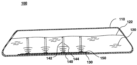
FIG. 1 illustrates an instrumented fuel-tank system, in accordance with
one embodiment of the present invention at 100. Fuel-tank system 100
comprises a fuel tank 110 containing fuel 120, a transducer carrier tape 130
with one or more ultrasonic transducers 140, and a separation barrier 150.
Fuel tank 110 is a containment vessel for fuel 120, which may include,
for example, gasoline, fuel oil, or jet fuel. In one embodiment for use in jet
aircraft, fuel tank 110 may, for example, hold 50 gallons of fuel or less for
use
in smaller, propeller-driven general aviation craft, or in excess of 10,000
gallons for larger commercial and military aircraft. Fuel tank 110 may be
located in a wing, a fuselage, or any suitable location within the aircraft.
Fuel
tank 110 may be filled or partially filled with fuel. A partially filled fuel
tank 110
may have a fuel-air surface 122 at the interface between fuel 120 and air or
other gaseous materials comprising the un-filled portion of fuel tank 110.
CA 02759068 2011-11-16
-5-
Various materials may be used to construct fuel tank 110 such as
composite materials including fiberglass or graphite epoxy. Fuel tank 110
may include a composite material. Composite materials typically include two
constituents: fibers and a matrix. High tensile-strength fibers are dispersed
throughout the matrix to provide additional strength, augmenting the
toughness and chemical inertness of the matrix material. Typical matrix
systems and fiber materials may include one of the following:
TYPICAL TYPES OF MATRIX (RESIN) SYSTEMS FOR COMPOSITES
Thermoset Matrix Resin:
= Bismaleimide
= Cyanate Ester
= Epoxy, 250 cure
= Epoxy, 350 cure
Toughened Epoxy
= Phelonic
= Polyester
= Polyimide
= Vinyl Ester
Thermoplastic Matrix resin:
= Liquid Crystal
= Polyamide
= Polyamide-imide
= Polyarylene Ketone, Sulfide
= Polyether Ketone Family (PEK, PEKK, PEEK)
= Polyetherimide
= Polyethersulfone
= Polyimide
= Polyphenylene Sulfide
CA 02759068 2011-11-16
-6-
TYPICAL TYPES OF FIBERS FOR COMPOSITES
Carbon Fibers from Precursors:
= Carbon Fiber from PAN
= Carbon Fibers from Pitch
= Carbon Fibers from Rayon
Organic Fibers:
= Aramid (Kevlar)
= Carbon, PAN -based
= Carbon, pitch-based
= Carbon, Rayon-based
= Polybenzimidazole
= Polyethylene
Inorganic Fibers:
= Structural high-strength Fiber Glass
= E- Fiber Glass
= Aluminum
= Boron
= Quartz
= Silicon Carbide
= Other Ceramics
The tanks may be a single piece and of unitary construction, or assembled
from several smaller pieces.
Transducer carrier tape 130 is coupled to a surface of fuel tank 110.
Transducer carrier tape 130 may be attached to or embedded in one of the
walls of fuel tank 110 such as the base or top. Transducer carrier tape 130
may be attached to the interior or the exterior of the tank. Transducer
carrier
tape 130 may be attached to a wall of the tank and covered with tank material
to embed it inside the tank wall. Transducer carrier tape 130 contains one or
more ultrasonic transducers 140 mounted or attached to the tape.
CA 02759068 2011-11-16
-7-
Transducer carrier tape 130 may comprise a flex circuit or a flex tape.
Transducer carrier tape 130 is generally a flexible tape or circuit,
containing
ultrasonic transducers 140 and one or more layers of electrical traces within
the tape. Transducer carrier tape 130 may be a flex circuit or a flex tape,
comprising ultrasonic transducers and interconnections on one or more metal
layers such as, for example, copper, aluminum or gold, separated by one or
more passivation layers such as, for example, polyimide. Flex tapes and flex
circuits are typically thin, multi-layer flexible circuit boards that contain
one or
more active or passive electronic devices, vias between metal layers, and
solder pads for attaching any active or passive electronic devices. The flex
tapes and flex circuits may be formed in various shapes such as short strips,
long strips, interconnecting strips, rectangular sections, circular segments,
or
any combination thereof. The transducers, interconnects, traces, connectors,
and any other circuit elements may be positioned on transducer carrier tape
130 as desired to provide indications of fuel height or fuel level.
Ultrasonic transducers 140 are positioned along transducer carrier tape
130 at one or more transducer pads. One or more ultrasonic transducers may
be located at each transducer pad. The location of ultrasonic transducers 140
is determined by the tank geometry and orientation of the tank in the
aircraft.
Ultrasonic transducers 140 may be located at one or more places in the tank,
such as the top and bottom, or various places along the bottom. Multiple
ultrasonic transducers 140 provide additional signals for more accuracy in
fuel-level determination, and add reliability and redundancy. Ultrasonic
transducers 140 may be positioned along the width or length of fuel tank 110
to provide multiple fuel-level measurements such that an average fuel-level
can be determined.
CA 02759068 2011-11-16
-8-
At least one ultrasonic transducer 140 emits and sends an ultrasonic
signal 142 into fuel 120. At fuel-air interface 122, the sound wave partially
reflects and the reflected ultrasonic signal or reflected signal 144 travels
back
through the fuel to ultrasonic transducers 140. Reflected signal 144 is
received by at least one ultrasonic transducer 140 to determine a fuel level
in
the fuel tank. Ultrasonic transducer 140, when deformed by reflected signal
144, typically generates a voltage or a charge. The generated voltage or
charge can be used to determine fuel level by an ultrasonic fuel-gauge
controller.
Separation barrier 150 may be disposed on transducer carrier tape 130
to cover or encase it, and to insulate or isolate transducer carrier tape 130
from fuel in the fuel tank. Separation barrier 150 also separates fuel 120
from
connective traces within transducer carrier tape 130. Separation barrier 150
may be placed on top of transducer carrier tape 130 after the tape is attached
to the inside or outside of the fuel tank. Separation barrier 150 may comprise
a composite material. Separation barrier 150 may be formed from the same
material used to form the tank, thereby embedding transducer carrier tape
130 within the tank wall. Ultrasonic emissions from ultrasonic transducers
140 may traverse a portion of the tank wall before propagating through fuel
120. The time required for traversing the walls of the tank may be subtracted
when determining the fuel level.
FIG. 2 shows an illustration of a transducer carrier tape with an
ultrasonic transducer for ultrasonic fuel-gauging measurements, in
accordance with one embodiment of the present invention at 200. Ultrasonic
fuel-gauging system 200 comprises a transducer carrier tape 230 and at least
one ultrasonic transducer 240. An ultrasonic fuel-gauging system controller
260 is shown connected to ultrasonic fuel-gauging system 200.
CA 02759068 2011-11-16
-9-
Transducer carrier tape 230 includes at least one layer of
interconnection wiring or traces 232, and at least one ultrasonic transducer
240 attached to the tape. Traces 232 provide electrical connections to
ultrasonic transducers 240 along the tape. Traces 232 may be located on one
or more metal layers of transducer carrier tape 230, formed by, for example,
patterning and etch steps, as is well known in the art. The traces may include
thin, narrow strips of copper, beryllium copper, nickel, tin, stainless steel,
aluminum or gold sandwiched between thin, insulative layers of polyimide,
polyester, mylar or other suitable polymeric material. One or more traces may
be connected to each ultrasonic transducer 240. Traces 232 may be
connected to each transducer on transducer carrier tape 230. Alternatively,
one or more traces such as, for example, a common drive signal or a common
ground may be connected in common to all the transducers along the tape.
An additional set of traces maybe included for the return signal, or the
return
signals may be sent back along the same set of traces used to drive the
transducers. Other active and inactive components such as termination
resistors and decoupling capacitors may also be mounted to transducer
carrier tape 230. Drive circuitry and signal conditioning circuitry configured
using standard or custom integrated circuits may be mounted on transducer
carrier tape 230, such as on a transducer pad in close proximity to each
ultrasonic transducer 240. Traces 232 may be used to connect ultrasonic
transducers 240 to controller 260.
Ultrasonic transducer 240 may include any suitable ultrasonic driver,
receiver, or driver/receiver pair, such as, for example, a piezoelectric disk.
The piezoelectric disk comprises a disk-shaped button of piezoelectric
material. Ultrasonic transducer 240 is comprised of a piezoelectric material
such as lead zirconate titanate (PZT), a lead-free piezoelectric ceramic,
quartz, zinc oxide, or a piezoelectric polymer such polyvinylidene fluoride
(PVDF). Electrical contacts are made to the top and bottom of the disk. At
least one ultrasonic transducer
CA 02759068 2011-11-16
-10-
240 is attached to transducer carrier tape 230. Ultrasonic transducers 240
may be attached to transducer carrier tape 230 and traces 232 using various
solders, conductive epoxies, and adhesives, as are known in the art.
A voltage applied across the piezoelectric material generates an
internal electric field and causes the piezoelectric material to contort.
Rapid
expansions and contractions of the piezoelectric material generate acoustic
waves. The generated acoustic waves or acoustic emissions propagate from
the ultrasonic transducer through any separation barrier or tank wall and into
the tank. The acoustic waves may traverse through the fuel or through the air
in the tank until a fuel-air surface is struck. A transmitted portion of the
acoustic wave continues in the same direction, whereas a reflection portion
returns back towards the ultrasonic transducer. When the reflected portion
strikes an ultrasonic transducer, a charge or voltage is generated by
mechanical deformations of the transducer. The signals may be sent directly
through traces 232 to controller 260, or the signals may be locally
conditioned
near the transducer and then sent to controller 260 or another suitable signal
processing system. An electrical connector and other electrical coupling
devices such as a wire harness or multi-conductor cable (not illustrated) may
be used to connect transducer carrier tape 230 to controller 260.
Controller 260 is operably connected to at least one ultrasonic
transducer 240. Controller 260 includes electronic circuitry and timing
circuitry to measure the transit time between the acoustic emission and the
reflected signal from at least one of the ultrasonic transducers. The transit
time or time-of-flight of the acoustic signal through the fuel or air in the
tank is
used to determine the fuel level. Fuel parameters such as the speed of the
acoustic sound waves in the media are applied to the transit-time data to
determine the fuel height or fuel level in the tank. Small changes in the
speed
of sound with fluid temperature or pressure may be compensated for with
controller 260. One or more temperature sensors may be included on
transducer carrier tape 230 such as near each
CA 02759068 2011-11-16
-11-
ultrasonic transducer to provide accurate, local measurements of fuel
temperature. Controller 260 provides output in any suitable digital or analog
format for display and recording, for example, in the cockpit of a commercial
or military aircraft equipped with a system of integrated fuel tanks.
FIG. 3 shows a block diagram of a method of determining fuel height or
fuel level in a fuel tank, in accordance with one embodiment of the present
invention at 300. Fuel-level determination method 300 comprises steps to
determine fuel level within an ultrasonic fuel-tank system.
An ultrasonic emission is sent from an interior surface of the fuel tank,
as seen at block 310. The ultrasonic emissions traverse any portion of the
fuel-tank wall and then propagate into the fuel or air in the fuel tank. One
or
more ultrasonic transducers mounted to or embedded within a wall of the fuel
tank may generate ultrasonic emissions. The ultrasonic transducers are
attached to a transducer carrier tape such as a flex circuit or a flex tape.
Ultrasonic transducers such as piezoelectric disks are electrically connected
to the flex circuit or flex tape. A plurality of ultrasonic transducers may be
positioned along a flex circuit or a flex tape. The flex circuit or flex tape
includes one or more layers of metallic interconnections. The transducer
carrier tape may be attached to or embedded within an interior surface or an
exterior surface of the tank wall. For example, the transducer carrier tape
may be attached to the bottom of the fuel tank and covered with a separation
barrier. Ultrasonic signals may be sent from one of a plurality of ultrasonic
transducers embedded in the base portion of the fuel tank. Alternatively, the
transducer carrier tape with a plurality of ultrasonic transducers may be
attached to or embedded in the top surface of the fuel tank, with ultrasonic
emissions propagating through any portions of the fuel-tank wall in front of
the
transducers and into the air in the fuel tank.
CA 02759068 2011-11-16
-12-
An ultrasonic emission from at least one ultrasonic transducer is
reflected from a fuel-air surface, and a reflected signal from the fuel-air
surface is received by at least one ultrasonic transducer to determine the
fuel
level in the fuel tank. The reflected signal may be received at one or more
ultrasonic transducers on the transducer carrier tape. The ultrasonic emission
may travel through the fuel to the fuel-air surface and back to the generating
transducer or other transducer along the transducer carrier tape.
Alternatively, the ultrasonic emission may travel through the air in the tank,
reflect off the fuel-air surface, and travel back to the generating transducer
or
another transducer on the transducer carrier tape. The ultrasonic emissions
may be generated and sent from one or more ultrasonic transducers on the
transducer carrier tape. A controller or other suitable electronic interface
may
be used to generate the drive voltages to initiate the ultrasonic emissions
from
the ultrasonic transducers.
A reflected signal is received from the fuel-air surface in the fuel tank,
as seen at block 320. The reflected signal may be received at. one or more
ultrasonic transducers along the transducer carrier tape. The ultrasonic
transducers generate a charge or a voltage when compressed or elongated
by the ultrasonic waves, and the charge or voltage is used to determine when
the reflected signal is received.
The transit time between the sent ultrasonic emission and the received
reflected signal is measured, as seen at block 330. The transit time, also
referred to as time-of-flight, is the time elapsed for an ultrasonic wave to
have
been sent from a transducer, traveled through the fuel and received back to
one or more transducers. The transit time may be measured for sound
propagation from one of a plurality of ultrasonic transducers to one of a
plurality of ultrasonic transducers along the transducer carrier tape.
Alternatively, the transit time may be measured for sound propagation
between one transducer and itself, or between one or more ultrasonic
transducer transceiver pairs. The transit time may be measured for sound-
wave propagation from one ultrasonic transducer to
CA 02759068 2011-11-16
-13-
multiple ultrasonic transducers. The transit time for sound-wave propagation
through any intervening fuel-tank wall material may be subtracted out or
calibrated out of the time-of-flight or transit time determination.
The fuel level of fuel within the fuel tank is determined based on the
sent ultrasonic emission and the received reflected signal, as seen at block
340. The fuel level may be determined by measuring the transit time between
the sent ultrasonic emission and the received reflected signal. The fuel level
may be determined by measuring one or more transit times between the sent
ultrasonic emissions and a plurality of received reflected signals from one or
more of ultrasonic transducers embedded in a base portion of the fuel tank.
In one embodiment, the fuel level is determined by multiplying the speed of
sound of the acoustic wave through the fuel by the transit time, and dividing
by two to account for two passages of the acoustic wave through the medium.
Other methods of fuel-level determination may be made from the transit times,
such as use of look-up tables or other suitable algorithms. Average fuel-
height measurements may be made from multiple consecutive transit time
measurements by averaging the transit-time measurements. and determining
the fuel level. The average transit time can then be multiplied by the speed
of
sound and divided by two to determine the fuel level. Alternatively, a look up
table or other algorithm may be used to determine fuel height. Alternatively,
the fuel level may be determined by averaging the transit times from more
than one transducer, and determining the fuel level from this average transit
time. Measurements from more than one ultrasonic transducer on the
transducer carrier tape may provide more accuracy, compensating for the
tank rolling and banking with turns, altitude adjustments, and shifts in
velocity
of the aircraft.
CA 02759068 2011-11-16
-14-
The fuel-height or fuel-level determinations may be made within a
controller containing a central processing unit, memory with microcode for
running the algorithm, and other software and hardware for determining fuel
level. The controller and its associated hardware and software can process
information from the fuel level determination into a suitable format for
display
and recording purposes. An indication of the fuel level may be output or
updated when the fuel level has been determined. Indications of fuel level
may be made by providing digital or analog signals from the controller that
indicate the fuel level in a format compliant with any applicable fuel system
standards.
Measurements of fuel level may be made with the controller and the
ultrasonic transducers on a continuous basis, at pre-determined times, upon
external request, or some combination thereof, by repeating blocks 310, 320,
330 and 340 accordingly.
Slight shifts in the speed of sound in a fluid occur with changes in
temperature. Temperature variations can affect the accuracy of the fuel-level
measurements. Compensation of fuel level can be made by measuring the
fuel temperature of fuel in the fuel tank, as seen at block 350, and
compensating the fuel-level determination based on the fuel temperature, as
seen at block 360. Fuel temperature may be measured directly with a
temperature sensor such as a thermocouple or resistive temperature device
(RTD) in the fuel tank, or inferred from temperature measurements at or near
the outside of the fuel tank. RTDs or other suitable temperature-sensing
devices may be included on the transducer carrier tape with the ultrasonic
transducers. The temperature-compensated fuel-level indication may be
output or updated accordingly. Additional measurements of fuel level are
possible by repeating blocks 310 through 360. Temperature-compensated
fuel level indications may be output on a continuous basis, at pre-determined
times, upon external request, or some combination thereof.
CA 02759068 2011-11-16
-15-
An approximation of the shape of the fuel tank may be determined
based on the sent ultrasonic emissions and the received reflected signals
from one or more ultrasonic transducers when the fuel tank is full of fuel, as
seen at block 370. The determined shape may be compared to a stored
shape of the fuel tank, as seen at block 380. Structural alterations of the
fuel
tank such as dents or bulges may be determined based on the determined
shape and the stored shape of the fuel tank, as seen at block 390. For
example, measures of transit times for each transducer representing the
shape of the tank may be made and stored when the tank is full of fuel. At a
subsequent time when the tank is again full of fuel, an additional set of
transit
times may be measured and compared to the stored values. A check may be
made to determine if any of the additional set of transit times is altered
appreciably from the stored values.
An indication of structural alterations may be output when the
determined shape and the stored shape materially differ. Alternatively, a
structural alteration indication may be output when it has been requested by
an external system or inquiry. Additional indications of structural
alterations
may be determined and output on a continual basis, at pre-determined times,
upon external request, or some combination thereof.
FIG. 4 shows a block diagram of a method of manufacturing a fuel tank
with an ultrasonic fuel-level measurement system, in accordance with one
embodiment of the present invention at 400. Fuel-tank manufacturing method
400 comprises steps to manufacture a fuel tank for an aircraft with an
integrated fuel-level measurement system.
CA 02759068 2011-11-16
-16-
A fuel-tank shell is provided, as seen at block 410. The fuel-tank shell
may be provided as a unitary piece, or in sections or segments that are
assembled together. The fuel-tank shell may be comprised of materials that
are strong, tough, non-metallic and chemically resistant to airplane and jet
fuels. The fuel-tank shell may comprise a composite material. Materials such
as graphite epoxy, fiberglass, and other suitable composite materials with
high-strength fibers in a tough matrix are typically used. Laminated sheets of
composite material with embedded fibers may be glued together and shaped
to form the tank walls. Uncured composite materials or composite materials
with an evaporative solvent may be spread upon or applied to a form or mold
of the tank, and dried or cured to provide a fuel tank with the desired shape
and strength.
A transducer carrier tape with one or more ultrasonic transducers is
positioned against a surface of the fuel-tank shell, as seen at block 420. The
transducer carrier tape comprises a flex circuit, a flex tape, or any suitable
flexible circuit board or tape. The ultrasonic transducers may be positioned
as
desired inside the tank or outside the tank, at the bottom of the tank or at
the
top of tank, or against any suitable surface of the fuel-tank shell.
The transducer carrier tape may be encased with a separation barrier,
as seen at block 430. The separation barrier may partially or fully encase the
carrier tape. The ultrasonic transducers may be covered with the separation
barrier or left exposed. The separation barrier may be formed from one or
more plies or layers of composite material. Each ply may be added on top of
the transducer carrier tape, suitably adhered, and dried or cured.
Alternatively, uncured composite material may be applied with any suitable
application means such as brushing, painting, spraying, dispensing or rolling,
and then dried or cured. Provision may be made for an electrical connector, a
slot for the transducer carrier tape, or other suitable structure to get the
electrical signals to and from the ultrasonic transducers.
CA 02759068 2011-11-16
-17-
While the embodiments of the invention disclosed herein are presently
preferred, various changes and modifications can be made without departing
from the spirit and scope of the invention. The scope of the invention is
indicated in the appended claims, and all changes that come within the
meaning and range of equivalents are intended to be embraced therein.