Note: Descriptions are shown in the official language in which they were submitted.
CA 02759362 2011-11-25
HORIZONTAL WELL LINE-DRIVE OIL RECOVERY PROCESS
FIELD OF THE INVENTION
The present invention relates to an oil extraction process, and more
particularly to a
method of extracting oil from subterranean hydrocarbon deposits using
horizontal wells.
BACKGROUND OF THE INVENTION
Steam-based oil recovery processes are commonly employed to recover heavy oil
and
bitumen. For example, steam-assisted-gravity-drainage (SAGD) and cyclic steam
injection are
used for the recovery of heavy oil and cold bitumen. When the oil is mobile as
native oil or is
rendered mobile by some in situ pre-treatment, the steam drive process may
also be used. A
serious drawback of steam processes is the inefficiency of generating steam at
the surface
because a considerable amount of the heat generated by the fuel is lost
without providing useful
heat in the reservoir. Roger Butler, in his book "Thermal Recovery of oil and
Bitumen', p.
415,416, estimates the thermal efficiency at each stage of the steam-injection
process as
follows: steam generator, 75-85%; transmission to the well, 75-95%' flow down
the well to the
reservoir, 80-95%; flow in the reservoir to the condensation front, 25-75%. It
is necessary to
keep the reservoir between the injector and the advancing condensation front
at steam
temperature so that the major energy transfer can occur from steam condensing
at the oil face.
In conclusion, 50% or more of the fuel energy can be lost before heat arrives
at the oil face. The
energy costs based on BTU in the reservoir are 2.6-4.4 times lower for air
injection compared
with steam injection. Several other drawbacks occur with steam-based oil
recovery processes:
natural gas may not be available to fire the steam boilers, fresh water may be
scarce and clean-
up of produced water for recycling to the boilers is expensive. In summary,
steam-based oil
recovery processes are thermally inefficient, expensive and environmentally
unfriendly.
There are many well patterns that can be employed for the production of oil
from
subterranean reservoirs. Some of these use vertical wells or combine vertical
and horizontal
wells. Examples of pattern processes are the inverted 7-spot well pattern that
has been
employed for steam, solvent and combustion-based processes using vertical
wells, and the
staggered horizontal well pattern of US Patent 5,273,111 which has been
employed (but limited
to) a process using steam injection.
-1-
CAL LAW\ 1738317\2
CA 02759362 2011-11-25
US Patent 5,626,191 discloses a repetitive method, termed "toe-to-heel" air
injection
(THAI TM ) , whereby a horizontal well is subsequently converted to an air
injection well to assist
in mobilizing oil for recovery by an adjacent horizontal well, which is
subsequently likewise
converted into an air injection well, and the process repeated.
US Patent 6,167,966 employs a water-flooding process employing a combination
of
vertical and horizontal wells.
US Patent 4,598,770 (Shu et at, 1986) discloses a steam-drive pattern process
wherein
alternating horizontal injection wells and horizontal production wells are all
placed low in a
reservoir. In situ combustion processes are not contemplated.
Joshi in Joshi, S. D., "A Review of Thermal oil Recovery Using Horizontal
wells", In Situ,
11(2 &3), 211-259 (1987), discloses a steam-based oil recovery process using
staggered and
vertically-displaced horizontal injection and production wells pattern. A
major concern is the high
heat loss to the cap rock when steam is injected at the top of the reservoir.
US Patent 5,273,111 (Brannan et at, 1993) teaches a steam-based pattern
process for
the recovery of mobile oil in a petroleum reservoir. A pattern of parallel
offset horizontal wells
are employed with the steam injectors. The horizontal sections of the
injection wells are placed
in the reservoir above the horizontal sections of the production wells, with
the horizontal
sections of the production wells being drilled into the reservoir at a point
between the base of
the reservoir and the midpoint of the reservoir. Steam is injected on a
continuous basis through
the upper injection wells, while oil is produced through the lower production
wells. In situ
combustion processes are not mentioned.
US Patent 5,803,171 (McCaffery et at, 1998) teaches an improvement of the
Brennan
patent wherein cyclic steam stimulation is used to achieve communication
between the injector
and producer prior to the application of continuous steam injection. In situ
combustion
processes are not mentioned.
US Patent 7,717,175 (Chung et al, 2010) discloses a solvent-based process
utilizing
horizontal well patterns where parallel wells are placed alternately higher
and lower in a
THAI", is a registered trademark of ARCHON Technologies Ltd. of Calgary,
Alberta for "Oil recovery services,
namely, the recovery of oil from subterranean formations through in-situ
combustion techniques
and methodologies and oil upgrading catalysts"
-2-
CALLAW\ 1738317\2
CA 02759362 2011-11-25
reservoir with the upper wells used for production of solvent-thinned oil and
the lower wells for
solvent injection. Gravity-induced oil-solvent mixing is induced by the
counter-current flow of oil
and solvent. The wells are provided with flow control devices to achieve
uniform injection and
production profiles along the wellbores., The devices compensate for pressure
drop along the
wellbores which can cause non-uniform distribution of fluids within the
wellbore and reduce
reservoir sweep efficiency. In situ combustion processes are not mentioned.
WO/2009/090477 (Xiai and Mauduit, 2009) discloses an in situ combustion
pattern
process wherein a series of vertical wells that are completed at the top are
placed between
horizontal producing wells that are specifically above an aquifer. This
arrangement of wells is
claimed to be utilizable for oil production in the presence of an aquifer.
US Patent Application 2010/0326656 (Menard, 2010) discloses a steam pattern
process
entailing the use of alternating horizontal injection and production wells
wherein isolated zones
of fluid egress and ingress are created along the respective wellbores in
order to achieve
homogeneous reservoir sweep. The alternating wellbores may be in the same
vertical plane or
alternating between low and high in the reservoir, as in US Patent 5,803,171.
Hot vapour is
injected in the upper wells (e.g. Steam).
Improved efficiency, shortened time on initial return on investment (ie
quicker initial oil
recovery rates to allow more immediate return on capital invested), and
decreased initial capital
cost, in various degrees, are each areas in the above methods which may be
improved.
SUMMARY OF THE INVENTION
An ideal oil recovery processes for recovering oil from an underground
reservoir has a
high sweep efficiency, uses a free (no cost) and infinitely available
injectant, requires no
purchased fuel, generates heat precisely where it is needed- at the oil face,
and scavenges
heat from the reservoir where heating of a reservoir was used . Additionally,
a high oil
production rate, especially in the initial stage of the exploitation, is
critical to the viability and/or
profitability of an oil recovery process.
The present invention, a horizontal well line-drive process for recovery of
oil from
hydrocarbon-containing underground reservoirs, has two advantages over a
"Staggered Well"
pattern configuration of oil recovery, the latter being a non-public method of
oil recovery
conceived by the inventor herein and more fully disclosed below, which
"Staggered Well"
-3-
CALLAW\ 1738317\2
CA 02759362 2011-11-25
method in many respects is itself an improvement, in certain respects and to
varying degrees,
over the above prior art methods and configurations.
Specifically, for a comparable volumetric sweep area and identical total
cumulative oil
recovery in regard to a hydrocarbon-containing subterranean reservoir
(formation), the
horizontal well line-drive (hereinafter "HWLD" ) process of the present
invention has been
experimentally shown, as discussed herein, to provide a greater initial rate
of recovery of oil
than the "Staggered Well" method discussed herein. Thus a greater and more
rapid initial
return on investment for oil companies incurring large expenditures in
developing subterranean
reservoirs may be achieved. This is a significant advantage , since investment
in developing oil
reservoirs is very high, and the time in which a return on investment may be
realized is
frequently a very real and substantial consideration as to whether the
investment in such a
capital project is ever made in the first place.
In addition, the horizontal well line-drive process of the present invention,
for a
comparable volumetric sweep area and near identical total
oil recovery, has been
experimentally shown to require fewer wells than the "Staggered Well"
configuration, thus
significantly reducing the capital costs to an oil company to develop and
produce oil from an
underground hydrocarbon-containing formation.
Accordingly, by way of broad summary, in one broad embodiment of the HWLD oil
recovery process of the present invention, a first horizontal well is drilled
high in a subterranean
hydrocarbon-containing reservoir, and a medium such as a gas is injected into
the reservoir via
perforations in a well liner in such first horizontal well. Oil, water and gas
are co-produced via a
second parallel laterally offset horizontal well, placed low in the reservoir.
When the oil rate at
the second horizontal (production) well falls below an economical limit, a
third parallel
horizontal well is drilled low in the reservoir laterally spaced apart from
the second horizontal
well, and used to produce oil, while at the same time the second horizontal
well (initially a
production well) is converted to an injection well, and such gas likewise
injected into the
formation via such second horizontal well so as to allow the combustion front
to be continually
supplied with oxidizing gas to permit continued progression of the combustion
front and thus
continued heating of oil ahead of the advancing combustion front, which drains
downwardly and
is collected by the horizontal wells drilled low in the formation ahead of (or
at least below) the
advancing combustion front . The steps of drilling further horizontal,
parallel, laterally spaced
apart wells low in the formation , and successively converting 'exhausted"
production wells to
injection wells to further the recovery of oil from remaining production wells
is continued in a
-4-
CAL _LAW \ 1738317\2
CA 02759362 2011-11-25
substantially linear direction along the reservoir in order to exploit the
reservoir in a single
direction as a line-drive-process' that achieves high reservoir sweep
efficiency. The injectant, if
a gas, may be a solvent gas such as CO2 or light hydrocarbon or mixtures
thereof, steam or an
oxidizing gas such as oxygen, air or mixtures thereof. Alternatively the
injectant may be any
mixture of solvent, steam or oxidizing gas. A favoured embodiment utilizes
steam injectant and
the most favoured embodiment utilizes oxidizing gas as the injected medium.
When the process utilizes oxidizing gas injectant and in situ combustion, it
meets the
commercial needs of relatively low energy costs and low operating costs by
providing a novel
and efficient method for recovering hydrocarbons from a subterranean formation
containing
mobile oil.
The distance between the parallel and offset horizontal well producers, as
well as the
well lengths, will depend upon specific reservoir properties and can be
adequately optimized by
a competent reservoir engineer. The lateral spacing of the horizontal wells
can be 25-200
meters, preferably 50-150 meters and most preferably 75-125 meters. The length
of the
horizontal well segments can be 50-2000 meters, preferably 200-1000 meters and
most
preferably 400-800 meters.
In a homogeneous reservoir using the method of the present invention it is
beneficial
for high reservoir sweep efficiency to deliver the injectant equally to each
perforation in the
injection well liner and to compel equal fluid entry rates at each perforation
at each perforation in
the production well liner. Considering that horizontal wells typically have a
`toe' at the end of
the horizontal segment, and a 'heel' where the horizontal segment joins the
vertical segment, in
a refinement of the present invention it is preferred to place the horizontal
wells so that the heel
of the injector (injection) well is opposite the toe of the adjacent laterally
spaced apart producer
(production) well so that "short-circuiting" of gas between injector and
producer wells is
minimized. Short circuiting otherwise occurs because the point of highest
pressure in the
injector well is at the heel since a pressure drop is typically incurred as
the injectant is pumped
under pressure and flows along the horizontal leg from heel to toe.
Conversely, the point of
highest pressure in a producer (production) well is at the toe, as gas and oil
is typically drawn
from the heel. Accordingly, it is preferred to have the heel of the injector
well opposite the toe of
the adjacent production well, so that high pressure (typically heated) gas is
forced to travel a
greater distance through the formation to the low pressure portion at the heel
of the adjacent
production well.
-5-
CALLAW \ 1738317\2
CA 02759362 2011-11-25
Alternatively, both the injection and production wells may be placed with the
respective
heel and toe portions in mutually juxtaposed position. In such case it is then
preferred to use
internal tubing to inject the gas at the toe of the injection well , thereby
moving the high pressure
source from the heel of the injection well to its toe. In such manner the high
pressure source
will be at an end of the reservoir opposite the low pressure heel of the
production well, thereby
forcing the gas to travel a longer distance through the formation and thereby
more effectively
free oil trapped in the formation , so as to then travel and be collected by
the low pressure area
at the heel of the production well. Such configuration has the benefit of
requiring only a single
drilling pad located on the same side of the reservoir, since the vertical
portion of the injector
wells and the producer wells will all be on the same side of the reservoir.
In addition to the employment of configurations which transpose (reverse) the
respective
heel and toe portions of adjacent horizontal wells or alternatively use
internal tubing in the
injector well, the uniform delivery of gas along the length of the injection
well and uniform
collection of oil along the production well may be obtained, or further
enhanced, by varying the
number and size of perforations along the well liner in an injector well, to
balance the pressure
drop along the well. A pressure-drop-correcting perforated tubing can be
placed inside the
primary liner of the injector well. This has the advantage of utilizing gas
flow in the annular
space to further assist the homogeneous delivery of gas. Alternatively, or in
addition, similar
methodologies may be applied to the production wells in order to more
uniformly collect mobile
oil along substantially the entire length of the production well, and assist
in preventing "fingering"
of injectant gas directly into production wells.
The outside diameter of the horizontal well liner segments can be 4 inches to
12 inches,
but preferably 5-10 inches and most preferably 7-9 inches. The perforations in
the horizontal
segments can be slots, wire-wrapped screens, Facsritetm screen plugs or other
technologies
that provide the desired degree of sand retention.
The injected gas may be any oxidizing gas, including but not limited to, air,
oxygen or
mixtures thereof.
Facsriterm is an unregistered trademark of Absolute Completion Technologies
for well liners having sand screens
therein
-6-
CAL LAW\ 1738317\2
CA 02759362 2011-11-25
It is desirable to achieve equal gas injection rates along the injector well
and equal fluid
production rates along the horizontal production well in order to obtain the
greatest reservoir
sweep efficiency and uniform recovery. The maximum gas injection rate will be
limited by the
maximum gas injection pressure, which must be kept below the rock fracture
pressure, and will
be affected by the length of the horizontal wells, the reservoir rock
permeability, fluid saturations
and other factors.
The use of a numerical simulator such as that used in the Examples below is
beneficial
for confirming the operability and viability of the design of the present
invention for a specific
reservoir, and can be readily conducted by reservoir engineers skilled in the
art.
Accordingly, and more particularly, in a first broad aspect of the method of
the present
invention, such method is directed to a method for recovering oil from a
hydrocarbon-
containing subterranean reservoir, comprising the steps of:
(i) drilling a first horizontal well, situated relatively high in said
reservoir;
(ii) drilling a second horizontal well, situated relatively low in said
reservoir and
aligned substantially parallel to said first horizontal well;
(iii) injecting a medium comprising a gas, steam, or a liquid into said
reservoir via
apertures in said first horizontal well ;
(iv) withdrawing oil which moves downwardly in said subterranean reservoir and
flows
into said second horizontal well, from said second horizontal well;
(v) drilling a third horizontal well, relatively low in said reservoir and
substantially parallel
to said first and second horizontal wells but laterally spaced apart
therefrom, laterally
spaced farther from said first horizontal well than from said second
horizontal well;
(vi) temporarily or permanently ceasing withdrawing hydrocarbons from said
second
horizontal well and
proceeding to inject a second medium comprising a gas, steam,
or a liquid into said second horizontal well; and
(vii) withdrawing oil which moves downwardly in said subterranean reservoir
into said
third horizontal well, from said third horizontal well.
-7--
CALLAW\ 1738317\2
CA 02759362 2011-11-25
Each of said second , third, and further subsequently- drilled horizontal
wells are all
preferably co-planar with each other, but not with said first well, and
laterally spaced from one
another.
In order to make use of the "line drive" aspect of the invention and allow a
sweeping of a
significant volume of oil from within a substantially-sized hydrocarbon-
containing reservoir,
such method further comprises additional repeated steps to allow a progressive
"sweep" in a
generally linear direction along said formation, including the further steps
of:
successively drilling additional horizontal wells low in said reservoir
substantially
parallel to and substantially co-planar with the third horizontal well but
laterally spaced apart
therefrom and from each other; and
successively converting penultimate wells of said additional horizontal wells
from a
production well to an injection well for injecting said gas, steam, or a
liquid so as to cause oil
in said reservoir to move from within said reservoir downwardly into a last of
said additional
horizontal wells.
In a preferred embodiment, the first medium and the second medium are one and
the
same medium. In a further preferred embodiment, such medium is a gas which is
soluable in
the oil. Alternatively, the medium is a gas, namely CO2, light hydrocarbons,
or mixtures
thereof.
In yet a further preferred embodiment such medium comprises oxygen gas, air,
or
mixtures thereof for the purpose of conducting in situ combustion, and said
method further
comprises the step , after step (iii) , of igniting hydrocarbons in the
reservoir in a region
proximate the first horizontal well, and withdrawing oil and combustion by-
products from the
subterranean formation via the second well and /or simultaneously or
subsequently via the
third well. The step of igniting the hydrocarbons and withdrawing combustion
by-products
and oil via said second horizontal well and/or said third horizontal well
causes a combustion
front to move laterally from said first horizontal well in the direction of
said second and third
horizontal wells, thereby heating oil in said reservoir and causing said oil
to drain downwardly
for collection by said second and/or third horizontal wells.
Accordingly, in a most preferred embodiment of the HWLD method of the present
invention for recovering oil from a hydrocarbon-containing subterranean
reservoir, such method
comprises:
-8-
CALLAW\ 1738317\2
CA 02759362 2011-11-25
(i) drilling a first horizontal well relatively high in said reservoir, having
a plurality of
apertures along a length of said first well;
(ii) drilling a second horizontal well relatively low in said reservoir and
substantially
parallel to said first horizontal well;
(iii) injecting an oxidizing gas into said first horizontal well and into said
reservoir via
said apertures, for purposes of conducting in situ combustion in said
reservoir;
(iv) igniting hydrocarbons in said reservoir ;
(v) withdrawing oil which drains downwardly in said subterranean reservoir
into said
second horizontal well from said second horizontal well;
(vi) drilling a third horizontal well, relatively low in said reservoir and
substantially parallel
to said second horizontal well but laterally spaced apart therefrom and
laterally spaced from
said first injection well farther than from said second injection well;
(vii) temporarily or permanently ceasing producing hydrocarbons from said
second
horizontal well ;
(viii) injecting said oxidizing gas into said second horizontal well; and
(ix) withdrawing oil which drains downwardly in said subterranean reservoir
into said
third horizontal well, from said third horizontal well.
Where oxidizing gas is used as the injected medium, for the purposes of
conducting in
situ combustion, combustion ignition (ie step (iv) above) can be accomplished
by various means
well known to those skilled in the art, such as pre-heating the near-wellbore
oil with hot fluids
such as steam or the injection of spontaneously ignitable fluid such as
linseed oil prior to
injection of oxidizing gas. In this case, hot nitrogen (400 C.) was injected
at the rate of 16,667
m3/d for one month prior to switching to air at 100 C. The air does not have
to be heated at the
surface: it is heated by the act compression.
As mentioned above, to ensure high pressure ends of an injector well are not
situated
immediately adjacent the lowest pressure point (ie the heel portion) of an
adjacent producer well
thus giving rise to "short circuiting" or "fingering" of high pressure gas
directly to the heel portion
of the production well, in a preferred embodiment said step (iii) of injecting
a gas, steam, or
liquid into said first horizontal well comprises the step of injecting said
gas, steam, or liquid
-9-
CALLAW\ 1738317\2
CA 02759362 2011-11-25
into one end of said first horizontal well, and said step of withdrawing oil
from said second
horizontal well comprises the step of withdrawing said oil from one end of
said second well ,
said one end of said second well situated on a side of said reservoir opposite
a side thereof at
which said one end of said first horizontal well is situated. Such
configuration allows more
uniform injection of such gas into the formation and reduces (and preferably
avoids) "fingering"
("short-circuiting") of high pressure gas directly from the injector well to
the production well.
Such approach may likewise be adopted not only with regard to the first and
second
wells, but also with regard to the second well relative to the third, and so
on. For example, with
regard to the arrangement of the second well relative to the third well, said
step of injecting
said gas, steam, or liquid into said second horizontal well may comprise the
step of injecting
said gas, steam, or liquid into an end of said second horizontal well situated
on a side of said
reservoir opposite an end of said third horizontal well from which said oil is
collected from. In
other words, proximal ends of mutually adjacent wells may be situated on
mutually opposite
sides of said reservoir.
Alternatively , the first end of each of the second well and third well may be
situated on
the same side of the reservoir. In such case, to reduce or avoid the
"fingering" problem, said
step of injecting said gas, steam, or liquid into said second horizontal well
comprises injecting
said gas, steam, or liquid into a second end of said second well via tubing,
which tubing
extends internally within said second well substantially from said first end
to said second end of
said second well.
Alternatively, where a first end of each of said second and third horizontal
wells are
located on a same side of said reservoir, said step of injecting said gas,
steam, or liquid into
said second horizontal well may comprise injecting said gas, steam, or liquid
into said first end
of said second well, and said step of withdrawing oil from said third well
comprises withdrawing
such oil from a second end of said third well via tubing , said tubing
extending internally
within said third well from said first end to substantially said second end of
said third well.
Alternatively, or in addition, to avoid or reduce "fingering" of high pressure
gas from an
injection well to a production well, such as from the first horizontal
injector well to the second
well when such second well acts as a producer well, in one embodiment the
first horizontal
well has a well liner in which said plurality of apertures are situated, and a
size of said
apertures or a number of said apertures within said liner within said first
horizontal well
progressively increase from a first end to a second end of said first
horizontal well.
-10-
CAL_LAW\ 1738317\2
CA 02759362 2011-11-25
Likewise, progressive increase in aperture size or number of apertures along
the length
of well liners in each of second, third, or subsequent wells may likewise be
utilized. In such
manner , by having larger or more numerous apertures at one end of a well than
at another ,
pressure (and thus flow) can be more uniform over the length of the well, or
even made higher
at one end than another, and provided an adjacent well similarly employs
progressive variation
in an opposite direction, direct "short-circuiting " of gas from an injector
well to an adjacent
production well can be reduced or avoided. Instead, cross-flow of gas through
the formation is
thereby inducted to better expose the (typically high temperature) gas to more
oil in the
formation, thus increasing recovery rate of oil from the formation.
BRIEF DESCRIPTION OF THE DRAWINGS
In the accompanying drawings, which illustrate one or more exemplary
embodiments
and are not to be construed as limiting the invention to these depicted
embodiments:
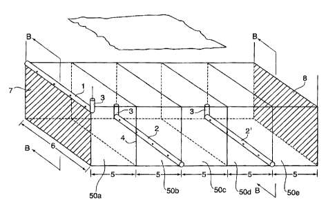
Fig. 1 shows a perspective schematic view of a subterranean hydrocarbon-
containing
reservoir of the "staggered well " configuration, having a plurality of
horizontal injection wells
located high in the reservoir and a plurality of alternatingly-spaced
horizontal production wells
situated low in the reservoir;
Fig. la shows a similar perspective schematic view of a subterranean
hydrocarbon-
containing reservoir of the "staggered well " configuration, to show the model
used in Example
1 of the computer simulation , and which produced the experimental test
results (line "B") of
Fig. 5;
Fig. 2 (i)-(iii) are views on section A-A of Fig. 1, at various time
intervals, showing a
variation of the Staggered Well method of producing oil, which may optionally
use a line drive
of oil recovery in the direction of arrow "Q;
Fig. 3 shows a perspective schematic view of a subterranean hydrocarbon-
containing
reservoir of the horizontal well line drive ("HWLD") configuration of the
present invention,
having a first horizontal well located high in the reservoir, and a plurality
of spaced horizontal
production wells situated low in the reservoir;
CALLAW\ 1738317\2
CA 02759362 2011-11-25
Fig. 4a (i) ¨(iii) are views on section B-B of Fig. 3, at successive time
intervals,
showing a method of producing oil using such "horizontal well line drive"
configuration, showing
the method for causing a line drive of oil recovery in the direction "Q;
Fig. 4b (i) ¨(iii) are views on section B-B of Fig. 3, at successive time
intervals,
showing a modified method of producing oil using such "horizontal well line
drive"
configuration, showing the method for causing a line drive of oil recovery in
the direction "Q;
Fig. 4c (i) ¨(iv) are views on section B-B of Fig. 3, at successive time
intervals,
showing a further variation of the method of producing oil using such
"horizontal well line drive"
configuration, showing the steps for causing a line drive of oil recovery in
the direction "Q;
Fig. 5 is a graph of cumulative oil recovery versus time (years), comparing
cumulative
oil recovery of the "staggered well" method of recovery shown in Fig.'s 1 & 2
(line "B" of Fig.
5), to the cumulative oil recovery obtained using the "horizontal well line
drive" method of the
present invention shown in Fig. 4b (i)-(iii), for a reservoir having the
horizontal well locations
and configuration shown in Fig. 11 (line "A" of Fig. 5);
Fig. 6 is a perspective schematic view of a subterranean hydrocarbon-
containing
reservoir of the "horizontal well line drive " configuration of the present
invention similar to Fig.
3;
Fig. 7 is a view on a modification to the parallel, mutually adjacent but
spaced-apart
horizontal injection (production) wells of Fig. 6, showing two of such
horizontal mutually-
adjacent wells, wherein in a further embodiment tubing is used to deliver a
medium such as an
oxidizing gas to a "toe" (ie distal) end of the horizontal injection well;
Fig. 8 is a view on a modification to the parallel, mutually adjacent but
spaced-apart
horizontal injection (production) wells of Fig. 6, showing two of such
horizontal mutually-
adjacent wells, wherein in a further embodiment tubing is used to recover oil
from a "toe" (ie
distal) end of the horizontal production well;
Fig. 9 is a view of an alternative modification to the parallel, mutually
adjacent but
spaced-apart horizontal injection (production) wells of Fig. 6, showing two of
such horizontal
mutually-adjacent wells, wherein apertures therein are more closely spaced and
more
numerous towards the "toe" (ie distal) end of each of such horizontal wells;
-12-
CALLAW\ 1738317\2
CA 02759362 2011-11-25
Fig. 10 is a view of a further alternative modification to the parallel,
mutually adjacent
but spaced-apart horizontal injection (production) wells of Fig. 6, showing
two of such
horizontal mutually-adjacent wells, wherein apertures therein are larger
towards the "toe" (ie
distal) end of each of such horizontal wells;
Fig. 11 is a perspective schematic view of a subterranean hydrocarbon-
containing
reservoir similar to Fig. 6, showing a modified "horizontal well line drive"
configuration of the
present invention , and which configuration produced the experimental test
results (line "A") of
Fig. 5;
Fig. 12 is a view of a modification to the parallel, mutually adjacent but
spaced-apart
horizontal injection (production) wells of Fig. 11, showing two of such
horizontal mutually-
adjacent wells , wherein apertures therein are larger towards the "toe" (ie
distal) end of each of
such horizontal wells; and
Fig. 13 is a view of a modification to the parallel, mutually adjacent but
spaced-apart
horizontal injection (production) wells of Fig. 11, showing two of such
horizontal mutually-
adjacent wells , wherein apertures therein are more numerous and more closely
spaced
towards the "toe" (ie distal) end of each of such horizontal wells.
DETAILED DESCRIPTION OF PREFERRED EMBODIMENTS
Fig.'s 1 &
la show a developed hydrocarbon-containing subterranean
formation/reservoir 22 of the "staggered well" (hereinafter "Staggered Well"
configuration) ,
which does not form part of the invention claimed herein but forms subject
matter of another
application of the undersigned inventor, such other application being commonly
assigned with
the present invention.
In such "Staggered Well" configuration, parallel horizontal injection wells 1,
1', & 1" of
each of length 6 are placed parallel to each other in mutually spaced
relation, all situated high
in a hydrocarbon-containing portion 20 of subterranean formation/reservoir 22
of thickness 4,
situated below ground-level surface 24. Parallel horizontal , spaced apart
production wells 2, 2'
& 2" of similar length 6 are respectively placed low in the reservoir 22,
midway between
respective injection wells 1, 1', and 1", to make a well pattern array of
staggered and laterally
separated parallel and alternating horizontal gas injection wells 1, 1', & 1"
and fluid production
wells 2, 2' & 2", as shown in Fig. 1 and 1a..
-13-
CALLAW\ 1738317\2
CA 02759362 2011-11-25
The hydrocarbon-containing reservoir 22 shown in Fig. 1 possesses two and one-
half
injection wells 1, 1', & 1" (edge injection well 1 and edge production well 2"
each respectively
constituting one-half well) for a total of five horizontal wells in the
pattern. Conducting three
repetitions of the method of Fig. 1 requires fifteen horizontal wells, as
shown in Fig. la.
The lateral spacing 5 of the injection wells 1, 1', & 1" and production wells
2, 2' & 2" is
preferably uniform.
In a preferred embodiment shown in Fig.'s 1, la, the vertical segments 8 of
the
horizontal injection wells 1, 1' & 1" are at opposite ends compared with the
vertical segments 9
of the horizontal production wells 2, 2' & 2". The vertical segments 8 of the
injection wells 1, 1',
& 1" are offset by the well width 6 from the vertical segments 9 of the
production wells. This is
to minimize short-circuiting of injection gas into the production wells 1, 1',
& 1" as explained
above. The pattern shown can be extended indefinitely away from the face 3
and/or the face 6
as desired to cover a specific volume of oil reservoir 22. For example, for a
channel deposit the
pattern could extend across the width of the channel. In additional phases of
reservoir 22
development, additional arrays are placed adjacent to the first array, and so
on, eventually
exploiting the entire reservoir 22.
Referring to Fig. 1, a preferred embodiment of the invention horizontal
injector wells 1,
1' & 1" and production wells 2, 2' & 2" which are simultaneously drilled, each
possess well
liner segments 30 situated in each of horizontal wells 1, 1', & 1" and 2, 2' &
2" which
contain apertures 24, from which a medium such as an oxidizing gas, air,
oxygen alone or in
combination with carbon dioxide or steam, steam alone, or a diluent such as a
hydrocarbon
diluent , or combinations thereof, may be injected into the hydrocarbon-
containing portion 20
via an injector well 1, 1', & 1" , and through which oil may be allowed to
flow through to collect
in a horizontal production well 2, 2' & 2". In the case of horizontal
production wells 2, 2' & 2",
such well liners 30 and the apertures 24 therein may take the form of slotted
liners, wire-
wrapped screens, Facsrite" screen plugs , or combinations thereof, to reduce
the flow of sand
and other undesirable substances such as drill cuttings , from within the
formation 22 into the
production wells 2, 2' & 2".
In the "Staggered Well" configuration of Fig. 1, la, & 2, a medium such as an
oxidizing
gas, air, oxygen alone or in combination with carbon dioxide or steam, steam
alone, or a
diluent such as a hydrocarbon diluent , or combinations thereof, is injected
into formation 22
via apertures in horizontal injector wells 1, 1', & 1", to cause mobility of
oil in the oil-containing
-14-
CALLAW\ 1738317\2
CA 02759362 2011-11-25
portion 20 of formation 22. Such oil flows downwardly within formation 22, and
is collected in
horizontal collector wells 2, 2' & 2".
The Staggered Well method, in one embodiment, may alternatively utilize a line
drive
configuration, such method shown in Fig. 2 (i)-(iii), in which three phases
are implemented. In
this regard, Fig. 2 shows views on section A-A of Fig. 1, at successive
respective time
intervals (i), (ii), & (iii), showing a method of causing a line drive of oil
recovery in the direction
"Q" using such "Staggered Well" configuration. Specifically, as seen from the
first phase [Fig.
2 (I)], the injector well 1, and producer well 2 and 2' are first drilled, and
production from wells
2 and 2' commenced. Thereafter in a second phase [Fig. 2(ii)] , a third
injector 1" and a third
producer 2" are drilled, and injection and production commenced respectively
in regard to such
wells. In a third phase, a fourth injector 1" and a fourth producer 2" are
drilled, with production
ceasing from production well 2, and injection and production commenced in
injection well 1"
and production well 2" respectively. The process may be continued indefinitely
as shown in
Fig. la , until reaching an end of reservoir 22
Alternatively, as mentioned above, such "Staggered Well" method may simply
consist of
simultaneously drilling a set number of injector wells (eg. such as three
wells 1, 1', & 1") and
a corresponding number of producer wells (eg. such as three wells 2, 2' & 2")
so as to produce
the "pattern" of staggered wells of wells 1, 1', & 1" and 2, 2' & 2" shown in
Fig. 1. Such
pattern may be repeated as necessary, as shown in Fig. la. This method was
used in the
Examples (discussed below), for comparing the HWLD configuration and method to
the
Staggered Well configuration, using simultaneous drilling of five wells as
discussed above.
Fig's. 3, 6 & Figs. 4a-4c shows an alternative well arrangement /
configuration (Fig. =
3,6) and method (Figs. 4a-4c) for recovery of oil from a reservoir 22, namely
the horizontal
well line drive ("HWLD") configuration and method respectively of the present
invention, to
develop an oil bearing portion 20 of a reservoir 22 of a thickness 4, a width
6, and which
comprises a plurality of segments 50a-50o each of length 5 consecutively
positioned
commencing from plane 7 and progressing to the right of the page, as shown in
Fig's 3 and 6.
In such HWLD configuration and method, a first horizontal injection well 1 is
drilled high
within oil-containing portion 20 of reservoir 22, along edge 7, and a second
parallel horizontal
well 2 is drilled low in oil-containing portion 20 of reservoir 22, laterally
spaced apart from first
injector well I.
Horizontal wells 2 & 2' have vertical portions 3 at each of their respective
heel portions
-15-
CAL_LAW \ 1738317\2
CA 02759362 2011-11-25
42 which extend to surface 24. The distance separating planes 7 and 8
represent the edges of
the oil-swept volume of oil containing portion 20 of reservoir 22 in a first
phase of the method of
the present invention.
In the embodiment of the HWLD method shown in Fig. 11, the position of
vertical
segment 3 of first injection well 1 is offset by the well length 6 from the
vertical segments 3 of
the production wells 2 & 2'. This is to minimize short-circuiting of injection
gas into the
production wells as explained above. The pattern shown can be extended
indefinitely away from
the face 7 and/or the face 8 as desired to cover a specific volume of oil
reservoir 22. For
example, for a channel deposit it could extend across the width of the
channel. In additional
phases of development of reservoir 22 as shown for example in Fig. 6,
additional wells 2", 2",
2i" are drilled, laterally offset from the earlier drilled horizontal well 2',
so as to eventually exploit
the entire reservoir 22 along a length thereof.
Figs. 4a-c, namely in various alternative sub-phases (i),(ii), (iii), and (iv)
thereof, each
show the residual oil in oil containing portion 20 which is remaining after
each sub-phase of the
method of the present invention, in shaded portion.
In a first phase of the method of the present invention [identical in each of
various
methods shown in Fig. 4a (i), Fig. 4b(i), and Fig. 4c(i)] , gas is injected
into horizontal well 1
and oil is produced via second horizontal well 2 . In a second phase of the
method of the
present invention [ shown in . Fig. 4a , Fig. 4b, and Fig. 4c as step (ii)] ,
a third horizontal
well 2' is drilled low in the oil-containing portion 20 of reservoir 22,
parallel to horizontal well 2
but laterally spaced apart therefrom, and spaced laterally further from first
well 1 than from well
2, and production of oil carried out via well 2'. Upon the oil rate being
produced from second
horizontal well 2 diminishing to below an economical limit , production from
such well 2 is
ceased, and well 2 is then employed for gas injection, as shown in Figs. Fig.
4a (ii), Fig. 4b(ii),
and Fig. 4c(ii) . Gaseous injection via well 1 may continue during this phase,
or may cease as
shown in step (ii) of Fig.'s 4 a-c.
In a preferred embodiment, where vertical ends 3 of production well 2, 2' are
on the
same side of reservoir 22 as shown in Fig.3, gas injection in second
horizontal well 2 during
this second phase is preferably via an internal tubing 40 extending from a
proximal end (heel)
42 of third well 2' to the distal end (toe) 44 of well 2', with an open end
thereof being at distal
end 44 as shown in Fig. 7. Alternatively, if injection of gas into second well
2 is simply into a
proximal end 42 of injection well 2' (le no tubing 40 in injection well 2
during injection) , then
-16-
CAL LAW\ 1738317\2
CA 02759362 2014-01-20
internal tubing 40 may instead be provided in adjacent third well 2' when such
well 2' is acting
as a production well, and oil is thereby drawn from toe portion 44 of such
third well 2' via such
tubing 40, as shown in Fig. 8. As explained above, each of the alternative
configurations of Fig.
7 and Fig. 8 assist in avoiding "fingering" or "short circuiting of
pressurized gas from injection
well 2 directly to production well 2', when a configuration such as shown in
Fig. 3 is used
wherein each of the vertical portions 3 of production wells 2, 2', and 2" are
each on the same
side of reservoir 22. As noted above, in this second phase a new parallel
third well 2' is drilled
low in the reservoir and placed on fluid production [see Fig. 4a(ii), Fig.
4b(ii) and Fig. 4c(ii)].
During this second phase a fourth horizontal well 2" may be drilled, as shown
in Fig. 4a(ii) and
production initiated from such well 2" as well as from well 2'. Alternatively
only the drilling of well
2" may be conducted during this phase, with production from well 2" occurring
during the third
phase (discussed below) and as shown in Fig. 4c(iii) and (iv).
Figs. 4a(iii), 4b(ii9, and 4c(iii) each show slightly different third phases
of the method of
the present invention.
As regards the embodiment of the method disclosed in Fig. 4(b) (iii), when the
rate of oil
production from third well 2' being produced in step (i1) drops below a pre-
determined limit, a
drawdown phase is undertaken where gas is again injected in well 1. Well 2 is
switched back to
operating as a production well, and wells 2 and 2' are employed as production
wells for a time
to withdraw all remaining oil.
Thereafter the fourth well 2" may be drilled, and a similar process repeated
wherein a
former production well (well 2') is converted into an injection well 2', and
production commenced
from fourth well 2", while gas continues to be injected via well 1.
Alternatively, as regards the third phase shown in step (iii) of Fig. 4a,
injection of gas
from well 1 is ceased, with gas being injected into the reservoir 22 solely
via such well 2' which
as noted above is converted from a production well to an injection well.
Fourth well 2" operates
as a production well.
Alternatively, as shown in Fig. 4c(iii), injection of gas into well 1 may be
re-instituted to
completely drain all oil above wells 2 and 2', and a new fourth well 2"
drilled. Only thereafter,
when production from wells 2 and 2" is exhausted or substantially exhausted,
is well 2'
converted to an injector well and gas subsequently supplied to the formation
via well 2' and
production commenced from well 2" as shown in Fig. 4c(iii).
-17-
CALLAW\ 2051600\2
CA 02759362 2011-11-25
As noted above, where the vertical portions 3 of wells 2, 2', 2", 2", and 2 iv
are all
situated on the same side of reservoir 22 (see Fig. 6) and not on alternating
sides of reservoir
22, in order to reduce "fingering" between a mutually adjacent
collector/production well and a
mutually-adjacent injector well, tubing may be employed in the manner
described above and as
shown in Fig's 7 or 8.
As an alternative configuration to reducing or avoiding the "fingering" or
short-circuiting
problem between an injector and mutually-adjacent production wells 2, 2', 2" ,
2", 2iv having
respective vertical portions 3 of such wells on the same side of reservoir 22
as shown in Fig. 6
and to more uniformly inject gaseous medium such as oxidizing gas, steam,
carbon dioxide,
hydrocarbon diluents (in either gaseous or liquid form) in one embodiment
shown in Fig. 9, the
number of apertures 24 may be progressively made more numerous over the length
of
horizontal well 2, and similarly over the length of a mutually adjacent well
2', progressing from
the proximal end 42 toward the distal end 44 of each of said wells 2, 2', 2" ,
2", 2iv, and so
forth.
Alternatively, to likewise more uniformly inject gaseous medium such as
oxidizing gas,
steam, carbon dioxide, hydrocarbon diluents (in either gaseous or liquid form)
along the length
of an injector well (e.g. 2') and also to more uniformly collect oil along a
length of a mutually
adjacent collector well (e.g. 2"), in an embodiment shown in Fig. 10 the size
of apertures 24
may be progressively be made larger over the length of each well 2, 2', 2" ,
2", 2iv and so
forth and similarly over the length of a mutually adjacent well 2',
progressively increasing in
area from the proximal end 42 toward the distal end 44 of each of said wells
2, 2', 2" , 2", 21v.
Conversely, vertical portions 3 of mutually-adjacent wells 2, 2', 2" ,2",
and so forth
may be situated on respective opposite sides of the reservoir 22 as shown in
Fig. 11 to more
uniformly inject gaseous medium such as oxidizing gas, steam, carbon dioxide,
hydrocarbon
diluents (in either gaseous or liquid form), and to collect oil via an
adjacent well. To further and
even better accomplish uniform injection of air and/or collection of oil,
where adjacent wells are
used respectively to inject air from one, and to collect oil from the other,
in a further
embodiment shown in Fig. 12 the number of apertures 24 in each of such wells
may be
progressively made more numerous over the length of each horizontal well (e.g.
well 2), and
similarly over the length of a mutually adjacent well (e.g. well 2') ,
progressing from the proximal
end 42 toward the distal end 44 of each of said wells 2, 2', 2", 2'", 2i', and
so forth.
-18-
CAL_LAW\ 1738317\2
CA 02759362 2011-11-25
Alternatively, in an embodiment shown in Fig. 13 the size of apertures 24 may
be
progressively be made larger over the length of each well 2, 2', 2" , 2", 2i"
and so forth and
similarly over the length of a mutually adjacent well 2', progressively
increasing in area from the
proximal end 42 toward the distal end 44 of each of said wells 2, 2', 2" ,
2'", 2i", to achieve the
same result of more even pressure distribution over the length of each of the
respective wells 2,
2', 2" , 2'", 21v.
EXAMPLES
For the purpose of making a direct performance comparison of the "Staggered
Well"
configuration shown in Fig. 1, la, and Fig. 2 and the HWLD process of the
present invention
shown in Fig.'s 3 , Fig. 4b, & Fig. 6, and Fig. 11 computer modelling and
simulation
techniques as more fully described herein were used.
Specifically, extensive computer numerical simulation of each of the Staggered
Well
Pattern and HWLD, using an in situ combustion process for the recovery of
mobile oil in a
homogeneous reservoir, were undertaken using the STARSTm Thermal Simulator
2010.12
provided by the Computer Modelling Group, Calgary, Alberta, Canada. The
modelling reservoir
used in the Examples contained bitumen at elevated temperature (54.4 C) with
high rock
permeability.
In each of the modelled Staggered Well well (Figs. 1, la, and Fig. 2), and
HWLD well
configuration (Figs. 11, Fig. 4b), the oil-containing portion 20 of reservoir
22 is developed in
three phases.
Specifically, for each of the Staggered Well Pattern shown in Fig. 1, the
entire volume
of Fig. 1 was exploited three times, once for each of the three phases. This
requires a total of
fifteen horizontal wells, as shown in Fig. 1A.
For the HWLD process, a first phase of which is shown in Fig. 3 and Fig. 4b,
only part
of the total reservoir volume is exploited, but after conducting two
additional phases, in the end
the same volume of reservoir 22 is exploited (namely 20m x 100m x (50mx 15
blocks)=1,500,000m3) as with the Staggered Well Pattern process, but requiring
a total of only
7.5 horizontal wells as opposed to fifteen wells for the Staggered Well well
configuration as
shown in Fig. la.
-19-
CALLAW\ 1738317\2
CA 02759362 2011-11-25
For combustion simulations with air the reactions used:
1. 1.0 Oil 4 0.42 Upgrade (C161-134) + 1.3375 CH4 + 29.6992 Coke
2. 1.0 Oil + 13.24896 02 4 5.949792 H2O + 6.0 CH4 + 9.5 CO2 + 0.5 CO/N2 +
27.3423
Coke
3. 1.0 Coke + 1.2575 02 4 0.565 H2O + 0.95 CO2 + 0.05 CO/N2
Table 1 below sets out the modelled reservoir properties, oil properties and
well control for
each of the Staggered Well Offset configuration and HWLD configuration :
Table 1.
Reservoir Properties
Parameter Units Value
Pay thickness m 20
Porosity 30
Oil saturation 80
Water saturation 20
Gas mole fraction fraction 0.263
H. Permeability mD 5000
V. Permeability mD 3400
Reservoir temperature C 54.4
Reservoir pressure kPa 3000
Rock compressibility /kPa 3.5E-5
Conductivity .1/m.d.0 1.5E+5
Rock Heat capacity J/m3-C 2.35E+6
Oil Properties
Density Kg/m1 1009
Viscosity, dead oil @ 20 C. cP 77,000
Viscosity, in situ cP 1139
Average molecular weight oil AMU 598
Average molecular weight Upgrade AMU 224
Oil mole fraction Fraction 0.737
Compressibility /kPa 1.06E+3
-20-
CAL LAW\ 1738317\2
CA 02759362 2011-11-25
The wells were controlled using
the following parameters:
Maximum air injection pressure kPa 7000
Horizontal well length m 100
Producer BHP minimum kPa 2600
Total air injection rate Sm3/d 50,000
The transmissibility of the oil production wells was varied monotonically
along the well from 1.0
at the toe to 0.943 at the heel, in order to improve sweep efficiency.
Example 1-Staggered Well configuration
For the Staggered Well configuration, the oil containing portion 20 of
reservoir 22
comprising grid blocks 50a-50o shown in Fig. 1A was is divided into three
equal parts, each
consisting of five grid blocks 50a-e , 50 f-j, and 50k-o, as shown in Fig. 1.
Each equal part
was successively exploited in three separate but successive phases, each phase
taking 5
years, using the wells in Fig. 1 over a 15-year period. The total reservoir
volume exploited over
the 15-years process life is 1,500,000 m3.
For the Staggered Well Pattern shown in Fig. 1, a first part of the three part
modelling
used 2.5 injection wells 1, 1', and 1", and 2.5 production wells 2, 2', and
2", all simultaneously
drilled, for a total of five wells . The reservoir thickness 4 was 20m and the
well offset was 50m
for each grid block 50a-50o. Air injection rates were 10,000 m3/d for well 1
and 20,000 m3/d for
each of injectors 1' and 1", for a total of 50,000 m3/d for the pattern.
For the computer modelling of the Staggered Well pattern the first phase
comprised
grid blocks 50a-50e. A second pattern comprised an identical pattern (grid
blocks 50f-50j),
modelled as exploited over a further 5-years and in a third phase (grid blocks
50k-500)
comprised another identical pattern which was modelled as being exploited over
a final 5-years.
The reservoir volume of each part was 500,000m3 for a total field exploitation
volume of
1,500,000 m3 (i.e. 3x100mx250mx20m) over 15-years. The final oil recovery
factor was 79 % of
original oil in place. A summary of results is shown in Table 2 and Fig. 5.
-21-
CALLAW\ 1738317\2
CA 02759362 2011-11-25
Example 2-HWLD well configuration
For the HWLD process which was modelled using computer simulation, and as
shown
in Fig. 4b, in a first phase (Fig. 4b(i)] a horizontal injector well 1 is
located high in the
formation, and a horizontal well 2 located low in the reservoir 22 is
provided, both being placed
along one side of the oil containing portion 20 of reservoir 22.
In Fig. 4b and Fig. 11, representing the HWLD process and configuration of the
method
of the present invention , the well lengths 6 were each 100m, the reservoir
thickness, 4, was
20m and the well offset was 100m. The total volume of reservoir produced over
the 15-year
exploitation period was thus also 1,500,000 m3.
The air injection rate was 16,667 m3/d for each of the injectors for a total
of 50,000 m3/d
throughout Phase 1.
In a second phase [Fig. 4b(ii)], after 5-years, the oil production rate per
producer fell to
13 m3/d, which was considered uneconomical, and a second phase [Fig. 4b(ii)]
conducted,
namely the original producer well 2 was converted as shown in Fig. 4b(ii) to
an air injector by
injecting steam at 270 C for 2-weeks to flush out wellbore oil and then air
was injected through
the wellbore tubing at 26,000 m3/d. At the same time, a second producer well
2' was drilled as
shown in Fig. 4b.
After 5-years, a final drawdown phase (Fig. 4b(iii)] was begun, with air
injection at
7,333 m3/d into the original injector well 1, while both the producers 2 and
2' were put on
production. The total field exploited volume was 1,500,000 m3 (i.e.
3x100mx250mx20m) over
15 years. The final oil recovery factor was 79 % of original oil in place.
-22-
CAL _LAW\ 1738317\2
CA 02759362 2011-11-25
COMPARISON AND PROVEN ADVANTAGES
A summary of comparative results of each of Examples 1 & 2 is shown in Table 2
below.
Table 2.
Phase 1
Phase 2 Phase 3
[Fig. 4bTotal
(I)
[Fig. 4b(ii) ] [Fig. 4b (iii)]
Time (years) 5 5 5 15
# New Wells for Staggered* 5 5 5
each Phase
HWLD 4.5 3.0 0 7.5
Air Rate, Staggered* 50 50 50
m3/d x 103
HWLD 50 78 22
Cumulative Air, Staggered* 91.25 91.25 91.25 274
m3x 106
HWLD 91.25 142.35 40.15 274
Cumulative Oil, Staggered* 95,126
285,378
m3
HWLD t, 1". = 26,646
285,570
Cumulative Air- Staggered* 959 959 959 959
Oil Ratio,
m3/m3 HWLD 685 1133 1507 959
*Not part of the invention claimed herein
The significant and important differences in the two methods are shown in
grey.
Specifically, Fig. 5 shows the Cumulative Oil Recovery over time for each of
the
Staggered Well configuration (triangles-line 'B") and the HWLD well
configuration (squares-line
Referring to Table 2 and Fig. 5, the HWLD for production of mobile oil is
advantageous
over the Staggered Well process even in a homogeneous reservoir for at least
the following
two reasons.
Firstly, only half the number of horizontal wells (7.5 wells, as compared to
15 wells) are
needed for the same compressed air volume and cumulative oil rates are
substantially higher
over most of the life of the process.
Secondly, the cumulative oil recovery for the HWLD process as compared to the
Staggered Well process is initially higher, resulting in a higher initial
return on investment.
Specifically in this regard, as may be seen from Fig. 5 herein, at the end of
Phase 1 (5-years),
the cumulative oil (133, 278m3) is 40% higher than that initially covered in
the Staggered Well
method (95,126 m3). At the end of Phase 2 (10-years) cumulative oil recovered
using the HWLD
-23-
CAL LAW\ 1738317\2
CA 02759362 2011-11-25
process is 30 % higher (125,646m3 as compared to quantum recovered using the
Staggered
Well method described above (95,126m3). As the HWLD process is a line-drive
process, the
reservoir fluids flow in a single direction, which improves reservoir sweep in
reservoirs with
lateral heterogeneity.
The scope of the claims should not be limited by the preferred embodiments set
forth in
the foregoing examples, but should be given the broadest interpretation
consistent with the
description as a whole, and the claims are not to be limited to the preferred
or exemplified
embodiments of the invention.
-24-
CALLAW\ 1738317\2