Note: Descriptions are shown in the official language in which they were submitted.
CA 02759561 2011-11-28
,
CLAMPING CAM TUBE SUPPORT
BACKGROUND OF THE INVENTION
[0001] Field of the Invention
[0002] The present invention provides a cam tube support for a drum brake
assembly that can adjust to an outer cam tube diameter so that good contact is
always provided between the support and the cam tube.
[0003] Description of Related Art
[0004] Various drum brake cam tube support arrangements are in use today.
However, with typical arrangements, it is often difficult to maintain
consistent
contact with cam tubes when using supports designed to accommodate variations
in drum brake cam tube locations. Conversely, supports that maintain
consistent contact with cam tubes typically fail to permit variations in
support
locations.
[0005] U.S. Patent 3,076,531 to Hanley et al. shows a single tubular brake
support that is adjustably secured within a brake spider. The mounting is
rotatable around splines of the brake spider.
1
CA 02759561 2011-11-28
[0006] U.S. Patent 5,174,680 to Nakamura et al. discloses a pair of rings
brought together by bolts so as to ramp together between a shaft and a wheel
and provide torque transfer. Guide portions on the shaft are unnecessary, but
the ramp action is strictly limited by the sizes of the shaft and the hole in
the
wheel.
[0007] U.S. Patent 5,649,685 to Keller shows a muffler support apparatus
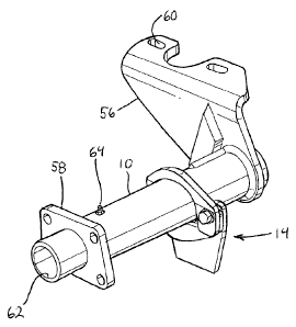
including two members that surround a muffler tube and are clamped together.
The muffler support apparatus surrounds the tube and bolts vertically.
[0008] U.S. Patent 6,240,806 to Morris et al. shows a non-welded cam tube
support assembly. The tube includes a support plate that resists torsional
loading and provides for either inboard or outboard mountings. An inner hole
of
the plate is irregularly shaped to tightly engage the cam tube.
[0009] U.S. Patent 7,537,224 to Morris et al. shows a cam shaft support
enclosure that has a two-piece, non-welded assembly. Two brackets mate with
each other by sliding over a cam tube such that movement of the cam tube is
minimized. Contact with the cam tube is maintained by tabs around an opening
of the assembly. The overall fastener is movable along the length of the cam
tube.
2
CA 02759561 2011-11-28
[0010] U.S. Patent Application Publication 2006/0021834 to Kwasniewski shows
a cam washer that cooperates with a cam tube seal lug to reduce vibration,
prevent corrosion, and hold a seal in place.
SUMMARY OF THE INVENTION
[0011] Introduction of wide-based tires has resulted in increased vibration
and
subsequent damage to drum brake cam tube assemblies. The present invention
is intended to support drum brake cam tubes in such a way as to reduce
vibration that can result in this sort of damage to the cam tube assemblies,
and
provides an improvement over an existing part that was first designed over 30
years ago. A support according to this invention can be attached to a welded
or
bolted frame member, may be used either in production or as a retrofit in the
field, and can be installed independent of the cam tube assembly process. The
present cam tube support serves to withstand the cantilevered load of an air
chamber tube assembly while accommodating a variety of tube diameters via
support jaw camming. Separate tube support pieces that do not rely on splines
for changing the orientation around the cam tube are used, and form a three-
piece assembly that move together to improve holding of cam tubes having
different diameters at different locations along those cam tubes.
[0012] According to one embodiment of the invention, a support arrangement
operable to clamp a tube for a brake assembly in position relative to an
adjacent
vehicle component includes a first jaw having a first pair of arms, each of
which
3
CA 02759561 2011-11-28
,
,
has an one opening in an inclined end section, a second jaw having a second
pair
of arms, each of which has an opening in an inclined end section, and a base
associated with the vehicle component and having a third pair of arms. Each of
the third pair of arms also has an opening in its end section. Bolts or other
such
fastener elements are receivable within aligned sets of openings in the first,
second, and third pairs of arms, permitting displacement of the first and
second
jaws relative to the base upon adjustment of the fasteners so that the jaws
grip
the tube and clamp the tube in its proper position. A clamping process is also
described.
[0013] In certain embodiments of the invention, the jaws have respective solid
central recurved portions interconnecting the arms of the jaws and forming
part-
elliptical or part-circular recesses between the jaw arms. The inclined end
sections of the jaws are bent relative to these central portions to provide
the jaws
with a camming action as the fasteners are tightened. The openings in the jaws
and the base are preferably configured as oblong slots, and, when the
arrangement is assembled, the oblong jaw slots have longer dimensions
extending in directions that are not the same as directions in which longer
dimensions of the oblong base slots extend.
4
CA 02759561 2011-11-28
BRIEF DESCRIPTION OF THE DRAWINGS
[0014] Figure 1 is a side view of a cam tube support fully clamping a
partially
illustrated cam tube in position relative to an associated vehicle component.
[0015] Figure 2 is a front exploded view of certain components of the support
shown in Figure 1.
[0016] Figure 3 is a side view of the components shown in Figure 2.
[0017] Figure 4 is a more comprehensive, perspective view of the cam tube and
certain associated parts.
[0018] Figure 5 is a side view of the structure shown in Figure 4.
[00191 Figure 6 is a perspective view similar to Figure 4, but showing certain
components of the cam tube support in alternative positions.
[00201 Figure 7 is an enlarged plan view of the base of a cam tube support
according to the invention.
[0021] Figure 8 is an enlarged plan view of a jaw of the cam tube support
according to the invention.
DETAILED DESCRIPTION OF THE INVENTION
[0022] The side view provided by Figure 1 shows a partially illustrated cam
tube
as fully clamped in position relative to an axle tube or other such unsprung
vehicle component 12, such as a suspension arm or other linkage, by a clamping
cam tube support 14. In one preferred configuration of the invention, when the
cam tube 10 is mounted in position in a car, truck, or other such vehicle, a
rotatable cam shaft (not shown) extends through the cam tube 10 to
interconnect
a fluid brake actuator and slack adjuster arrangement with a drum brake cam,
which is operable to expand drum brake shoes apart in a known manner. Such
cam shafts are disclosed, for example, in the Hanley et al. ('531), Morris et
al.
('806), and Morris et al. ('224) patents mentioned above as well as the
Kwasniewski ('834) publication mentioned above.
[00231 The clamping cam tube support 14 is composed of three primary parts,
including a base 16 secured by welds 18 or in any other suitable manner to the
unsprung vehicle component 12, an approximately U-shaped lower jaw 20, and
an approximately U-shaped upper jaw 22. As illustrated in the exploded plan
view of Figure 2, the base 16 has an approximately Y-shaped configuration, but
the base 16 could take other forms, and could be U-shaped as well. When the
6
CA 2759561 2018-07-19
CA 02759561 2011-11-28
_
clamping cam tube support 14 is in use, a pair of threaded bolts 24 may pass
through aligned slots in the legs of the base 16 and the jaws 20 and 22.
Cooperating nuts 26 may be tightened onto the ends of the bolts 24 to secure
the
base 16 and jaws 20 and 22 together, thereby fastening the cam tube 10 to the
vehicle component 12.
[0024] Figure 2 provides an illustration of the base 16 and the jaws 20 and 22
in
an exploded plan view. The base 16 is shown as having a central section 29
with
a mounting surface 30, adapted to be secured on a corresponding surface of the
component 12 by the welds 18. The base 16, of course, could be attached to the
component 12 in another suitable way or integrally formed with that component.
The base 16 also has a pair of upstanding extensions defining arms 32. Each
arm is provided with an oblong slot opening 34, with the longer dimension of
the
opening oriented roughly vertically. The term "vertically" is used here and
elsewhere in this specification in a non-limiting manner, and, here, refers to
a
direction in which the arms 32 extend away from the central section 29. A
recess
36 defined between the arms 32 of the base has a circumferential wall 38 with
a
contour matching the contour of the outer surface of the cam tube 10.
[0025] The lower jaw 20 is shown in Figure 2 as having a solid central
recurved
portion 40 and a pair of arms 42. Each arm 42, near its end 43 distal the
central
portion 40, has an oblong slot opening 44, with the longer dimension of the
opening oriented roughly horizontally. The term "horizontally" is used here
and
elsewhere in this specification in a non-limiting manner, and, here, refers to
a
7
CA 02759561 2011-11-28
direction approximately perpendicular to the direction in which the arms 42
extend away from the central portion 40.
[0026] The upper jaw 22 has a configuration that is similar to that of the
lower
jaw 20, and has a solid central recurved portion 46 and a pair of arms 48.
Each
arm 48, near its end 49 distal the central portion 46, has an oblong slot
opening
50, with the longer dimension of the opening oriented roughly horizontally,
similarly to slot openings 44. When the clamping cam tube support 14 is in
use,
the jaws 20 and 22 are oriented such that each arm end 43 is adjacent a
corresponding arm end 49, and the central portions 40 and 46 are located away
from each other. A recess 52 defined between the lower jaw arms 42 is
surrounded by a circumferential wall with a contour matching the contour of
the
outer surface of the cam tube 10, while a recess 54 defined between the upper
jaw arms 48, similarly, is surrounded by a circumferential wall with a contour
matching the contour of the cam tube outer surface.
[0027] The base 16 and the jaws 20 and 22 are shown in Figure 3 in an exploded
side view. It is apparent from Figure 3 that each lower jaw arm 42 has an
inclined or canted section 45 adjacent its end 43, and that each of the
openings
44 is disposed in one of the inclined or canted sections. Each upper jaw arm
48,
similarly, has an inclined or canted section 47 adjacent its end 49, with each
of
the openings 50 disposed in one of the inclined or canted sections 47. The
sections 45 and 47, as shown, are inclined at approximately 15-20 degrees
relative to the remainder of the respective jaw arm, but the amount of
inclination
8
CA 02759561 2011-11-28
shown is not to be considered limiting in any way. Although "camming" would be
produced at any inclination angle in the 1-89 degree range, the range of
preferred inclination angles is important due to load. Increasing the sizes of
the
openings 34, 44, and 50 would allow a wider range of angles.
[0028] The amount of inclination provided to sections 47 can be varied as
required to provide more, or less, clamping force to the barrel of the cam
tube 10.
In conjunction, as the angle of inclination increases, so must the size of the
openings 44 and 50 be varied to accommodate insertion of the bolts 24 when the
jaws are in a vertical position while remaining small enough to prevent the
head
of the bolt 24 and the nut 26 from passing through the openings when
tightened.
The clearance of the jaws 20 and 22 relative to the tube 10 will determine the
travel of the jaws to the clamping position and, in combination with the angle
of
inclination, will determine the amount of clamp force that is developed.
[0029] When different cam brackets are installed, they will always be in
slightly
different locations because of common variations in the manufacturing process.
The two-direction slots allow the clamping tube support to function even with
this variation in tube locations. The horizontal slots in jaws 20 and 22
accommodate variation in the horizontal direction, while the vertical slots in
the
base 16 accommodate variation in the vertical direction. When assembly of the
three parts comes together with bolts, the sets of slots allow the support to
always "center-up" on the cam tube and achieve a good clamp. The support can
also be disassembled and re-used as many times as necessary, avoiding the need
9
CA 02759561 2011-11-28
to cut known support arrangements off the axle and the associated need for re-
welding when a new cam bracket is installed.
[0030] Figure 4 is a more comprehensive view of the cam tube 10 and certain
parts associated therewith. Figure 4 shows the tube 10 in a clamped condition,
after the support 14 has been securely clamped onto the outer surface of the
cam
tube in a manner to be described. It is to be understood that the base 16 must
be
welded to the relevant vehicle component 12 (not shown in Figure 4) before
clamping can take place. The cam tube 10 shown in Figure 4 extends from a
bracket 56, securable to an axle housing or other unsprung vehicle structure
by
bolts receivable in holes 60, to an attachment flange 58, securable to a drum
brake spider, backing plate, or other such element. The rotatable cam shaft
(not
shown) protrudes in a conventional manner through the cam tube end opening
62 and positions the drum brake cam thereon between drum brake shoe ends for
brake actuation. Figure 4 also illustrates a fitting 64 by which grease or
another
lubricant may be supplied to the interior of the cam tube 10 to lubricate cam
shaft bushings provided for the cam tube.
[0031] The clamping tube support 14 may be used in several ways to secure the
tube 10 in position relative to the component 12. One such way is now
described
with reference to Figures 1-3, and 5. The pair of slot openings 44 in the
lower
jaw arms 42 and the pair of slot openings 50 in the upper jaw arms 48 are
aligned, and the shafts of a pair of bolts 24 are passed through the aligned
slot
openings 44 and 50 in a direction indicated by an arrow 55 in Figure 3. Ends
of
CA 02759561 2011-11-28
the bolt shafts are then passed through the slot openings 34 provided in the
arms
32 of the base 16, and the nuts 26 are threaded onto the ends of the bolt
shafts
and tightened to secure the base 16 and jaws 20 and 22 together. As the nuts
are tightened, the head of each bolt 24 and a respective one of the nuts 26
are
displaced toward one another. Due to the presence of the inclined jaw arm
sections 45 and 47, as the nuts 26 are tightened, the lower jaw 20 tends to
pivot
clockwise in the direction indicated by an arrow 66 in Figures 1 and 5, and
the
upper jaw 22 tends to pivot counterclockwise in the direction indicated by an
arrow 68. As the jaws 20 and 22 move in this way, edges of the circumferential
walls surrounding the jaw recesses 52 and 54 frictionally engage or actually
dig
into the outer barrel surface of the cam tube 10, thereby securing the tube 10
in
position relative to the component 12. The camming or lever action provided as
the nuts 26 are tightened allows the jaws to self-center and tightly clamp
onto
the cam tube so that vibration, which could damage the cam tube assembly, is
reduced. Although the two jaw parts try to separate, the slot openings are
designed in such a way that jaw separation is limited, and the jaws bite down
on
the cam tube barrel as the parts get tighter. The present invention permits
relative movement between the jaws and the cam tube along the length of the
cam tube before clamping, and is constructed such that adequate contact is
maintained with the cam tube by the camming action produced by the support
base and jaw configurations after clamping occurs and the relative movement
mentioned is prevented.
11
CA 02759561 2011-11-28
,
[0032] A comparison of Figures 5 and 6 illustrates that the jaws 20 and 22 are
securable to either side of the base 16. The jaws 20 and 22 thus may be
oriented
so as to face in either cam tube axial direction, making attachment of the cam
tube 10 to the component 12 exceptionally easy.
[00331 Figure 7 is an enlarged plan view of the base 16 illustrating the
arrangement of the oblong slot openings 34 in the base arms 32, while Figure 8
is
an enlarged plan view of either the lower jaw 20 or the upper jaw 22,
illustrating
the arrangement of the oblong slot openings 44 or 50 in the arms 42 or 48,
respectively. It is evident that, to produce the jaws 20 and 22 most
efficiently,
they should have essentially the same configuration. By orienting the oblong
slot openings 34 in the arms of the base 16 "vertically" and the slot openings
44
and 50 in the arms of the jaws 20 and 22 "horizontally," appropriate
positional
adjustment of the jaws 20 and 22 with respect to both the cam tube 10 and the
base 16 is facilitated. Orienting the slot openings 44 and 50 horizontally, as
illustrated, serves to limit relative movement of the jaws to ensure tight and
secure engagement of the of the circumferential walls surrounding the recesses
52 and 54 and the outer surface of the cam tube 10.
[0034] It is conceivable to configure the invention such that it has a single
piece
jaw instead of two jaws. The U-shaped upper jaw 22, for example, could alone
be
used to secure the tube 10 to the base 16 and provide clamping.
12
CA 02759561 2011-11-28
=
[0035] Although the use of steel as a jaw material is contemplated, the jaws
20
and 22 could be made of any of a variety of materials. The slot openings 34,
44,
and 50, and the recesses 36, 52, and 54, could be formed by way of any of a
variety of processes, such as stamping or cutting by water jet or laser, or a
combination of such processes. Selection of the bend angle to get the best
clamping action may be necessary, depending on the particular environment in
which the invention is utilized. The "arch" that actually contacts the barrel
could
be an elliptical shape that contacts the barrel in the flatter section, or a
simple
part-circular shape that contacts the barrel mostly at the top when in
position.
Recesses shaped to accommodate other barrel shapes, such as barrels having
square cross sections, are also contemplated.
[0036] By way of the present invention, a cam tube support, adjustable to
accommodate various tube diameters, is provided. The slot configuration of the
three-piece device allows jaw position adjustment both horizontally and
vertically, permitting accommodation of variations in tube diameter and
providing for various tube support locations. Pieces of the device are
structured
so that the support can face either axial direction of the tube, providing
additional mounting configurations. As the three support pieces are fastened
together in a simple manner with two bolts, no welding is necessary, and
manufacturing can be simplified. The base 16 can be pre-welded and attached to
the vehicle component 12 without the need to precisely locate the base 16 on
the
component 12. By having the cam tube support pieces wedge or cam together
when the mounting bolts are tightened, secure contact with the cam tube is
13
CA 02759561 2011-11-28
provided, and vibrations are reduced. The present invention thus provides
varied mountings utilizing a simple design, with three main pieces holding the
relevant vehicle component and the cam tube in proper relative position. The
invention allows for multi-axis variations in location, and consistent contact
is
maintained when a cam tube is installed.
[0037] The cam tube support adjusts to location and tube diameter in such a
way that it always provides adequate contact between the support and the cam
tube. Clamping is accomplished by having one or two clamping members provide
adequate clearance for easy installation. As a final adjustment, the clamping
members self-center and tightly clamp onto the cam tube because of the cam or
lever action caused by the shapes of the clamping members. The invention can
be installed on new equipment or retrofit in the field, is attachable to a
welded or
bolted support leg, and accommodates significant variation in tube diameter
and
location.
[0038] The foregoing disclosure has been set forth merely to illustrate the
invention and is not intended to be limiting. Since modifications of the
disclosed
embodiments incorporating the spirit and substance of the invention may occur
to persons skilled in the art, the invention should be construed to include
everything within the scope of the appended claims and equivalents thereof.
14