Note: Descriptions are shown in the official language in which they were submitted.
CA 02759965 2011-11-29
1
"METHOD AND APPARATUS FOR CONTINUOUS PRODUCTION OF A TEXTILE
STRUCTURE RESISTANT TO PERFORATION AND PENETRATION AND
TEXTILE STRUCTURE THUS OBTAINED"
The present invention refers to a method and an apparatus
for continuous production of a textile structure resistant
to perforation and penetration and to a textile structure
resistant to perforation and penetration thus obtained.
By textile structure resistant to perforation and penetration
it is meant to indicate a multi-layer structure at least
partially made with so-called "ballistic fibers", i.e. with
fibers having high strength, tenacity and elastic modulus,
like, purely as an example, fibers of polyaramid, polyvinyl
alcohol, polyacrylonitrile, polybenzoxazole (PB0), polyolef in,
polyamide, glass or carbon.
Such textile structures generally have characteristics of
flexibility and are used for example to manufacture
bullet-proof, fragments-proof or knife-proof personal armor.
Moreover, if they are suitably treated, for example by
impregnation with a thermoplastic or thermosetting matrix or
by coupling with external coating layers, they can take on
characteristics of rigidity. In this case, they are used to
make helmets, armor or any other rigid item that must offer
resistance to perforation and penetration of bullets,
fragments, pointed or sharp objects and the like.
Currently there are different types of structures that are
resistant to perforation and penetration and different
processes for producing them.
In particular, the known types are at least the following:
CA 02759965 2011-11-29
2
- Structures comprising at least two overlapped layers,
each of which, in turn, comprises a bundle of unidirectional
ballistic fibers that are parallel to one another. The
ballistic fibers of one of such two layers are differently
oriented to the ballistic fibers of the other layer;
generally, the ballistic fibers of one layer are oriented
by an angle comprised between 00 and 90 with respect to
the ballistic fibers of the layer overlapping it. The two
overlapped layers of ballistic fibers are joined together
in various ways. For example this can be by stitching, by
interposition between them of a binding layer or by
impregnation of the ballistic fibers constituting the two
layers with a binding material and subsequent possible
application of pressure and/or heat treatment. Structures
falling into such a type are described for example in
EP 0 683 374 and US 7,148,162, both to Andrew D. Park, and
in EP 0 805 332 and US 2004/0045428, both to Citterio.
- Structures as described for example in EP 1 241 432, to
Teijin Twaron GmbH.
- Structures comprising a fabric made of ballistic fibers
and having at least one surface that has at least one
portion coated with an elastomer on which a plastic film
is applied. Structures of this type are described for
example in US 6,846,758 B2 to A. Bhatnagar (Honeywell
International Inc.).
In greater detail and with particular reference to
structures comprising at least two layers of unidirectional
or semi-unidirectional ballistic fibers, overlapping one
another, the following is noted.
CA 02759965 2011-11-29
3
EP 0 683 374 B1 (Andrew D. Park) describes a panel having a
structure that comprises a first layer, consisting of a
bundle of unidirectional ballistic fibers parallel to one
another, and a second layer, also consisting of a bundle of
unidirectional ballistic fibers parallel to one another and
overlapping the first so that the ballistic fibers of the
second layer are arranged at 900 with respect to the
ballistic fibers of the first layer. Each of the first and
second layer in turn consists of a laminate, which is
produced from a bundle of unidirectional ballistic fibers
that are fed by a creeled yarn package or by a warp beam.
Such ballistic fibers, passing through a thread guide, are
deposited parallel to one another on a plane. The layer of
ballistic fibers thus obtained passes over a roller that
applies a film of thermoplastic material (polyethylene) to
one of the two faces thereof. The assembly thus obtained
passes through a pre-lamination group and the laminate thus
produced is wound around a take-up beam. In order to produce
the panel, two laminates are unwound from the relative
take-up beam and are overlapped one another so that the
ballistic fibers of one are oriented at 900 with respect to
the ballistic fibers of the other and their face coated
with the film of thermoplastic material (polyethylene)
faces outwards. The two laminated layers thus overlapped
are then subjected to heat action so as to melt the film of
polyethylene that covers and encapsulates the ballistic
fibers.
US 7,148,162 B2 describes a laminated panel having a structure
comprising two composite layers that overlap one another.
CA 02759965 2011-11-29
4
Every composite layer comprises a bundle of continuous
ballistic fibers arranged parallel to one another on a
plane and associated with at least one pre-stabilizing net.
The pre-stabilizing net consists of a heat-activated
adhesive polymer. The two composite layers are overlapped
one another so that the ballistic fibers of a composite
layer are oriented at 900 with respect to the ballistic
fibers of the other composite layer. The outer faces of the
two composite layers overlapping one another are coated
with a film of thermoplastic material. The assembly thus
obtained is laminated with application of pressure and heat
to obtain the laminated panel.
The panels described in EP 0 683 374 El and in US 7,148,162 B2
are obtained with discontinuous processes that initially
provide the production of the single composite layers or
laminates separate from one another and, thereafter, the
assembly by overlapping of the single composite layers or
laminates, without interposition between them of intermediate
layers, and the consolidation of the assembly thus obtained
in a multi-layer structure. Such discontinuous processes
require that a plurality of separate operations be carried
out with consequent long execution times that substantially
affect the production costs.
In order to avoid such drawbacks a continuous production
method as described in EP 0 805 332 A2 and in US 2004/0045428
has been proposed. Such a continuous method is carried out
with "textile machines" of the so-called "multi-axial" type,
produced and marketed for example by Liba Maschinenbau
GmbH, which allow different flat layers of unidirectional
CA 02759965 2011-11-29
5
ballistic fibers to be deposited in succession one after
the other and one on top of the other to form a continuous
band. Each flat layer consists of a bundle of ballistic
fibers parallel to one another and the ballistic fibers of
one layer are oriented according to an angle comprised
between 00 and 90 with respect to the ballistic fibers of
the layer beneath it. During the formation of the band, a
film of thermoplastic or thermosetting material is inserted
between the two overlapped layers of ballistic fibers.
The layers of ballistic fibers thus overlapped with the
interposition of film made of thermoplastic or thermosetting
material are then joined through knit stitching. Such knit
stitching is carried out with needles that pass through the
thickness of the various overlapped layers binding them
with a binding thread. The band thus obtained then passes
through a lamination group and is wound in a roll.
Such a method also has a series of drawbacks.
A first drawback consists of the fact that, whilst it is a
continuous method, it requires large available spaces and
in any case involves substantial production times. Indeed,
the formation of every single layer of unidirectional fibers
takes place through a respective thread-comb head, for
which reason in order to make a multi-layer structure it is
necessary to provide different thread-comb heads, one
after another along the line of forward movement of the
band being formed. Each layer of fibers starting from the
second is then deposited on the underlying layer previously
formed by a respective thread-comb head.
Another drawback consists of the fact that the fibers of each
CA 02759965 2011-11-29
6
layer that are deposited by a respective thread-comb head
can deviate from the unidirectionality required, compromising
the properties of resistance to penetration and to perforation
of the panel thus obtained.
A further drawback consists of the fact that if the
ballistic fibers of two successive layers had a relative
orientation of 00/900, the subsequent knit stitching
thereof would not make it possible to obtain a panel with
symmetrical structure, which is however necessary for
ballistic purposes. In order to obtain such a structure it
is forced and limited to deposit the ballistic fibers of two
successive layers with a relative orientation of +45 .
Yet another drawback consists of the fact that the knit
stitching of the various overlapped layers limits the choice
of film to be interposed between two successive layers of
ballistic fibers; such a film, indeed, since it has to be
passed through by needles, cannot have high tenacity.
Moreover, the penetrating needles can damage the ballistic
fibers themselves.
The last but not least drawback of such a known method
consists of the fact that the frames of "multi-axial"
machines with which it is carried out have a fixed width
that cannot be modified. This obviously constitutes a great
limitation to application if one considers the fact that
the market often requires panels of different widths.
EP 1 241 432 B1, on the other hand, describes a multi-layer
structure consisting of two weft and warp woven fabric
pieces and wherein the warp threads of one of the two
fabric pieces and the weft threads of the other of the two
CA 02759965 2011-11-29
7
fabric pieces consist of ballistic fibers. The other threads,
weft and warp respectively, of the two fabric pieces consist
of binding threads. The two fabric pieces are overlapped
and joined together for example by stitching, by lamination
or by impregnation with resins.
This last method is also discontinuous and foresees the
weaving of each of the two fabric pieces on a respective
traditional loom for the weft and warp weaving. Each of the
two woven fabric pieces is then wound up in a roll. The two
fabric pieces are then overlapped and laminated together with
the interposition between them of an adhesive film or glue.
The assembly thus obtained is then subjected to subsequent
finishing treatments.
The weaving of each of the two fabric pieces with a
respective traditional loom for the weft and warp weaving
requires long execution times and equally high investment
and management costs.
These drawbacks in terms of productivity and costs are
worsened even further by the subsequent assembly and
coupling operations of the woven fabric pieces that are
carried out successively and in separate stations.
Another drawback consists of the fact that the single woven
fabric pieces have low stability due to the presence of the
binding threads woven with the ballistic fibers. The binding
threads, indeed, have the purpose of allowing the weaving
of the ballistic fibers, and for this reason they are
generally thin and have low tenacity thus making the fabric
structurally not very stable. This makes it difficult to
manipulate the single fabric pieces and to overlap them
CA 02759965 2011-11-29
8
exactly so as to keep the ballistic fibers correctly
oriented.
There are also known textile structures comprising two
overlapped layers each of which consists of a bundle of
unidirectional and coplanar ballistic fibers, wherein the
fibers of one layer are oriented at 90 with respect to the
fibers of the other layer and the fibers of the two layers
are stabilized by a plain-woven of binding threads interwoven
in weft and warp between them. Examples of multi-layer
structures of this type are described in WO 02/090866 or in
WO 05/028724.
The purpose of the present invention is to propose a method
for continuous production of a textile structure resistant
to perforation and penetration that allows a multilayer
textile structure to be obtained in a short time and with
low investment and management costs and, therefore, with
greater productivity with respect to known processes.
Another purpose of the present finding is to provide a
method for continuous production of a textile structure
resistant to perforation and penetration that allows a
multilayer textile structure to be obtained that is
structurally stable, i.e. in which the ballistic fibers
maintain the desired orientation without undergoing
deviations or overlapping with respect to one another and
without them being damaged.
Yet another purpose of the present finding is to provide a
continuous method that allows to obtain textile structures
resistant to penetration and perforation the width of which
can easily be modified.
CA 02759965 2011-11-29
9
Another purpose of the present invention is to propose an
apparatus for implementing a method for continuous production
of a textile structure resistant to perforation that is
particularly simple and functional and has reduced overall
dimensions.
These purposes according to the present invention are
accomplished with a method for continuous production of a
textile structure resistant to perforation and penetration
as outlined in claim 1.
These purposes are also accomplished with an apparatus for
implementing the method for continuous production of a
textile structure resistant to perforation and penetration
as outlined in claim 7.
These purposes are also accomplished with a textile structure
resistant to perforation and penetration as outlined in
claim 12.
Further characteristics are foreseen in the dependent
claims.
The characteristics of the present invention will become
clearer from the following description, given as an example
and not for limiting purposes, referring to the attached
drawings in which:
figure 1 is a side elevational schematic view of an apparatus
for implementing the method for producing a textile structure
resistant to perforation and penetration according to the
present invention;
figure 2 is a side elevational schematic view of an alternative
embodiment of the apparatus for implementing the method for
producing a textile structure resistant to perforation and
CA 02759965 2011-11-29
10
penetration according to the present invention;
figures 3a, 3b, 4a and 4b schematically show section views
of possible textile structures obtained with the method
according to the present invention.
In the following description by the expression "textile
structure resistant to perforation and penetration" it is
meant to indicate a multilayer textile structure made at
least partially with so-called "ballistic fibers", i.e. fibers
with high resistance, tenacity and elastic modulus.
In particular, the present invention refers to a method and
an apparatus for continuous production of a textile structure
resistant to perforation and penetration of the multi-layer
type and comprising at least two fabric elements overlapping
one another, each of which is made, at least in part, with
"ballistic fibers" having "unidirectional" extension.
In the following description, moreover, the adjectives "upper"
and "lower" are used to indicate the relative arrangement
between elements arranged at different heights with respect
to a reference plane.
The method for continuous production of a textile structure
resistant to perforation and penetration, according to the
present invention, comprises the steps consisting in:
a) simultaneously weaving two fabric elements overlapped
and spaced from each other, respectively an upper fabric
element ES and a lower fabric element El, wherein each of
the two upper ES and lower El fabric elements comprises a
bundle of warp threads 1 which are at least partially made
of ballistic threads and which are arranged parallel to
each other on a first plane, a bundle of weft threads 2
CA 02759965 2011-11-29
11
which are at least partially made of ballistic threads and
which are arranged parallel to each other on a second plane
overlapped to the first and oriented at 900 +5 with respect
_
to the warp threads 1 and a stabilization weave 3 interwoven
between the warp 1 and weft 2 threads of the two overlapped
planes and made of first binding threads 30 and 31;
b) joining, during step a) of simultaneously weaving the two
fabric elements ES and El overlapped and spaced from each
other, the upper fabric element ES and the lower fabric
element El to form a multilayer textile structure SM with
second binding threads 4 alternatingly interwoven therein.
Step b) of joining the upper fabric element ES with the
lower fabric element El consists of providing a warp or
chain of second binding threads 4 and of weaving the latter
alternatingly and according to different schemes in the upper
fabric element ES and in the lower fabric element El.
The stabilization weave 3 of each of the two upper ES and
lower El fabric elements in turn comprises:
- a weft of first binding threads 30, which are arranged
parallel to one another in a bundle on a plane beneath the
warp threads 1 and not interwoven with them;
- a warp of first binding threads 31, which are alternatingly
woven with the weft threads 2 (ballistic) and with the weft
of the first binding threads 30.
The method according to the finding also comprises the
steps consisting in:
c) inserting, during the weaving step a), at least one
intermediate layer SI in the form of strips or threads
parallel to the warp direction between the two upper ES and
CA 02759965 2011-11-29
12
lower El fabric elements;
d) joining the assembly of the two upper ES and lower El
fabric elements joined together by the second binding
threads 4 and between which the intermediate layer SI is
interposed to obtain a multilayer textile structure SM'.
The joining step d) occurs by hot or cold pressing the
assembly of the two fabric elements ES and El joined
together by the second binding threads 4 and interposed
between which is the intermediate layer SI.
The joining step d) is carried out in line with the weaving
step of the two upper ES and lower El fabric elements and
the insertion between them of the intermediate layer SI.
The method according to the finding finally comprises a
final step of collecting the multilayer structure SM, SM'
whether it consists of the two upper ES and lower El fabric
elements joined together by the second binding threads 4 or
it consists of the two upper ES and lower El fabric elements
joined together by the second binding threads 4 between
which also the intermediate layer SI is interposed.
After the possible joining step d) and before the collection
step, there can be at least one hot or cold calandering
step of the multilayer textile structure SM.
Again after the joining step and before the collecting
step, it is possible to provide a step of applying, for
example by impregnation or lamination, to at least one of
the two opposite faces of the multilayer textile structure,
at least one impregnating substance or at least one surface
coating, respectively.
Preliminarily to the step of applying such an impregnating
CA 02759965 2011-11-29
13
substance or surface coating, it is possible to carry out
one or more washing steps of the multilayer textile structure
and/or one or more corona and/or plasma treatment steps.
The steps indicated above, in particular those of washing,
corona and/or plasma treatment, application of at least one
surface coating layer and calandering are not described in
detail since they can easily be recognized and worked out
by the man skilled in the art.
As an alternative to carrying out the washing, corona
and/or plasma treatment steps and subsequent impregnation
of the multilayer textile structure, it is possible to use
for the weaving of the two upper and lower fabric elements,
threads that have already been pre-treated and impregnated
in particular with water-repellent substances, including
preferably fluoropolymers.
By ballistic threads, as known to the man skilled in the art,
it is meant to indicate threads made of ballistic fibers.
In particular, the ballistic fibers are made of a polymeric
material selected from the group comprising at least:
poly-para-aramid, polycopoly-aramid, polybenzoxazole,
polybenzothiazole, polyketone, polyethylene, polypropylene,
polyesters with aromatic base, glass, carbon and basalt and
the like. Indeed, other types of ballistic fibers are not
ruled out.
In a preferred embodiment of the method object of the
invention, the ballistic threads have the following
characteristics:
- tensile strength > 7 gr/dtex
- elastic modulus > 200 gr/dtex
CA 02759965 2011-11-29
14
- impact strength > 10 J/gr
- density > 0,8 gr/cmc
- count comprised between 100 dtex and 10000 dtex.
On the other hand, with regard to the first and second
binding threads, they are made of thermoplastic polymeric
material, thermosetting polymeric material, soluble material
or their blends.
It should be specified that, in a possible embodiment of
the method object of the present invention, the same first
and second binding threads can have ballistic properties.
If present, the intermediate layer SI is made of thermoplastic
polymeric material, thermosetting polymeric material,
elastomeric material, viscous material, adhesive polymers
and their blends.
As a non-exhaustive example, the intermediate layer SI is
made of a polymer selected from the group comprising at
least: polyurethane, polyethylene, polypropylene, polyester,
styrene butadiene, polycarbonate, phenol or polyvinyl butyral,
polyisobutene, polyisobutylene, natural or synthetic rubber,
silicon polymers and the like.
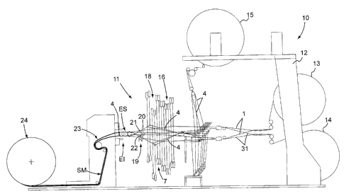
Figure 1 represents the scheme of an apparatus 10 for
implementing the method according to the finding.
The apparatus 10 comprises a weaving loom 11 with two
overlapped fabric pieces of the warp pile fabric velvet
loom type. In its base structure the loom 11 comprises:
- a support framework 12,
- at least one feeding group consisting of a first beam 13
from which the warp of ballistic threads 1 is unwound
respectively of the upper fabric element ES and of the
CA 02759965 2011-11-29
15
lower fabric element El,
- at least one first feeding group consisting of a second
beam 14 from which the warp of the first binding threads 31
of the stabilization weave 3 is unwound respectively of the
upper fabric element ES and of the lower fabric element El;
- at least one second feeding group consisting of a third
beam 15 of the warp or chain of the second binding threads
4 of the upper fabric element ES with the lower fabric
element El;
- at least one first order of heddles 16 for the warp,
ballistic 1 and binding 31 threads, of the upper fabric
element ES and a second order of heddles 17 for the warp,
ballistic 1 and binding 31 threads, of the lower fabric
element El,
- at least one third order of heddles 18 for the warp of
the second binding threads 4 of the upper fabric element ES
with the lower fabric element El;
- a sley 19 bearing a reed 20 passing between whose teeth
are the warp, ballistic 1 and binding 31 threads, of the
upper fabric element ES and of the lower fabric element El,
and the warp of the second binding threads 4;
- at least two members 21 and 22 for simultaneously inserting
the weft threads, alternatingly ballistic 2 and binding 30
threads, respectively into the upper and lower warp mouths
defined by the orders of heddles for respectively forming
the upper fabric element ES and the lower fabric element El
joined together by the second binding threads 4;
- a drawing group 23 of the two upper ES and lower El fabric
elements joined together by the second binding threads 4 in
CA 02759965 2011-11-29
16
a multilayer textile structure SM, such a drawing group
being arranged downstream of the loom 11;
- a group 24 for collecting the multilayer textile structure
SM arranged downstream of the drawing group 23.
The insertion members 21 and 22 can consist of respective
pincers, lances, shuttles or an air jet and they work in
cooperation with a so-called "presenter" for the alternating
insertion of the weft of the first binding threads 30 and
of the weft of the ballistic threads 2.
It should be specified that in the attached figures and in
the present description the motorization members, the movement
mechanisms, the guide, separating, control and selection
members that, as known to the man skilled in the art, fit
out and complete the structure of the weaving loom 11, are
not represented and described in detail.
The drawing group 23 comprises at least one pair of pressure
rollers parallel and counter-rotating with respect to one
another, so-called take up beam, which can be heated.
The collecting group 24 comprises a beam for collecting the
multilayer textile structure SM formed.
Figure 2 represents the scheme of an alternative embodiment
of the apparatus 10 that differs from the embodiment
represented in figure 1 in that it comprises a further
feeding group 25 of the intermediate layer SI arranged near
to the first and second beam 13 and 14.
Such a further feeding group 25 can consist of a beam from
which the threads or the strips of the intermediate layer
SI are unwound. Alternatively, it can consist of a roll
from which the intermediate layer SI unwinds in the form of
CA 02759965 2011-11-29
17
continuous film, a group for cutting the continuous film
into a plurality of threads or strips parallel to the warp
direction being provided downstream of such a roll.
The cutting group can, for example, consist of a plurality
of circular blades mounted on a shaft transversal to the
warp direction and cooperating with corresponding
counter-blades.
In such an embodiment the drawing group 23 also carries out
the joining of the upper fabric element ES and of the lower
fabric element El, joined together by the second binding
threads 4, between which the intermediate layer SI is
interposed.
Figure 2 also schematically represents further groups that
complete the apparatus 10, in particular:
- A hot or cold calandering group 26 interposed between
the drawing group 23 and the collecting group 24.
- A washing group 27 of the multilayer textile structure
SM, a corona or plasma treatment group 28 of the multilayer
textile structure SM and a group 29 for applying, by
impregnation or by lamination, at least one impregnated
substance or a surface coating onto at least one of the two
faces of the multilayer textile structure SM. It should be
understood that also just some of the groups indicated
above may be provided, for example just the calandering group,
or many series thereof even in a different succession. The
same groups are not necessary in the case in which threads
already pre-treated and impregnated with a water-repellent
substance, preferably based on fluoropolymer, are used for
the weaving of the two upper and lower fabric elements.
CA 02759965 2011-11-29
18
The calandering, washing, corona and plasma treatment,
impregnation or surface coating layer application groups
are not described in detail since they are known to the man
skilled in the art.
The operation of the apparatus 10 can be immediately
understood by the man skilled in the art, with particular
reference to the weaving of the warp pile fabric velvet.
Figures 3a, 3b, 4a and 4b show, schematically and not to
scale, possible multilayer textile structures SM obtainable
with the method according to the finding, wherein the
ballistic threads are indicated with a thick line and the
first and second binding threads with a thin line.
The structures according to figures 3b and 4b respectively
differ from those of figures 3a and 4a due to the presence
of the intermediate layer SI between the upper fabric
element ES and the lower one El.
It should also be specified that the path of the second
binding threads 4 represented in the attached figures is
indicative and an example, with it of course being able to
be different, as can be easily understood by the man skilled
in the art.
Thanks to the simultaneous weaving of two fabric elements
overlapped and spaced from each other, and their simultaneous
joining with the second binding threads, alternatingly
interwoven therein, the method and apparatus according to the
present invention make it possible to obtain a multilayer
textile structure in a single stage. This makes it possible
to reduce production times and costs and, therefore, to
increase productivity with respect to known methods.
CA 02759965 2011-11-29
19
The method and apparatus according to the present invention
make it possible to obtain multilayer textile structures
resistant to perforation and penetration in which the
ballistic threads are aligned in the desired direction and
do not suffer damage or relative displacements, with a
consequent improvement of the ballistic properties. A
further stabilization of the ballistic textile structure
and improvement of its properties are obtained thanks to
the insertion of the intermediate layer between the two
fabric elements, said insertion occurring at the same time
as the weaving of the two fabric elements and their
attachment and joining with the second binding threads.
The method and apparatus according to the present invention
make it possible to obtain multilayer textile structures
resistant to perforation and penetration of any width,
being it sufficient to modify the number of warp threads.
The method for producing the textile structure resistant to
perforation and penetration and the apparatus for carrying
it out thus conceived can undergo numerous modifications
and variants, all of which are covered by the invention;
moreover, all of the details can be replaced with technically
equivalent elements. In practice, the materials used, as well
as the sizes, can be whatever according to the technical
requirements.