Note: Descriptions are shown in the official language in which they were submitted.
CA 02760191 2011-10-27
WO 2010/130031 PCT/CA2010/000701
FLUID TREATMENT SYSTEM
CROSS-REFERENCE TO RELATED APPLICATION
[0001] The present application claims the benefit under 35 U.S.C. 119(e) of
provisional patent
application S.N. 61/213,136, filed May 11, 2009, the contents of which are
hereby incorporated
by reference.
BACKGROUND OF THE INVENTION
FIELD OF THE INVENTION
[0002] The present invention relates to a fluid treatment system. More
particularly, the present
invention relates to a fluid treatment system for treatment of liquids such as
water. Even more
particularly, the present invention relates to a fluid treatment system for
treatment of water such
as ballast water from marine vessels.
DESCRIPTION OF THE PRIOR ART
[0003] Fluid treatment systems are generally known in the art. More
particularly, ultraviolet
(UV) radiation fluid treatment systems are generally known in the art. Early
treatment systems
comprised a fully enclosed chamber design containing one or more radiation
(preferably UV)
lamps. Certain problems existed with these earlier designs. These problems
were manifested
particularly when applied to large open flow treatment systems which are
typical of larger scale
municipal waste water or potable water treatment plants. Thus, these types of
reactors had
associated with them the following problems:
= relatively high capital cost of reactor;
= difficult accessibility to submerged reactor and/or wetted equipment
(lamps, sleeve cleaners, etc);
SUBSTITUTE SHEET (RULE 26)
CA 02760191 2011-10-27
WO 2010/130031 PCT/CA2010/000701
= difficulties associated with removal of fouling materials from fluid
treatment equipment;
= relatively low fluid disinfection efficiency, and/or
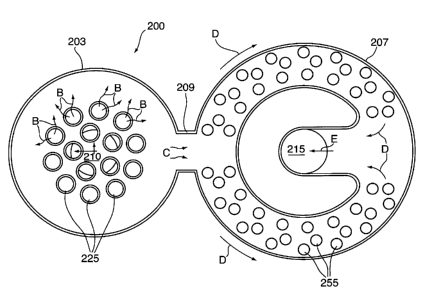
= full redundancy of equipment was required for maintenance of wetted
components (sleeves, lamps and the like).
[0004] The shortcomings in conventional closed reactors led to the development
of the so-called
"open channel" reactors.
[0005] For example, United States patents 4,482,809, 4,872,980 and 5,006,244
(all in the name
of Maarschalkerweerd and all assigned to the assignee of the present invention
and hereinafter
referred to as the Maarschalkerweerd #1 Patents) all describe gravity fed
fluid treatment systems
which employ ultraviolet (UV) radiation.
[0006] Such systems include an array of UV lamp modules (e.g., frames) which
include several
UV lamps each of which are mounted within sleeves which extend between and are
supported by
a pair of legs which are attached to a cross-piece. The so-supported sleeves
(containing the UV
lamps) are immersed into a fluid to be treated which is then irradiated as
required. The amount
of radiation to which the fluid is exposed is determined by the proximity of
the fluid to the
lamps, the output wattage of the lamps and the flow rate of the fluid past the
lamps. Typically,
one or more UV sensors may be employed to monitor the UV output of the lamps
and the fluid
level is typically controlled, to some extent, downstream of the treatment
device by means of
level gates or the like.
[0007] The Maarschalkerweerd #1 Patents teach fluid treatment systems which
were
characterized by improved ability to extract the equipment from a wetted or
submerged state
without the need for full equipment redundancy. These designs
compartmentalized the lamp
arrays into rows and/or columns and were characterized by having the top of
the reactor open to
provide free-surface flow of fluid in a "top open" channel.
2
SUBSTITUTE SHEET (RULE 26)
CA 02760191 2011-10-27
WO 2010/130031 PCT/CA2010/000701
[00081 The fluid treatment system taught in the Maarschalkerweerd #1 Patents
is characterized
by having a free-surface flow of fluid (typically the top fluid surface was
not purposely
controlled or constrained). Thus, the systems would typically follow the
behaviour of open
channel hydraulics. Since the design of the system inherently comprised a free-
surface flow of
fluid, there were constraints on the maximum flow each lamp or lamp array
could handle before
either one or other hydraulically adjoined arrays would be adversely affected
by changes in water
elevation. At higher flows or significant changes in the flow, the
unrestrained or free-surface
flow of fluid would be allowed to change the treatment volume and cross-
sectional shape of the
fluid flow, thereby rendering the reactor relatively ineffective. Provided
that the power to each
lamp in the array was relatively low, the subsequent fluid flow per lamp would
be relatively low.
The concept of a fully open channel fluid treatment system would suffice in
these lower lamp
power and subsequently lower hydraulically loaded treatment systems. The
problem here was
that, with less powerful lamps, a relatively large number of lamps was
required to treat the same
volume of fluid flow. Thus, the inherent cost of the system would be unduly
large and/or not
competitive with the additional features of automatic lamp sleeve cleaning and
large fluid
volume treatment systems.
[0009] This led to the so-called "semi-enclosed" fluid treatment systems.
[0010] United States patents 5,418,370, 5,539,210 and Re36,896 (all in the
name of
Maarschalkerweerd and all assigned to the assignee of the present invention
and hereinafter
referred to as the Maarschalkerweerd #2 Patents) all describe an improved
radiation source
module for use in gravity fed fluid treatment systems which employ UV
radiation. Generally,
the improved radiation source module comprises a radiation source assembly
(typically
comprising a radiation source and a protective (e.g., quartz) sleeve)
sealingly cantilevered from a
support member. The support member may further comprise appropriate means to
secure the
radiation source module in the gravity fed fluid treatment system.
[0011] The Maarschalkerweerd #2 Patents are characterized by having a closed
surface
confining the fluid being treated in the treatment area of the reactor. This
closed treatment
system had open ends which, in effect, were disposed in an open channel. The
submerged or
wetted equipment (UV lamps, cleaners and the like) could be extracted using
pivoted hinges,
3
SUBSTITUTE SHEET (RULE 26)
CA 02760191 2011-10-27
WO 2010/130031 PCT/CA2010/000701
sliders and various other devices allowing removal of equipment from the semi-
enclosed reactor
to the free surfaces.
[0012] The fluid treatment system described in the Maarschalkerweerd #2
Patents was typically
characterized by relatively short length lamps which were cantilevered to a
substantially vertical
support arm (i.e., the lamps were supported at one end only). This allowed for
pivoting or other
extraction of the lamp from the semi-enclosed reactor. These significantly
shorter and more
powerful lamps inherently are characterized by being less efficient in
converting electrical
energy to UV energy. The cost associated with the equipment necessary to
physically access and
support these lamps was significant.
[0013] Historically, the fluid treatment modules and systems described in the
Maarschalkerweerd #1 and #2 Patents have found widespread application in the
field of
municipal waste water treatment (i.e., treatment of water that is discharged
to a river, pond, lake
or other such receiving stream).
[0014] In the field of municipal drinking water, it is known to utilize so-
called "closed" fluid
treatment systems or "pressurized" fluid treatment systems.
[0015] Closed fluid treatment devices are known - see, for example, United
States patent
5,504,335 (Maarschalkerweerd #3). Maarschalkerweerd #3 teaches a closed fluid
treatment
device comprising a housing for receiving a flow of fluid. The housing
comprises a fluid inlet, a
fluid outlet, a fluid treatment zone disposed between the fluid inlet and the
fluid outlet, and at
least one radiation source module disposed in the fluid treatment zone. The
fluid inlet, the fluid
outlet and the fluid treatment zone are in a collinear relationship with
respect to one another. The
at least one radiation source module comprises a radiation source sealably
connected to a leg
which is sealably mounted to the housing. The radiation source is disposed
substantially parallel
to the flow of fluid.
[0016] United States patent 6,500,346 [Taghipour et al. (Taghipour)] also
teaches a closed fluid
treatment device, particularly useful for ultraviolet radiation treatment of
fluids such as water.
The device comprises a housing for receiving a flow of fluid. The housing has
a fluid inlet, a
4
SUBSTITUTE SHEET (RULE 26)
CA 02760191 2011-10-27
WO 2010/130031 PCT/CA2010/000701
fluid outlet, a fluid treatment zone disposed between the fluid inlet and the
fluid outlet and at
least one radiation source having a longitudinal axis disposed in the fluid
treatment zone
substantially transverse to a direction of the flow of fluid through the
housing. The fluid inlet, the
fluid outlet and the fluid treatment zone are arranged substantially
collinearly with respect to one
another. The fluid inlet has a first opening having: (i) a cross-sectional
area less than a cross-
sectional area of the fluid treatment zone, and (ii) a largest diameter
substantially parallel to the
longitudinal axis of the at least one radiation source assembly.
[0017] The various embodiments described in the the Maarshalkerweerd #1
Patents, the
Maarschalkerweerd #2 Patents and the Maarschalkerweerd #3 Patents relate to
land-based fluid
radiation treatment systems. Typically, the fluid radiation treatment systems
are used in
conjunction with other treatment systems in the municipal wastewater treatment
plant or the
municipal drinking water treatment plant, as the case may be. In such
installations, various
conduit systems and the like are used to interconnect the fluid radiation
treatment system to the
other fluid treatment systems in the installation.
[0018] It is conventional in such installations to compartmentalize each
treatment system in the
installation such that each treatment system is configured to create its own
optimized flow fluid.
This approach has been satisfactory for land-based fluid treatment systems.
[0019] A problem arises in applications of fluid treatment systems where a
very small footprint
is available for overall fluid treatment. This problem arises particularly
when it is desired to treat
ballast water in shipping vessels.
[0020] The continuous introduction and spread of aquatic non-indigenous
species is a serious
threat to the marine environment . Unlike other forms of pollution, once a non-
indigenous
species establishes itself, it will remain in its new location. While
calculating the potential side
effects on human food supply, economy, health and overall biodiversity is
difficult, there is
widespread acceptance that the cost could be staggering.
[0021] One primary culprit for introduction and spread of aquatic non-
indigenous species is due
to unabated transferance of ballast water from shipping vessels. Ballast water
taken on in one
SUBSTITUTE SHEET (RULE 26)
CA 02760191 2011-10-27
WO 2010/130031 PCT/CA2010/000701
body of water or ecological zone and released into another body of water or
ecological zone can
introduce so-called Aquatic Invasive Species (AIS) that has the potential to
cause detrimental
impact on one or more of the biodiversity, economy and human health of the
receiving
community.
[0022] Typically, a shipping vessel will take on ballast water (fresh water
and/or salt water) and
at a source point and hold this in onboard ballast tanks and/or cargo holds to
increase stability
and maneuverability during transit. Once the shipping vessel arrives at its
destination point, the
ballast water is typically discharged from the onboard ballast tanks and/or
cargo holds. Also, it
is common for ballast water to be taken on and/or discharged during transit
between the source
point and the destination point. It has been estimated that 3-5 billon tonnes
of ballast water is
transferred in this manner on an annual basis.
[0023] It would be desirable to have an onboard system capable of treating the
ballast water to
reduce the indigenous AIS transferred from the source point to the destination
point (or to points
therebetween). Such a system would need to include the major treatment systems
and need to be
able to occupy only a very small footprint on the shipping vessel.
SUMMARY OF THE INVENTION
[0024] It is an object of the present invention to obviate or mitigate at
least one of the above-
mentioned disadvantages of the prior art.
[0025] It is another object of the present invention to provide a novel fluid
treatment system.
[0026] Accordingly, in one of its aspects, the present invention provides a
fluid treatment system
comprising: (i) a fluid inlet; (ii) a fluid outlet; and (iii) a fluid
treatment zone in fluid
communication with the fluid inlet and the fluid outlet, the fluid treatment
zone comprising a
housing within which is disposed a fluid separation section (the separation
section may include a
single separation device or a combination of two or more similar or disimilar
separation devices)
and a fluid radiation section in fluid communication with one another.
6
SUBSTITUTE SHEET (RULE 26)
CA 02760191 2011-10-27
WO 2010/130031 PCT/CA2010/000701
100271 In another of its aspects, the present invention provides a fluid
treatment system
comprising: a fluid inlet; a fluid outlet; and a closed fluid treatment zone
in fluid communication
with the fluid inlet and the fluid outlet, the fluid treatment zone comprising
a housing, the
housing comprising (a) a first chamber in fluid communication with the fluid
inlet and within
which is disposed at least one fluid separation section (the separation
section may include a
single separation device or a combination of two or more similar or disimilar
separation devices),
and (b) a second chamber in fluid communication with the fluid outlet and the
first chamber, the
second chamber having disposed therein at least one radiation source assembly;
wherein the first chamber and the second chamber are disposed substantially
coaxially
with respect to one another.
[00281 Thus, the present inventor has developed a fluid treatment system
which, in a general
sense, includes a fluid separation section and a fluid radiation section. The
fluid separation
section removes solids in the fluid and the fluid radiation section irradiates
the fluid to deactive
microorganisms and/or contaminants in the fluid. Importantly, the fluid
separation section and
the fluid radiation section are configured to have a substantially common
fluid flow path which
significantly reduces the space or footprint requirement of and/or
significantly reduces hydraulic
head loss (pressure drops) in the overall fluid treatment system while
allowing the two sections
to perform their respective functions.
100291 This can be understood with references to Figures A and B. Figure A
illustrates a
conventional flow wherein a fluid separation section and fluid radiation
section are physically
independent and are interconnected by intermediate pipe 2. The fluid
separation section and
fluid radiation section each must establish their own fluid flow for proper
operation of the
section. This results in significant oscillation of fluid pressure between
inlet pipe I and outlet
pipe 3. In contrast, with reference to Figure B, by combining the fluid
separation section and
fluid radiation section as shown, the oscillation of fluid pressure between
inlet pipe 1 and outlet
pipe 3 is obviated or mitigated. This allows for the two sections to perform
their respective
functions which significantly reduces the space or footprint requirement for
the overall fluid
treatment system.
7
SUBSTITUTE SHEET (RULE 26)
CA 02760191 2011-10-27
WO 2010/130031 PCT/CA2010/000701
[0030] In many cases, the fluid separation section and the fluid radiation
section are contained in
a unitary house or enclosure that is configured to created a "developed fluid
flow" between both
sections. By "developed fluid flow" is meant that the general hydrodynamics of
the flow fluid
are substantially developed in the fluid separation section and do not need to
be fully
redeveloped in the fluid radiation section.
[0031] Preferably, the fluid treatment system is adapted for treament of
liquid, more preferably
water.
[0032] The separation section of the present fluid treatment system serves to
remove solids from
the fluid. Thus, this section can incorporation a wide variety of physical
separation components
- e.g., a filter, a membrane and the like. The physical design of the
separation components is
variable - e.g., they may be cylindrically shaped or they may be non-
cylindrically shape (curved
or planar). The separation section may include a single separation device or a
combination of
two or more similar or disimilar separation devices.
BRIEF DESCRIPTION OF THE DRAWINGS
[0033] Embodiments of the present invention will be described with reference
to the
accompanying drawings, wherein like reference numerals denote like parts, and
in which:
Figure A illustrates a schematic view of a conventional approach to fluid
treament;
Figure B illustrates a schematic view of a fluid treatment approach utilized
by the present
fluid treatment system;
Figures 1-9 illustrate various views of a first embodiment of the present
fluid treatment
system, including various views of components of the fluid treatment system;
Figures 10-17 illustrate various views of a second embodiment of the present
fluid
treatment system, including various views of components of the fluid treatment
system;
Figures 18-21 illustrate various views of a third embodiment of the present
fluid
treatment system; and
8
SUBSTITUTE SHEET (RULE 26)
CA 02760191 2011-10-27
WO 2010/130031 PCT/CA2010/000701
Figure 22 illustrates a view of a modified version of the fluid treatment
system illustrated
in Figures 18-21.
DETAILED DESCRIPTION OF THE PREFERRED EMBODIMENTS
100341 In one of its aspects, the present invention relates to a fluid
treatment system fluid
treatment system comprising: (i) a fluid inlet; (ii) a fluid outlet; and (iii)
a fluid treatment zone in
fluid communication with the fluid inlet and the fluid outlet, the fluid
treatment zone comprising
a housing within which is disposed a fluid separation section and a fluid
radiation section in fluid
communication with one another. Preferred embodiments of this embodiment of
the present
invention may include any one or a combination of any two or more any of the
following
features:
= the fluid separation section may be in fluid communication with the fluid
inlet;
= the fluid radiation section may be in fluid communication with the fluid
outlet;
= the fluid separation section may be in fluid communication with the fluid
inlet, and
the fluid radiation section is in fluid communication with the fluid outlet;
= the fluid treatment zone may be configured to receive a pressurized flow of
fluid;
= the fluid treatment zone may be configured to constrain on all sides a flow
of fluid
received from the fluid inlet;
= the fluid separation section may comprise a filter element (e.g., bag
filtration,
cartridge filtration with a wide variety of filtering materials, ceramic
filtration, screen
filtration, woven wire filtration, cloth filtration, wedgwire filtration,
plastic filtration
granular filtration (sacrificial and non-sacrificial) and any combination of
two or
more of these);
= the fluid separation section may comprise a cyclone element;
= the fluid separation section may comprise a membrane element;
9
SUBSTITUTE SHEET (RULE 26)
CA 02760191 2011-10-27
WO 2010/130031 PCT/CA2010/000701
= the fluid separation section may comprise at least one candle filter;
= the at least one candle filter may comprise an elongate filter housing
having an filter
inlet in fluid communication with the fluid inlet and a filter outlet in fluid
communication with fluid radiation section;
= the filter housing may comprise a substantially cylindrical portion;
= the elongate filter housing may be fluid permeable between the filter inlet
and the
filter outlet to allow for fluid to pass laterally from an interior to an
exterior of the
filter housing or from an exteriod to an interior of the filter housing;
= the filter housing may comprise a filter element on an inner surface of the
filter
housing;
= the filter housing may comprise a filter element on substantially an entire
inner
surface of the filter housing;
= the filter element may comprise a ceramic material;
= the filter element may comprise a porous ceramic material;
= the filter element may comprise a metal tube;
= the filter element may comprise a sintered metal tube;
= the filter element may comprise an expanded sheet material;
= the filter element comprises an expanded metal sheet material;
= the filter element may comprise a mesh screen;
= the filter element may comprise a woven mesh screen;
= the filter element may comprise a filter cloth material;
SUBSTITUTE SHEET (RULE 26)
CA 02760191 2011-10-27
WO 2010/130031 PCT/CA2010/000701
= the filter element may comprise a non-undulating surface;
= the filter element may comprise an undulating surface;
= the fluid separation section may comprise a plurality of separation elements
arranged
in a separation element array;
= each separation element may be configured to receive a flow of fluid;
= each separation element may be configured to receive an independent flow of
fluid
with respect to an adjacent separation element;
= each separation element may be elongate;
= each separation element may comprise a longitudinal axis that is
substantially parallel
with respect to a longitudinal axis of at least two adjacent separation
elements;
= each separation element may comprise a longitudinal axis that is
substantially
equidistant from longitudinal axis of three adjacent separation elements;
= each separation element may comprise a longitudinal axis that is
substantially
equidistant from longitudinal axis of four adjacent separation elements;
= each separation element may comprise a longitudinal axis that is
substantially
equidistant from longitudinal axis of five adjacent separation elements;
= the fluid radiation section may comprise at least one elongate radiation
source
assembly;
= the at least one elongate radiation source assembly may comprise at least
one
elongate radiation source;
= the at least one elongate radiation source may comprise an ultraviolet
radiation
source;
11
SUBSTITUTE SHEET (RULE 26)
CA 02760191 2011-10-27
WO 2010/130031 PCT/CA2010/000701
= the ultraviolet radiation source may comprise a low pressure ultraviolet
radiation
lamp;
= the ultraviolet radiation source may comprise a low pressure high output
ultraviolet
radiation lamp;
= the ultraviolet radiation source may comprise a medium pressure ultraviolet
radiation
lamp;
= the ultraviolet radiation source may comprise a dielectric barrier discharge
(DBD)
ultraviolet radiation lamp;
= the ultraviolet radiation source may comprise an ultraviolet radiation light
emitting
diode (LED) or an array of ultraviolet radiation LEDs;
= the at least one elongate radiation source may be disposed in a protective
sleeve;
= the protective sleeve may be constructed of a radiation transparent
material;
= the protective sleeve may be constructed of quartz;
= the elongate radiation source assembly may comprise a longitudinal axis that
is
configured to be transverse to the direction of fluid flow through the fluid
radiation
section;
= the elongate radiation source assembly may comprise a longitduinal axis that
is
configured to be orthogonal to the direction of fluid flow through the fluid
radiation
section;
= the fluid treatment system may comprise a plurality of radiation source
assemblies;
= the plurality of radiation source assemblies may be arranged in a radiation
source
array;
12
SUBSTITUTE SHEET (RULE 26)
CA 02760191 2011-10-27
WO 2010/130031 PCT/CA2010/000701
= the array may comprise a central portion in which is disposed the fluid
separation
section;
= the fluid separation section and the fluid radiation section may be disposed
serially
along a direction of fluid flow through the fluid treatment zone;
= the fluid separation section and the fluid radiation section may be disposed
coaxially
along a direction of fluid flow through the fluid treatment zone; and/or
= the fluid separation section and the fluid radiation section may be disposed
coaxially
along a direction of fluid flow through the fluid separation section.
[0035] In another of its aspects, the present invention provides a fluid
treatment system
comprising: a fluid inlet; a fluid outlet; and a closed fluid treatment zone
in fluid communication
with the fluid inlet and the fluid outlet, the fluid treatment zone comprising
a housing, the
housing comprising (a) a first chamber in fluid communication with the fluid
inlet and within
which is disposed at least one fluid separation section, and (b) a second
chamber in fluid
communication with the fluid outlet and the first chamber, the second chamber
having disposed
therein at least one radiation source assembly; wherein the first chamber and
the second chamber
are disposed substantially coaxially with respect to one another. Preferred
embodiments of this
embodiment of the present invention may include any one or a combination of
any two or more
any of the following features:
= the first chamber may be disposed interiorly with respect to the second
chamber;
= the first chamber may be disposed exteriorly with respect to the second
chamber;
= the fluid treatment system may comprise a wall to separate the first chamber
and the
second chamber;
= the fluid treatement system may comprise a common wall to separate the first
chamber and the second chamber;
= the wall may be substantially cylindrical;
13
SUBSTITUTE SHEET (RULE 26)
CA 02760191 2011-10-27
WO 2010/130031 PCT/CA2010/000701
= the wall may comprise at least one opening to permit fluid to pass from the
first
chamber to the second chamber;
= the at least one opening may have a major dimension and a minor dimension
that is
less than the major dimension;
= the major dimension may be in substantial alignment with a longitudinal axis
of the at
least one radiation source assembly;
= the major dimension and an arc length of the at least one radiation source
assembly
may be substantially the same;
= the major dimension and an arc length of the at least one radiation source
assembly
may be different;
= the first chamber may comprise a plurality of separation elements;
= the second chamber may comprise a plurality of radiation source assemblies;
= the second chamber has a substantially annular configuration with respect to
the first
chamber;
= the fluid treatment zone may be configured to receive a pressurized flow of
fluid;
= the fluid treatment zone may be configured to constrain on all sides a flow
of fluid
received from the fluid inlet;
= the fluid separation section may comprise a filter element (e.g., bag
filtration,
cartridge filtration with a wide variety of filtering materials, ceramic
filtration, screen
filtration, woven wire filtration, cloth filtration, wedgwire filtration,
plastic filtration
granular filtration (sacrificial and non-sacrificial) and any combination of
two or
more of these);
= the fluid separation section may comprise a cyclone element;
14
SUBSTITUTE SHEET (RULE 26)
CA 02760191 2011-10-27
WO 2010/130031 PCT/CA2010/000701
= the fluid separation section may comprise a membrane element;
= the fluid separation section may comprise at least one candle filter;
= the at least one candle filter may comprise an elongate filter housing
having an filter
inlet in fluid communication with the fluid inlet and a filter outlet in fluid
communication with fluid radiation section;
= the filter housing may comprise a substantially cylindrical portion;
= the elongate filter housing may be fluid permeable between the filter inlet
and the
filter outlet to allow for fluid to pass laterally from an interior to an
exterior of the
filter housing or from an exteriod to an interior of the filter housing;
= the filter housing may comprise a filter element on an inner surface of the
filter
housing;
= the filter housing may comprise a filter element on substantially an entire
inner
surface of the filter housing;
= the filter element may comprise a ceramic material;
= the filter element may comprise a porous ceramic material;
= the filter element may comprise a metal tube;
= the filter element may comprise a sintered metal tube;
= the filter element may comprise an expanded sheet material;
= the filter element comprises an expanded metal sheet material;
= the filter element may comprise a mesh screen;
= the filter element may comprise a woven mesh screen;
SUBSTITUTE SHEET (RULE 26)
CA 02760191 2011-10-27
WO 2010/130031 PCT/CA2010/000701
= the filter element may comprise a filter cloth material;
= the filter element may comprise a non-undulating surface;
= the filter element may comprise an undulating surface;
= the fluid separation section may comprise a plurality of separation elements
arranged
in a separation element array;
= each separation element may be configured to receive a flow of fluid;
= each separation element may be configured to receive an independent flow of
fluid
with respect to an adjacent separation element;
= each separation element may be elongate;
= each separation element may comprise a longitudinal axis that is
substantially parallel
with respect to a longitudinal axis of at least two adjacent separation
elements;
= each separation element may comprise a longitudinal axis that is
substantially non-
parallel with respect to a longitudinal axis of at least two adjacent
separation
elements;
= each separation element may comprise a longitudinal axis that is
substantially
equidistant from longitudinal axis of three adjacent separation elements;
= each separation element may comprise a longitudinal axis that is
substantially
equidistant from longitudinal axis of four adjacent separation elements;
= each separation element may comprise a longitudinal axis that is
substantially
equidistant from longitudinal axis of five adjacent separation elements;
= the fluid radiation section may comprise at least one elongate radiation
source
assembly;
16
SUBSTITUTE SHEET (RULE 26)
CA 02760191 2011-10-27
WO 2010/130031 PCT/CA2010/000701
= the at least one elongate radiation source assembly may comprise at least
one
elongate radiation source;
= the at least one elongate radiation source may comprise an ultraviolet
radiation
source;
= the ultraviolet radiation source may comprise a low pressure ultraviolet
radiation
lamp;
= the ultraviolet radiation source may comprise a low pressure high output
ultraviolet
radiation lamp;
= the ultraviolet radiation source may comprise a medium pressure ultraviolet
radiation
lamp;
= the ultraviolet radiation source may comprise a dielectric barrier discharge
(DBD)
ultraviolet radiation lamp;
= the ultraviolet radiation source may comprise an ultraviolet radiation light
emitting
diode (LED) or an array of ultraviolet radiation LEDs;
= the at least one elongate radiation source may be disposed in a protective
sleeve;
= the protective sleeve may be constructed of a radiation transparent
material;
= the protective sleeve may be constructed of quartz;
= the elongate radiation source assembly may comprise a longitudinal axis that
is
configured to be transverse to the direction of fluid flow through the fluid
radiation
section;
= the elongate radiation source assembly may comprise a longitudinal axis that
is
configured to be orthogonal to the direction of fluid flow through the fluid
radiation
section;
17
SUBSTITUTE SHEET (RULE 26)
CA 02760191 2011-10-27
WO 2010/130031 PCT/CA2010/000701
= the fluid treatment system may comprise a plurality of radiation source
assemblies;
= the plurality of radiation source assemblies may be arranged in a radiation
source
array; and/or
= the array may comprise a central portion in which is disposed the fluid
separation
section.
[0036] With reference to Figures 1-9, there is illustrated a fluid treatment
system 100. Fluid
treatment system 100 is angularly mounted on a frame 105.
[0037] Fluid treatment system 100 comprises a fluid inlet 110 and a fluid
outlet 115. Fluid inlet
110 is in communication with a filter element 120. Filter element 120 consists
of a series of so-
called candle filters 125. Candle filters 125 are secured by a pair of end
plates 130,135 that are
interconnected by a series of support elements 140.
[0038] With reference to Figures 6 and 7, a shroud element 145 surrounds
filter element 120 to
define a spacing 147. Shroud element 145 comprises an opening 150 through
which fluids may
pass from spacing 147 after contacting candle filters 125 and filter element
120.
[0039] Fluid treatment system 100 further comprises a series of elongate
radiation sources 155
(Figures 8 and 9) that are disposed annularly with respect to filter element
120. Radiation
sources 155 are disposed in a chamber 160 that is in communication with fluid
outlet 115 via a
series of openings 165.
[0040] In use, fluid to be treated is fed to fluid inlet 110 in the direction
of arrow A (Figure 3),
typically under pressure. Thereafter, the fluid passes into candle filters 125
of filter element 120.
Upon pressurization of filter element 120, the fluid is filtered and passes
laterally through each
candle filter 125 via arrows B (Figures 3 and 9) into spacing 147 created
between filter element
120 and shroud 145.
[0041] The pressurized fluid then exits opening 150 in shroud 145 via arrows C
(Figure 9)
whereupon it is exposed to radiation from radiation sources 155 as it passes
through chamber
18
SUBSTITUTE SHEET (RULE 26)
CA 02760191 2011-10-27
WO 2010/130031 PCT/CA2010/000701
160 toward fluid outlet 115 via arrows D (Figure 9). The treated fluid then
exits fluid outlet 115
via arrows E.
[0042] With reference to Figures 10-17, there is illustrated a fluid treatment
system 200. In
Figures 10-17, like parts from fluid treatment systeml00 in Figures 1-9 have
the same last two
digits as like parts in fluid treatment system 200 (e.g., for example,
radiation source assemblies
155 in fluid treatment system 100 are denoted as radiation source assemblies
255 in fluid
treatment system 200, candle filters 125 in fluid treatment system 100 are
denoted as candle
filters 225 in fluid treatment system 200, etc.).
[0043] Thus, in fluid treatment system 200, candle filters 225 are disposed in
a first housing 203
in fluid communication with fluid inlet 210 and radiation source assemblies
255 are disposed in a
second housing 207 in fluid communication with fluid outlet 215. First housing
203 and second
housing 207 are in fluid communication with one another via a joining element
209. With
particular reference to Figure 11, first housing 203, second housing 207 and
joining element 209
combine to form a unitary housing to contain the flow of fluid.
[0044] Preferably, joining element 209 has a major dimension that is
configured to be similar to
the height of first housing 203 and second housing 207. The point is, by
configuring such an
inter-relationship betweein first housing 203, second housing 207 and joining
element 209, a
substantially well developed fluid flow may be established from first housing
203 to second
housing 207 in which the occurrence of hydraulic head losses (or pressure
changes) are reduced
- i.e., compared to the situation where a relatively small cross-section
conduit is used to
interconnect the fluid separation components and the fluid radiation
components.
[0045] With reference to Figures 18-22, there is illustrated a fluid treatment
system 300. In
Figures 18-22, like parts from fluid treatment system 100 in Figures 1-9 have
the same last two
digits as like parts in fluid treatment system 300 (e.g., for example,
radiation source assemblies
155 in fluid treatment system 100 are denoted as radiation source assemblies
355 in fluid
treatment system 300, fluid inlet 110 in fluid treatment system 100 is denoted
as fluid inlet 310
in fluid treatment system 300, etc.).
19
SUBSTITUTE SHEET (RULE 26)
CA 02760191 2011-10-27
WO 2010/130031 PCT/CA2010/000701
[0046] As shown, fluid treatment system 300 does not incorporate candle
filters 125 and 225
utilized in fluid treatment systems 100 and 200, respectively, described
above. Rather, fluid
treatment system 300 utilizes a primary filter screen 326 and secondary filter
screen 329 that are
separated by a chamber 328.
[0047] With particular reference to Figure 20, fluid flow enters fluid inlet
310 via arrow A. The
fluid then passes through primary filter screen 326 via arrows B and enters
chamber 328. Next,
the fluid passes through secondary filter screed 329 via arrows C whereupon it
is irradiated as it
travels in the direct of arrow D. The treated fluid exits fluid outlet 315 via
arrow E.
[0048] With reference to Figure 22, there is shown a modification of fluid
treatment system 300
wherein a baffle plate 331 is interposed between each pair of radiation source
assemblies 355.
The use of baffle plates 331 obviates or mitigates short ciruiting of the
fluid as it is irradiated. As
is known in the art, "short circuiting" occurs when fluid passes through a
fluid treatment zone
beyond a pre-determined distance at which the prescribed radiation dose is
received by the fluid.
[0049] While this invention has been described with reference to illustrative
embodiments and
examples, the description is not intended to be construed in a limiting sense.
Thus, various
modifications of the illustrative embodiments, as well as other embodiments of
the invention,
will be apparent to persons skilled in the art upon reference to this
description. It is therefore
contemplated that the appended claims will cover any such modifications or
embodiments.
[0050] All publications, patents and patent applications referred to herein
are incorporated by
reference in their entirety to the same extent as if each individual
publication, patent or patent
application was specifically and individually indicated to be incorporated by
reference in its
entirety.
SUBSTITUTE SHEET (RULE 26)