Language selection

Search

Patent 2760454 Summary

Third-party information liability

Some of the information on this Web page has been provided by external sources. The Government of Canada is not responsible for the accuracy, reliability or currency of the information supplied by external sources. Users wishing to rely upon this information should consult directly with the source of the information. Content provided by external sources is not subject to official languages, privacy and accessibility requirements.

Claims and Abstract availability

Any discrepancies in the text and image of the Claims and Abstract are due to differing posting times. Text of the Claims and Abstract are posted:

  • At the time the application is open to public inspection;
  • At the time of issue of the patent (grant).
(12) Patent: (11) CA 2760454
(54) English Title: GAS TURBINE ROTOR CONTAINMENT
(54) French Title: ELEMENT DE CONFINEMENT DE ROTOR TURBINE A GAZ
Status: Granted
Bibliographic Data
(51) International Patent Classification (IPC):
  • F02C 7/36 (2006.01)
  • F01D 21/14 (2006.01)
(72) Inventors :
  • FIELDING, BRUCE (Canada)
  • FARAH, ASSAF (Canada)
  • BLUME, KARL D. (United States of America)
  • NGUYEN, LAM (Canada)
  • KAPUSTKA, THEODORE W. (United States of America)
(73) Owners :
  • PRATT & WHITNEY CANADA CORP. (Canada)
(71) Applicants :
  • PRATT & WHITNEY CANADA CORP. (Canada)
(74) Agent: NORTON ROSE FULBRIGHT CANADA LLP/S.E.N.C.R.L., S.R.L.
(74) Associate agent:
(45) Issued: 2019-02-19
(22) Filed Date: 2011-12-02
(41) Open to Public Inspection: 2012-06-03
Examination requested: 2016-11-07
Availability of licence: N/A
(25) Language of filing: English

Patent Cooperation Treaty (PCT): No

(30) Application Priority Data:
Application No. Country/Territory Date
61/419,596 United States of America 2010-12-03

Abstracts

English Abstract

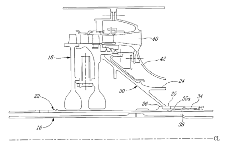
A gas turbine engine has a spool assembly including a compressor rotor and a turbine rotor connected by a first shaft. The first shaft has a forward end connected to the compressor rotor and an aft end connected to the turbine rotor. The first shaft extends concentrically around a second shaft. The first shaft forward end has a portion with an inner diameter of close tolerance with the second shaft. The second shaft has a region of enlarged diameter located axially aft of the compressor rotor but axially forward of the forward end of the first shaft. The region of enlarged diameter has a diameter greater than the inner diameter of the portion of close tolerance of the forward end of the first shaft to cause the region of enlarged diameter of the second shaft to engage the first shaft in interference in the event that the second shaft is moved axially aft relative to the first shaft more than a pre-selected axial distance.


French Abstract

Un moteur à turbine à gaz comprend un ensemble bobine pourvu dun rotor de compresseur et dun rotor de turbine reliés par un premier arbre. Le premier arbre présente une extrémité avant reliée au rotor de compresseur et une extrémité arrière reliée au rotor de turbine. Le premier arbre sétend de manière concentrique autour dun deuxième arbre. Lextrémité avant du premier arbre comporte une partie dont le diamètre intérieur présente une tolérance étroite par rapport au deuxième arbre. Le deuxième arbre comporte une région dun diamètre élargi situé axialement vers larrière du rotor de compresseur, mais axialement vers lavant de lextrémité avant du premier arbre. La zone où le diamètre est élargi présente un diamètre plus important que le diamètre intérieur de la partie de tolérance étroite de lextrémité avant du premier arbre afin que la région de diamètre élargi du deuxième arbre vienne en prise avec le premier arbre dans un ajustement serré au cas où le deuxième arbre est déplacé axialement vers larrière par rapport au premier arbre sur une distance supérieure à la distance axiale présélectionnée.

Claims

Note: Claims are shown in the official language in which they were submitted.


CLAIMS
1. A gas turbine engine comprising at least one spool assembly including at
least a
compressor rotor and a turbine rotor connected by a first shaft, the first
shaft
having a forward end connected to the compressor rotor and an aft end
connected
to the turbine rotor, the first shaft extending concentrically around a second
shaft,
the second shaft having a region of enlarged diameter located axially aft of
the
compressor rotor but axially forward of the forward end of the first shaft;
the
region of enlarged diameter having a diameter greater than an inner diameter
of at
least a portion of the forward end of the first shaft to cause the region of
enlarged
diameter of the second shaft to axially engage the first shaft in interference
in the
event that the second shaft is moved axially aft relative to the first shaft
more than
a pre-selected axial distance, wherein the first shaft is a high pressure
shaft and
the second shaft is a tie-shaft coupling the compressor rotor to the turbine
rotor
and, wherein a low pressure shaft extends concentrically within the tie-shaft;
the
low pressure shaft being connected at its aft end, beyond the tie-shaft to a
low
pressure turbine and at its front end, beyond the tie-shaft to a fan.
2. The gas turbine engine as defined in claim 1 wherein the spool assembly is
a high
pressure spool including a high pressure compressor and a high pressure
turbine
connected by the tie-shaft and the high pressure shaft.
3. The gas turbine engine as defined in claim 1 wherein a bell shape support
extends
forwardly from the forward end of the first shaft, the bell shaped support
abutting
the compressor rotor providing a conical contact zone and serving, in the case
of a
shaft shear, a centering effect on the compressor rotor, which provides axial
and
radial restraint to the rotor compressor rotor.
4. The gas turbine engine as defined in claim 3 wherein the first shaft is
provided
with a collar at the forward end thereof, the collar providing an axially
arresting
surface for the second shaft, the collar being coincident with the forward end
of
the first shaft at the point where the bell shaped support is formed.

5. A gas turbine engine comprising a low pressure spool assembly including at
least
a fan and a low pressure turbine connected by a low pressure shaft, a high
pressure spool assembly including at least a high pressure compressor rotor
and a
high pressure turbine rotor connected by a high pressure shaft and a tie-
shaft, the
high pressure shaft extending concentrically around the tie-shaft; the tie-
shaft
having a region of enlarged diameter located axially aft of the high pressure
compressor rotor but axially forward of a forward end of the high pressure
shaft,
the region of enlarged diameter configured to cause the region to engage the
high
pressure shaft in an interference fit in the event that the region is moved
axially
aft relative to the high pressure shaft more than a pre-selected axial
distance.
6. The gas turbine engine as defined in claim 5 wherein the region of enlarged

diameter is a radially projecting collar formed on the tic-shaft having a
diameter
greater than an internal diameter of the high pressure shaft at the location
of the
intended interference fit in the event of a tie-shaft shear upstream of the
forward
end of the high pressure shaft.
7. The gas turbine engine as defined in claim 6 wherein the high pressure
shaft
includes a bell shape support at the front end thereof abutting the high
pressure
compressor rotor, thus providing a conical contact zone and serving, in the
case of
a shaft shear, a centering effect on the compressor rotor, which provides
axial and
radial restraint to the rotor compressor rotor.
6

Description

Note: Descriptions are shown in the official language in which they were submitted.


GAS TURBINE ROTOR CONTAINMENT
TECHNICAL FIELD
The present application relates generally to gas turbine engines and more
particularly to
rotor containment for multi-shaft gas turbine engines.
BACKGROUND ART
A gas turbine engine is designed to safely shut down following the ingestion
of a
foreign object or blade loss event. Efficient design practice results in close
inter-shaft
clearances in concentric multi-shaft designs. The disturbance from these
events on the
rotor stability can lead to shaft-to-shaft rubbing at speeds and forces
sufficient to result in
separation of one or more affected shafts. The engine must be designed to
contain the
structure during subsequent deceleration of the rotors. The use of a full
length tie-shaft to
join the compressor and turbine rotor sections further complicates the
containment
design. Furthermore, if a shaft separation event occurs, separating loads such
as gas
pressure will tend to split the compressor and turbine rotor sections (i.e.
release of
compressor pressure tends to force the turbine rotor aft), further
complicating
containment by providing two rotating masses to contain.
SUMMARY
According to a general aspect, there is provided a gas turbine engine
comprising at least
one spool assembly including at least a compressor rotor and a turbine rotor
connected by
a first shaft, the first shaft having a forward end connected to the
compressor rotor and an
aft end connected to the turbine rotor, the first shaft extending
concentrically around a
second shaft, the second shaft having a region of enlarged diameter located
axially aft of
1
CA 2760454 2018-04-27

CA 02760454 2011-12-02
the compressor rotor but axially forward of the forward end of the first
shaft; the region
of enlarged diameter having a diameter greater than an inner diameter of at
least a portion
of the forward end of the first shaft to cause the region of enlarged diameter
of the second
shaft to axially engage the first shaft in interference in the event that the
second shaft is
moved axially aft relative to the first shaft more than a pre-selected axial
distance.
In accordance with a second aspect, there is provided a gas turbine engine
comprising a
low pressure spool assembly including at least a fan and a low pressure
turbine connected
by a low pressure shaft, a high pressure spool assembly including at least a
high pressure
compressor rotor and a high pressure turbine rotor connected by a high
pressure shaft and
a tie shaft, the high pressure shaft extending concentrically around the tie
shaft, the tie-
shaft having a region of enlarged diameter located axially aft of the high
pressure
compressor rotor but axially forward of a front end of the high pressure
shaft, the region
of enlarged diameter configured to cause the region to engage the high
pressure shaft in
an interference fit in the event that the region is moved axially aft relative
to the high
pressure shaft more than a pre-selected axial distance.
BRIEF DESCRIPTION OF THE DRAWINGS
Reference is now made to the accompanying figures in which:
Fig. 1 is a schematic cross-sectional view of a gas turbine engine
illustrating the multi-
shaft configuration; and
Fig. 2 is a partly fragmented axial cross-sectional view of a portion of a
high pressure
shaft and a tie shaft of the gas turbine engine shown in Fig. 1.
DETAILED DESCRIPTION
Fig. 1 schematically depicts a turbofan engine A which, as an example,
illustrates the
application of the described subject matter. The turbofan engine A includes a
nacelle 10,
a low pressure spool assembly which includes at least a fan 12 and a low
pressure turbine
14 connected by a low pressure shaft 16, and a high pressure spool which
includes a high
2

CA 02760454 2011-12-02
pressure compressor 18 and a high pressure turbine 20 connected by a tie-shaft
22 and a
high pressure shaft 24. The engine further comprises a combustor 26.
As can be seen more clearly in Fig. 2, the upstream end of the high pressure
shaft 24
terminates in a bell shaped support 30. The support 30 has a collar 35 having
an internal
diameter 35a that has a close radial tolerance with the tie-shaft 22. Threads
38 may be
provided on the outside diameter of the tie shaft 22 for engagement with a
threaded
coupling 34 axially downstream of collar 35 of the high pressure shaft 24. The
tie-shaft
22 includes a catcher 36, which may be provided as an integral portion of the
tie-shaft 22,
with an increased outer diameter portion that is at least greater than an
inside diameter
35a of the collar 35, depending from the high pressure shaft 24, through which
the tie-
shaft 22 extends.
The catcher 36 is located downstream of the high pressure compressor 18, but
axially
upstream of where the tie-shaft 22 enters the high pressure shaft 24, with
close axial
tolerances. Since the catcher 36 is radially larger than the inner diameter
35a of collar 35
of the high pressure shaft 24, the catcher portion 36 is too large to slide
axially through
the high pressure shaft 24. Axial movement of the catcher 36, aft relative to
the high
pressure shaft 24 will cause interference between the catcher 36 and the high
pressure
shaft collar 35, effectively restraining the tie-shaft 22 from moving
downstream relative
to high pressure shaft 24 which can be seen as joining the tie shaft 22 with
the high
pressure shaft 24.
It is to be understood that although the present embodiment relates to a tie-
shaft 22
arranged to be retained by the high pressure shaft 24, it is contemplated that
a similar
configuration can be designed with a low compressor shaft having a potential
interference
with a high pressure shaft in order to restrain the low pressure shaft in the
event of a rotor
imbalance and shaft separation.
It will be appreciated that, during a shaft shear event in which shaft rubbing
causes the
tic-shaft 22 to rupture or shear, separating loads such as gas pressure will
tend to split the
compressor and turbine rotor sections 18 and 20 (i.e. release of compressor
pressure tends
to force the turbine rotor 20 aft, relative to the compressor rotor 18). The
presence of the
3

CA 02760454 2011-12-02
catcher 36 on the tie shaft 22, however, continues to maintain the compressor
and turbine
rotors 18, 20 as a single mass, and hence will tend to draw the high
compressor rotor 18
aft during the event, along with the turbine rotor 20. Thus, rotor separation
is impeded.
Furthermore, the presence of the bell shaped support 30 on the high pressure
shaft 24
tends to have a centering effect on the high pressure compressor rotor 18. The

centralizing function provides a conical contact zone on the rotor 18, which
provides
axial and radial restraint. This reduces reliance on features such as seals
and aerofoils to
centralize the rotor if the mid rotor radial connection is lost and promotes
energy
dissipation between the set of more structurally capable rotating and static
components.
During a shaft separation event, as the compressor rotor 18 is drawn axially
rearward by
the rearward movement of the turbine rotor 20, multiple structures of the
engine, such as
the compressor diffuser 40, bearing housings, support cases 42, and gas-path
vane
structures will be crushed in sequence to absorb the energy in a manner so as
to
progressively arrest the rotor aft movement following the event. The
structures may be
closely coupled to the rotor through spacers or other adjusting features such
that the
rotating and static parts come into contact early after the event, to absorb
the kinetic
energy of the rotors by a set of crushable features of the components designed
to
plastically deform in a manner to protect surrounding hardware. In addition to
providing
containment, the engagement between static and rotating structures also
provides a
mechanical braking feature to preclude turbine rotational overspeed as the
stored energies
in the engine are exhausted in rundown.
The above description is meant to be exemplary only, and one skilled in the
art will
recognize that changes may be made to the embodiments described without
departing
from the scope of the invention disclosed. Any modifications which fall within
the scope
of the present invention will be apparent to those skilled in the art, in
light of a review of
this disclosure, and such modifications are intended to fall within the scope
of the
appended claims.
4

Representative Drawing
A single figure which represents the drawing illustrating the invention.
Administrative Status

For a clearer understanding of the status of the application/patent presented on this page, the site Disclaimer , as well as the definitions for Patent , Administrative Status , Maintenance Fee  and Payment History  should be consulted.

Administrative Status

Title Date
Forecasted Issue Date 2019-02-19
(22) Filed 2011-12-02
(41) Open to Public Inspection 2012-06-03
Examination Requested 2016-11-07
(45) Issued 2019-02-19

Abandonment History

There is no abandonment history.

Maintenance Fee

Last Payment of $263.14 was received on 2023-11-22


 Upcoming maintenance fee amounts

Description Date Amount
Next Payment if standard fee 2024-12-02 $347.00
Next Payment if small entity fee 2024-12-02 $125.00

Note : If the full payment has not been received on or before the date indicated, a further fee may be required which may be one of the following

  • the reinstatement fee;
  • the late payment fee; or
  • additional fee to reverse deemed expiry.

Patent fees are adjusted on the 1st of January every year. The amounts above are the current amounts if received by December 31 of the current year.
Please refer to the CIPO Patent Fees web page to see all current fee amounts.

Payment History

Fee Type Anniversary Year Due Date Amount Paid Paid Date
Application Fee $400.00 2011-12-02
Maintenance Fee - Application - New Act 2 2013-12-02 $100.00 2013-11-28
Maintenance Fee - Application - New Act 3 2014-12-02 $100.00 2014-10-07
Maintenance Fee - Application - New Act 4 2015-12-02 $100.00 2015-09-29
Request for Examination $800.00 2016-11-07
Maintenance Fee - Application - New Act 5 2016-12-02 $200.00 2016-11-22
Maintenance Fee - Application - New Act 6 2017-12-04 $200.00 2017-11-22
Maintenance Fee - Application - New Act 7 2018-12-03 $200.00 2018-11-27
Final Fee $300.00 2019-01-04
Maintenance Fee - Patent - New Act 8 2019-12-02 $200.00 2019-11-20
Maintenance Fee - Patent - New Act 9 2020-12-02 $200.00 2020-11-23
Maintenance Fee - Patent - New Act 10 2021-12-02 $255.00 2021-11-17
Maintenance Fee - Patent - New Act 11 2022-12-02 $254.49 2022-11-22
Maintenance Fee - Patent - New Act 12 2023-12-04 $263.14 2023-11-22
Owners on Record

Note: Records showing the ownership history in alphabetical order.

Current Owners on Record
PRATT & WHITNEY CANADA CORP.
Past Owners on Record
None
Past Owners that do not appear in the "Owners on Record" listing will appear in other documentation within the application.
Documents

To view selected files, please enter reCAPTCHA code :


To view images, click a link in the Document Description column. To download the documents, select one or more checkboxes in the first column and then click the "Download Selected in PDF format (Zip Archive)" or the "Download Selected as Single PDF" button.

List of published and non-published patent-specific documents on the CPD .

If you have any difficulty accessing content, you can call the Client Service Centre at 1-866-997-1936 or send them an e-mail at CIPO Client Service Centre.


Document
Description 
Date
(yyyy-mm-dd) 
Number of pages   Size of Image (KB) 
Abstract 2011-12-02 1 22
Description 2011-12-02 4 193
Claims 2011-12-02 2 87
Drawings 2011-12-02 2 29
Representative Drawing 2012-05-14 1 8
Cover Page 2012-05-31 2 46
Examiner Requisition 2017-11-06 3 222
Amendment 2018-04-27 5 210
Description 2018-04-27 4 192
Claims 2018-04-27 2 87
Final Fee 2019-01-04 2 67
Representative Drawing 2019-01-17 1 8
Cover Page 2019-01-17 1 41
Assignment 2011-12-02 4 180
Request for Examination 2016-11-07 2 70