Note: Descriptions are shown in the official language in which they were submitted.
CA 02760582 2011-10-31
PRESSURE-REDUCING GAS STORAGE DEVICE, GAS INJECTION
SYSTEM AND AUTOMOBILE
Technical Field
The present application relates to a pressure reducing gas storage device,
an air jet system and a motor vehicle.
Background
In order to avoid severe environmental pollution and directly utilize the
wind resistance airflow encountered by a motor vehicle during running, US
patent No. 7,641,005 B2 issued to the applicant of the present application
provides an engine comprising left and right wind-powered pneumatic engines
arranged symmetrically. Each of the left and right wind-powered pneumatic
engines comprises an impeller chamber as well as impeller and vanes arranged
therein. Compressed air is used in the engine as main power, and external wind
resistance are received for use as auxiliary power, thereby driving the
impellers
and vanes to operate to generate power output. The power drives the motor
vehicle after it is shifted via a central main power output gearbox.
The above invention firstly proposed a wind-powered pneumatic engine
which utilizes high pressure air as the main power and directly utilizes the
wind
resistance airflow as the auxiliary power, and a motor vehicle in which the
need
of converting wind resistance airflows into electrical power and the need of a
complex mechanic-electric energy conversion system are eliminated, and the
structure thereof is simplified. Therefore, a new way to save energy and find
a
substitute of fuel is provided.
In order to further optimize the performance of the wind-powered
pneumatic engine and improve the operating efficiency of the wind-powered
i
CA 02760582 2011-10-31
pneumatic engine and the motor vehicle, based on the aforementioned
application, another US patent application No. 12/377, 513 (WO 2008/022556)
filed by the applicant provides a combined wind-powered pneumatic engine.
This engine comprises left and right wind resistance engines operating
independently and a plurality of first compressed air engines arranged around
the left and right wind resistance engines. The left and right wind resistance
engines comprise a second impeller and the first compressed air engines
comprise a first impeller. The power outputted by the left wind resistance
engines and its peripheral first compressed air engines, as well as the power
outputted by the right wind resistance engine and its peripheral first
compressed air engines, is outputted as main power through a left power output
shaft, a right power output shaft, a reversing wheel and gear.
However, the above mentioned wind-powered pneumatic engine and
motor vehicle using compressed air as the source of main power are still a new
technology. Therefore, there remains a need of further perfection and
improvement to the structure of the wind-powered pneumatic engine and the
motor vehicle employing the wind-powered pneumatic engine as discussed
above. So is particularly in view of power performance.
Summary of the Invention
The object of the present application is to provide a pressure reducing gas
storage device, an air jet system and a motor vehicle which are capable of
continuously stable working.
In accordance with an aspect of the present application, a pressure
reducing gas storage device comprises a gas storage tank and a heat exchanger.
The gas storage tank comprises an inlet for receiving compressed air and an
outlet for outputting air. The heat exchanger is used to heat the air in the
air
2
CA 02760582 2011-10-31
input into the gas storage tank.
The pressure reducing gas storage device further comprises a pressure
reducing valve. The compressed air enters the gas storage tank after its
pressure
is reduced by the pressure reducing valve. The heat exchanger comprises a
first
heat exchange unit filled with a first medium. The first medium exchanges heat
with the air in the gas storage tank so as to heat the air. The pressure
reducing
gas storage device further comprises a cooler and a first circulating pump.
The
first heat exchange unit, the cooler and the first circulating pump form an
inner
circulating cooling system. The first medium circulates within the first heat
exchange unit and the cooler. The cooler exchanges heat with ambient air. The
first heat exchange unit has a first temperature regulation chamber which
surrounds the gas storage tank. The first medium is filled between the first
temperature regulation chamber and the gas storage tank. The two ends of the
cooler are connected to the temperature regulation chamber.
The heat exchanger further comprises a second heat exchange unit. The
inlet, the first heat exchange unit, the second heat exchange unit and the
outlet
are arranged in turn. The second heat exchange unit has a second temperature
regulation chamber, a second medium and a heater. The second temperature
regulation chamber surrounds the gas storage tank. The second medium is filled
between the second temperature regulation chamber and the gas storage tank.
The heater is provided on the second temperature regulation chamber and heats
the second medium. The second medium exchanges heat with the air in the gas
storage tank. The second temperature regulation chamber is connected to a
radiator and the second medium circulates within the second temperature
regulation chamber and the radiator. The radiator exchanges heat with ambient
air.
A motor vehicle refrigeration system comprises a gas storage tank, a
3
CA 02760582 2011-10-31
pressure reducing valve, a heat exchanger, a cooler and a first circulating
pump.
The gas storage tank receives compressed air the pressure of which is reduced
by a pressure reducing valve. The first heat exchange unit, the cooler and the
first circulating pump form an inner circulating cooling system. The first
medium circulates within the first heat exchange unit and the cooler. The
cooler
exchanges heat with ambient air.
A compressed air engine comprises a housing, an impeller body arranged
in the housing and an air jet system. The output of the air jet nozzle is used
to
eject compressed air onto the impeller body within the housing.
The pressure reducing valve comprises a housing, a valve core located
within the housing, an regulation block and an elastic body. The valve core is
sealingly and slidably fitted with the housing. The housing has a housing
cavity
axially running therethrough and an airway radially running therethrough. The
housing cavity is connected to an air intake pipeline by which the housing
cavity is connected to the gas storage tank. The valve core has a sealing end
and a regulation end and the elastic body is arranged between the regulation
block and the regulation end of the valve core. The regulation block is fixed
with the housing and the valve core has a first position and a second
position.
In the first position, the sealing end blocks the air intake pipeline to
disconnect
the air intake pipeline with the gas storage tank; and in the second position,
the
sealing end is apart from the air intake pipeline to connect the air intake
pipeline with the gas storage tank.
The pressure reducing valve comprises a first control valve and a second
valve. The first control valve comprises a first valve seat having a cavity, a
fist
valve plug, a second elastic body, a first gas pipeline, a second gas
pipeline, a
third pipeline and a fourth pipeline. The first valve plug is arranged in the
cavity and divides the cavity into a first chamber and a second chamber. The
4
CA 02760582 2011-10-31
first valve plug is sealingly and slidably fitted with the first valve seat.
The
second elastic body is arranged in the second chamber and supports the first
valve plug. The second gas pipeline connected to the first gas pipeline is
connected to the second chamber. The third gas pipeline connects the first
chamber with the second chamber. Both of the fourth gas pipeline and the first
gas pipeline are connected with the first chamber. The cross-sectional area of
the second gas pipeline is less than that of the third gas pipeline. The
second
control valve connected to the third gas pipeline controls the gas flow in the
third gas pipeline. The first valve plug has a first position and a second
position
along the sliding direction. At the first position the first valve plug blocks
the
first gas pipeline to disconnect the first gas pipeline and the first chamber,
and
at the second position the first valve plug departs from the first gas
pipeline to
connect the first gas pipeline with the first chamber.
An air jet system comprises a compressed air tank for storing compressed
air, a distributor for transporting compressed air to the compressed air
engine,
and a pressure reducing gas storage device. The output of the compressed air
tank is connected to an inlet of the pressure reducing gas storage device via
a
pipeline and the outlet of the pressure reducing gas storage device is
connected
to the distributor.
A motor vehicle comprises wheels, a drive train, a compressed air engine
and an air jet system. The air jet system, the compressed air engine, the
drive
train and the wheels are power connected in turn.
The present application has the following technical effects. When the
applicant of this application tested a motor vehicle using a compressed air
engine, he found that the power of the motor vehicle is usually insufficient
after
running a long time. In this case, the applicant had to stop testing and check
each part of the motor vehicle, but he failed to find the malfunction until he
5
CA 02760582 2011-10-31
once found that the air-jet nozzle was condensed and frozen so that it cannot
normally eject gas. Based on an analysis of the above situation, the applicant
further found that the pressure reducing valve is also easy to be frozen. As
for
this case, the phenomenon of being frozen is eliminated by providing a heat
exchanger to heat the air input in the gas storage tank. In addition, by
providing
a cooler, the temperature of ambient air is reduced and energy is saved. By
providing a heater, not only the working stability of compressed air is
further
improved, but also the heating of the motor vehicle is achieved.
BRIEF DESCRIPTION OF THE DRAWINGS
Fig. 1 is a schematic structural view showing the connection of a
compressed air tank, an air jet system and a compressed air engine of a motor
vehicle.
Fig. 2 is a schematic structural view showing the air pressure regulator of
the motor vehicle at a close configuration.
Fig. 3 is a schematic structural view showing the air pressure regulator of
the motor vehicle at an open configuration.
Fig. 4 is a sectional view along the line A-A in Fig. 3.
Fig. 5 is a schematic structural view of the motor vehicle (only two wheels
are illustrated).
Fig. 6 is a top schematic view of the motor vehicle.
Fig. 7 is a top schematic view showing a wind resistance engine and a
compressed air engine assembled together.
Fig. 8 is a front schematic view showing the wind resistance engine and
the compressed air engine assembled together.
Fig. 9 is a front schematic view of a compressed air engine of the motor
vehicle.
6
CA 02760582 2011-10-31
Fig. 10 is a top schematic view of the compressed air engine of the motor
vehicle.
Figs. 11 and Fig. 12 are schematic diagrams respectively illustrating a
wind resistance engine and a compressed air engine connected in parallel and
in
series.
Fig. 13 is a schematic structural view of a nozzle.
Fig. 14 is a top view of a motor vehicle according to a second
embodiment.
Fig. 15 is a top view of a motor vehicle according to a third embodiment.
Fig. 16 is a top view of a motor vehicle according to a fourth embodiment.
Fig. 17 is a schematic structural view showing a flow regulating valve
being closed according to the fifth embodiment.
Fig. 18 is a schematic structural view showing a flow reducing valve being
opened according to the fifth embodiment.
Fig. 19 is a schematic structural view illustrating a connection relationship
among a flow reducing valve, a compressed air tank, a distributor and a
transmission mechanism according to the fifth embodiment.
Fig. 20 is a top view of a motor vehicle utilizing another kind of wind
resistance engine.
Figs. 21-23 are front sectional view, side sectional view and top view of
the wind resistance engine in Fig. 20.
DETAILED DESCRIPTION
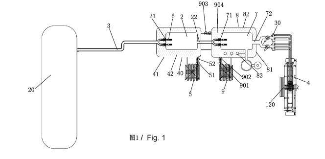
As shown in Fig. 1 to Fig. 8, a motor vehicle according to this
embodiment comprises an air jet system, a compressed air engine 4, wind
resistance engines 3, 3', a drive train 11 and wheels 123. The air jet system
has
an air jet nozzle 60 and the compressed air engine 4 has a primary power
7
CA 02760582 2011-10-31
output shaft 120. The air jet nozzle 60 of the air jet system ejects gas to
the
compressed air engine 4. The compressed air engine 4 compresses gas and then
expands gas so that the primary power output shaft 120 of the compressed air
engine 4 is driven to rotate, which drives the wheels 123 to rotate via the
drive
train 11. The drive train 11 may comprise a gearbox 112, a universal
transmission device 113 connected to the gearbox 112, and a drive axle 114
connected to the universal transmission device 113. A first clutch 56 is
provided
between the primary power output shaft 120 of the compressed air engine 4 and
the drive train 11. The drive axle 114 is connected to the wheels 123.
As shown in Fig. 1 to Fig. 4, the air jet system comprises a compressed air
tank 20 for storing compressed air, a pressure reducing gas storage device, a
distributor 30 and the air jet nozzle 60. The output of the compressed air
tank
is connected to an inlet of the pressure reducing gas storage device via a
pipeline 3. The outlet of the pressure reducing gas storage device is
connected
15 to the air jet nozzle 60 via the distributor 30. The distributor 30 is used
to
distribute the gas outputted by the pressure reducing gas storage device into
multiple routes of gas, each of which is ejected by a corresponding air jet
nozzle 60. The pressure reducing gas storage device comprises a gas storage
tank and a heat exchanger. The gas storage tank comprises a first air chamber
2
20 having a first inlet 21 and a first outlet 22. The first inlet 21 is used
to input air
and the first outlet 22 is used to output air. The two ends of the pipeline 3
are
connected to the compressed air tank 20 and the first inlet 21 of the first
air
chamber 2, respectively. There may be provided one or more pipelines 3. The
cross section area of the pipeline 3 is less than that of the compressed air
tank
20 and less than that of the first air chamber 2. The heat exchanger comprises
a
first heat exchange unit 40 arranged on the first air chamber 2. The first
heat
exchange unit 40 comprises a first temperature regulation chamber 41
8
CA 02760582 2011-10-31
surrounding the first air chamber 2 and a first medium 42 filled between the
first temperature regulation chamber 41 and the first air chamber 2. The first
medium 42 may be liquid (for example, water) or gas or other heat
exchangeable mediums. The temperature of the first medium 42 is higher than
that of the gas within the first air chamber 2 so that the compressed air in
the
compressed air tank 20 is released into the first air chamber 2 via the
pipeline 3
and then exchanges heat with the first medium 42. The heated air is output
from
the first outlet 22 of the first air chamber 2. The first air chamber 2 may be
made of a material having good heat conduction property so as to facilitate
the
heat exchange of the air in the first air chamber 2 with the first medium 42.
The
first temperature regulation chamber 41 may be made of a material which is
thermal insulation or has poor heat conduction property so that the heat is
difficult to be dissipated into the ambient air.
The first heat exchange unit 40 is connected to a cooler 5. Each of the two
ends of the cooler 5 is connected to the first temperature regulation chamber
41
to form a refrigeration cycle loop. The cooler 5 is provided with a first
circulating pump 51 and a first circulating pump switch 52 for controlling the
switch of the first circulating pump 51. The temperature of the first medium
42
in the first temperature regulation chamber 41 decreases after the first
medium
42 exchanges heat with the air in the first air chamber 2. The first medium 42
of
which the temperature is decreased circulates in the cooler 5 and the first
temperature regulation chamber 41. A refrigeration air-conditioning circulates
the ambient air to exchange heat with the cooler 5 so that the ambient air is
cooled to achieve refrigeration effect.
The air output from the compressed air tank 20 is ejected via the air jet
nozzle 60 after it is heated by the first heat exchange unit 40 of the
pressure
reducing gas storage device so that condensation or even freeze will not be
9
CA 02760582 2011-10-31
occurred at the air jet nozzle 60 due to lower temperature. Meanwhile, the
effect of decreasing the temperature of ambient air is achieved by connecting
the first heat exchange unit 40 to the refrigeration air-conditioning and
using
the first medium 42 whose temperature has been decreased as circulating
medium. Therefore, energy is saved.
As shown in Fig. 2 to Fig. 4, the air jet system may further comprise an air
pressure regulator 6 for maintaining the air pressure in the first air chamber
2 at
a predetermined value. The air pressure regulator 6 comprises a housing 610, a
valve core 620, an elastic body 630, a locking block 640 and a regulating
block
650. The housing 610 is mounted at the first inlet 21 of the first air chamber
2
via a fastener 14. The housing 610 is partly located within the first air
chamber
2 and partly extends out of the first air chamber 2. The housing 610 has a
housing cavity 611 axially running therethrough and an airway 612 radially
running therethrough. The housing cavity 611 is in communication with an air
intake pipe 613 which is in communication with the pipeline 3. The airway 612
is in communication with the first air chamber 2. The valve core 620 is
located
within the housing cavity 611 and sealingly and slidably fitted with the
housing.
Two ends of the valve core 620 in the axial direction of the housing 610 are a
sealing end 621 and a regulation end 622. The sealing end 621 may seal the
airway 612 and the air intake pipe 613. The elastic body 630 may be capable of
deforming expansively along the axial direction of the housing 610. Two ends
of the elastic body 630 bear against the regulation end 622 of the valve core
620 and the regulating block 650, respectively. The regulating block 650 is
thread connected to the housing 610, and the locking block 640 is thread
connected to the housing 610 and presses the regulating block 650 against the
elastic body 630. The regulating block 650 and the locking block 640 have
axially running through first and second lead holes 651, 641, respectively.
The
CA 02760582 2011-10-31
first and second lead holes 651, 641 communicate with each other to guide gas
into the housing cavity 611 and onto the regulation end 622 of the valve core
620. The diameter of the first lead hole 651 is less than that of the second
lead
hole 641. The sealing end 621 of the valve core is in the form of truncated
cone,
and an elastic sealing ring 623 is fixed on the contour surface of the sealing
end
621. An elastic sealing ring 623 is also fixed on the contour surface of the
regulation end of the valve core. On the section perpendicular to the axis of
the
housing 610, the cross section area of the sealing end 621 of the valve core
is
less than that of the regulation end 622. The pressure applied on the sealing
end
621 includes the air pressure of the air input from the pipeline 3, and the
pressure applied on the regulation end 622 includes the air pressure of the
air in
the first air chamber 2 and the elastic force of the elastic body 630. The
elastic
body is for example a spring, or other components capable of deforming
expansively along the axis direction of the housing 610.
The working principle of the air pressure regulator is described below.
When the air pressure of the gas input via the pipeline 3 is stable, a
pressure
reducing passage 614 is formed between the valve core 620 and the housing
610 so that the gas in the pipeline 3 can enter the first air chamber 2
through the
pressure reducing passage 614 and the airway 612. When the air pressure of the
gas input via the pipeline 3 is higher than a predetermined value, the air
pressure of the input gas pushes the valve core 620 to move toward the side of
the regulation end 622, and thereby the volume of the pressure reducing
passage 614 increases and the air pressure in the first air chamber 2
decreases.
When the air pressure of the gas input via the pipeline 3 is lower than the
predetermined value, the force applied to the regulation end 622 is larger
than
that applied to the sealing end 621 so that the valve core moves toward the
side
of the sealing end 621, and thereby the volume of the pressure reducing
passage
11
CA 02760582 2011-10-31
614 decreases and the air pressure in the first air chamber 2 increases. When
the
air pressure of the gas input via the pipeline 3 changes, the valve core moves
linearly according to the variation of the forces applied to the sealing end
621
and the regulation end 622 so as to stabilize the air pressure in the first
air
chamber 2 at a predetermined air pressure. When the air pressure regulator is
turned off, the sealing end 621 blocks the airway 612 and the air intake pipe
613 and the gas in the pipeline 3 cannot enter the first air chamber 2. The
air
pressure of the gas outputted by the pressure reducing gas storage device can
be
stabilized at a predetermined air pressure by providing the air pressure
regulator.
The prestressing force of the elastic body 630 may be adjusted by
screwing or unscrewing the regulation block 640 so that the initially set air
pressure of the air pressure regulator may be changed.
The pressure reducing gas storage device may further comprise a second
air chamber 7 and a second heat exchange unit 8. In the direction of airflow,
the
first air chamber 2 is in front of the second air chamber 7. The second air
chamber 7 has a second inlet 71 and a second outlet 72. The second inlet 71 is
connected to the first outlet 22 of the first air chamber 2. The second heat
exchange unit 8 comprises a second temperature regulation chamber 81
surrounding the second air chamber 7, a second medium 82 such as liquid or
gas filled between the second temperature regulation chamber 81 and the
second air chamber 7, and a heater 83 for heating the second medium 82. The
heater 83 is for example, a solar energy heater, electrical heater, microwave
heater or other heaters capable of heating a medium. There can be provided one
or more heaters and there also can be provided one or more kinds of heaters.
The second temperature regulation chamber 81 is connected to a radiator 9 of a
heating air-conditioning to form a heating cycle loop. The radiator 9 is
provided
12
CA 02760582 2011-10-31
with a second circulating pump 901 and a second circulating pump switch 902
for controlling the switch of the second circulating pump 901. The heated
second medium 82 circulates within the second temperature regulation chamber
81 and the radiator 9. The heating air-conditioning circulates ambient air to
exchange heat with the radiator 9 so that the temperature of ambient air
increases to achieve the effect of heating. The air may be further heated by
the
second heat exchange unit 8 after being heated by the first heat exchange unit
40, so that it is more difficult to condense or even freeze the air jet nozzle
of
the air jet system. The second inlet 71 of the second air chamber 7 may also
be
provided with a pressure reducing valve 6.
In addition, the first temperature regulation chamber 41 and the second
temperature regulation chamber 81 are connected via a pipeline to form a cycle
loop. This cycle loop is provided with a third circulating pump 903 and a
third
circulating pump switch 904 for controlling the switch of the third
circulating
pump 903.
The heat exchanger may only comprise a first heat exchange unit which
heats air in an air storage tank by means of heat exchange. There can be
provided one or more first heat exchange units. The heat exchanger may also
only comprise a second heat exchange unit having a heater. There can be
provided one or more second heat exchange units. The heat exchanger may also
comprise both of the first and second heat exchange units. When the first heat
exchange unit is used, not only air may be heated, but also the cooled first
medium may be used as medium to reduce the temperature in the motor vehicle.
When the second heat exchange unit is used, the heated second medium may be
used as medium to increase the temperature in the motor vehicle.
As shown in Fig. 6 to Fig. 8, there are provided two wind resistance
engines arranged symmetrically, namely, a first wind resistance engine 3 and a
13
CA 02760582 2011-10-31
second wind resistance engine 3'. The first wind resistance engine comprises a
first casing 117, a first impeller chamber 43 enclosed by the first casing
117, a
plurality of first impellers 44 and a first impeller shaft 45. Each of the
first
impellers 44 is fixed on the first impeller shaft 45 and located within the
first
impeller chamber 43. The first casing 117 is provided with a first air intake
1
for receiving front resistance fluid during the running of the motor vehicle.
The
first air intake 1 has an external opening and an inner opening. The caliber
of
the external opening is larger than that of the inner opening. The first air
intake
1 communicates with the first impeller chamber 43. The resistance fluid is
directed into the first impeller chamber 43 via the first air intake 1 to
drive the
first impellers 44 and the first impeller shaft 45 to rotate. Auxiliary power
is
output via the first impeller shaft 45. The second wind resistance engine 3'
comprises a second casing 117', a second impeller chamber 43', a second
impeller 44', a second impeller shaft 45' and a second air intake 1' for
receiving
resistance fluid. The first impeller chamber 43 and the second impeller
chamber
43' are arranged independently and do not communicate with each other. The
first impeller shaft 45 is parallel with the second impeller shaft 45' and
rotates
in an opposite direction to the second impeller shaft 45'. A first transfer
gear 46
is fixed on the first impeller shaft 45 and a second transfer gear 118 is
fixed on
the second impeller shaft 45'. The motor vehicle further comprises a first
reversing device, a second reversing device and an auxiliary power output
shaft.
The first reversing device comprises a reversing gear 119 and a transmission
belt 47 and the second reversing device comprises a first drive conical gear
49
and a second drive conical gear 50. The first drive conical gear 49 engages
with
the second drive conical gear 50 and the axis of the first drive conical gear
49 is
perpendicular to that of the second drive conical gear 50. The reversing gear
119 engages with the first transfer gear 46 and the axis of the reversing gear
14
CA 02760582 2011-10-31
119 is parallel with that of the first transfer gear 46. The transmission belt
47 is
wound around the first drive conical gear 49, the second transfer gear 118 and
the reversing gear 119 which are arranged triangularly. The first drive
conical
gear 49 is fixed on an auxiliary power output shaft 130. The power outputted
by
the first impeller shaft 45 and the second impeller shaft 45' is switched onto
the
auxiliary power output shaft 130 via the first reversing device, and the power
outputted by the auxiliary power output shaft 130 is switched to the drive
train
11 of the motor vehicle via the second reversing device. There may be two, one
or more than two wind resistance engines. A plurality of impellers fixed on
the
impeller shafts are mounted in the impeller chamber of the wind resistance
engine and the impellers and impeller shafts are driven to rotate by the
resistance fluid.
After the power outputted by the impeller shafts of the wind resistance
engine is reversed via the reversing device, it may directly drive the drive
train
of the motor vehicle, as shown in Fig. 11, and it may also be connected in
series
with the primary power output shaft of the compressed air engine to drive the
drive train of the motor vehicle, as shown in Fig. 12.
As shown in Fig. 6 to Fig. 8, The compressed air engine 4 is arranged to
be independent of the first and second wind resistance engines 3, 3' and
located
at the back of the first and second wind resistance engines 3, 3'. The
compressed air engine 4 has the primary power output shaft 120 and the second
transfer gear 50 is fixed at the end of the primary power output shaft 120.
With
the first and second drive conical gears 49, 50 which are vertically engaged
with each other, the power, which is outputted by the first and second wind
resistance engines 3, 3', is reversed vertically and outputted to the primary
power output shaft 120 of the compressed air engine.
The motor vehicle is provided with a first clutch 160 via which the power
CA 02760582 2011-10-31
outputted by the first and second wind resistance engines 3, 3' is output to
the
auxiliary power output shaft 130, as shown in Fig. 8. During the starting
stage
of the motor vehicle, the wind resistance engine does not output power and the
first clutch 160 disengages so that the auxiliary power output shaft 130 would
not be rotated with the primary power output shaft 120, thus reducing the
starting load of the motor vehicle. During the normal running of the motor
vehicle, the first clutch 160 engages, the power outputted by the auxiliary
power output shaft 130 and that outputted by the primary power output shaft
120 together drive the drive train 11 of the motor vehicle. The first clutch
160
may be for example a prior art one-way clutch, overrunning clutch, etc, and of
course may also be other clutches having disengaging and engaging states.
As shown in Fig. 6 to Fig. 10, the compressed air engine 4 further
comprises a housing and a round impeller body 74 located within the housing
70. The housing comprises an annular side casing 72, an upper cover plate 73
and a lower cover plate 73'. The upper cover plate 73 and lower cover plate
73'
are respectively fixed at the upper and lower openings of the annular side
casing 72 so that the annular side casing 72, the upper cover plate 73 and
lower
cover plate 73' form a closed impeller body chamber 68. The impeller body 74
is located within the impeller body chamber 68 and the central portion of the
impeller body 74 is fitted on the primary power output shaft 120. By notching
on the circumference surface of the impeller body 74 which joints with the
inner surface of the side casing 72, a set of working chambers 69 are formed
and distributed evenly around the axis of the primary power output shaft 120.
On the section perpendicular to the axis of the primary power output shaft
120,
the working chamber 69 takes a form of a triangle formed by three curves
connected end to end. There may be one or more sets of working chambers 69.
The working chambers may be a thorough-slot structure axially running
16
CA 02760582 2011-10-31
through on the impeller body. The inner surfaces of the upper cover plate, the
lower cover plate and the side casing close the working chamber. The working
chambers may also be of a non-thorough-slot structure provided in the middle
of the circumference surface of the impeller body and the inner surface of the
side casing closes the working chambers. Of course, the working chamber may
also be closed by the inner surfaces of the upper cover plate and the lower
cover plate, or by the inner surfaces of the lower cover plate and the side
casing.
That is to say, the working chambers are closed by the inner surface of the
casing.
The inner surface of the side casing 72 is also provided with a plurality of
ejecting inlets 67 and a plurality of ejecting outlets 64. The ejecting inlets
67
and ejecting outlets 64 are arranged alternately. An annular first-order
silencer
chamber 63 is also provided within the side casing 72. A plurality of first-
order
exhaust ports 65 are provided on the external surface of the side casing 72,
and
each of the ejecting outlets 64 has a corresponding first-order exhaust port
65.
The ejecting outlets 64 communicate with the first-order exhaust ports 65 via
the first-order silencer chamber 63. The ejecting inlets 67 communicates with
none of the ejecting outlets 64, the first-order exhaust port 65 and the first-
order
silencer chamber 63. The ejecting outlets 64 and their corresponding first-
order
exhaust port 65 are spaced at an angle on the circumference centered on the
axis of the primary power output shaft 120. An air jet nozzle seat 71 is fixed
on
the position corresponding to each of the ejecting inlets 67 on the side
casing
72. Each air jet nozzle seat 71 is fixed with two air jet nozzles 60. Each of
the
air jet nozzles 60 extends into the corresponding ejecting inlet 67 and is
connected to a gas ejecting pipe 54, and the axes of the two air jet nozzles
60
on each of the ejecting inlets 67 form an acute angle. The compressed air in
the
compressed air tank 20 is transferred into the working chambers 69 via the gas
17
CA 02760582 2011-10-31
ejecting pipe 54 and the air jet nozzle 60. For each working chamber 69, the
air
ejected by the air jet nozzle 60 drives the impeller body 74 to rotate and is
compressed to be temporarily stored in the working chambers 69. When
moving to the ejecting outlets 64, the temporarily stored gas in the working
chamber 69 expands and jets out from the ejecting outlets 64 at a high speed.
The reaction force formed when the gas is ejected again drives the impeller
body 74 to rotate. When the impeller body 74 rotates, the primary power output
shaft 120 is driven to rotate, which further drives the drive train 11 of the
motor
vehicle.
For each working chamber 69, it takes a period of time from receiving the
gas ejected by the air jet nozzle 60 to ejecting the gas from the ejecting
outlets
64. During the period of time, the gas is compressed and temporarily stored in
the working chamber 69 so that the reaction force formed when the gas is
ejected is larger and thus more power can be provided for the motor vehicle.
Since the working chamber 69 is closed by the inner surface of the housing, it
facilitates the compression and temporary storage of the compressed gas. In
addition, in order to prevent the compressed gas from being condensed when
being input to the compressed air engine, the air jet nozzle seat 71 may be
provided with a first heater 77 for heating the air jet nozzle 60. The first
heater
77 may be an electrically heated wire which is embedded in the air jet nozzle
seat 71. As shown in Fig. 13, the air jet nozzle 60 comprises an air jet
nozzle
body 617 having an axially running through cavity 618. The air jet nozzle body
617 is provided with a second heater 615. The second heater 615 is an
electrically heated wire which is wounded around the air jet nozzle body 617.
The air jet nozzle body is also provided with a heat insulation layer 616. The
second heater 615 is located between the heat insulation layer 616 and the
air-jet nozzle body 617. The first and second heaters may be selected from a
18
CA 02760582 2011-10-31
group consisting of an electrical heater, a microwave heater and a solar
energy
heater.
The motor vehicle further comprises a first electromotor 53 which is
power connected with the primary power output shaft 120 of the compressed
air engine 4 via a belt transmission mechanism 51. The belt transmission
mechanism 51 comprises a pulley 511 and a belt 512 wounded around the
pulley 511.
As shown in Fig. 6 to Fig. 8, the motor vehicle further comprises a
compressed air reuse system for communicating the first-order exhaust ports 65
of the compressed air engine with the impeller chambers 43, 43' of the wind
resistance engines. The compressed air reuse system comprises a first-order
exhaust pipe 57, a second-order silencer chamber 59 and a second-order
exhaust pipe 58. The inlets of the first-order exhaust pipe 57 communicate
with
the first-order exhaust ports 65, respectively, and the outlets of the first-
order
exhaust pipe 57 are gathered to the second-order silencer chamber 59. The
second-order silencer chamber 59 communicates with the inlets of the
second-order exhaust pipe 58. The outlets of the second-order exhaust pipe 58
communicate with both of the first impeller chamber 43 and the second
impeller chamber 43'. The was ejected at a high speed from the ejecting
outlets
64 of the compressed air engine passes through the first-order silencer
chamber
63 and the first-order exhaust port 65 in turn, then enters the first-order
exhaust
pipe 57 and after being silenced by the second-order silencer chamber 59,
finally enters the first and second impeller chambers 43, 43' to drive the
first
and second impellers to rotate so as to reuse the compressed air. Accordingly,
energy can be saved effectively and the driving force of the motor vehicle can
be further improved.
Fig. 14 illustrates a second embodiment of the motor vehicle, which
19
CA 02760582 2011-10-31
differs from the first embodiment mainly in that the first and second wind
resistance engines 3, 3' are of horizontal type mounting and the first and
second
impeller shafts 45, 45' are mounted horizontally and perpendicular to the
primary power output shaft 120. In the first embodiment, the first and second
wind resistance engines 3, 3' are of vertical type mounting and the first and
second impeller shafts 45, 45' are mounted vertically, as shown in Fig. 8. As
for
the second embodiment, although the power outputted by the first and second
impeller shafts of the first and second wind resistance engines is converted
to
be coaxially output after being firstly reversed, it cannot be directly
transferred
to the drive train since the rotation direction of the coaxial output is
perpendicular to that required by the drive train. It is necessary to use a
second
reversing device to convert the power outputted by the first and second wind
resistance engines to the rotation direction which is identical to the
rotation
direction of the drive train.
Fig. 15 illustrates a third embodiment of the motor vehicle, which differs
from the first embodiment mainly in that a second clutch 111 is provided
between the auxiliary power output shaft 130 commonly used by both of the
first and second wind resistance engines 3, 3' and the primary power output
shaft 120 of the compressed air engine 4. The power connection or
disconnection of the wind resistance engines and the wind resistance engine
may be performed by the second clutch 111. The wind resistance engines
according to this embodiment are of horizontal type mounting.
As shown in Fig. 16 to Fig. 19, a pressure reducing valve 40 is arranged
between the distributor 30 and the compressed air tank 20 of the motor
vehicle.
The pressure reducing valve 40 comprises a first control valve 300 and a
second control valve 400. The first control valve 300 comprises a first valve
seat 301, a first valve plug 302 and an elastic body 303. The first valve seat
301
CA 02760582 2011-10-31
has a cavity 304. The first valve plug 302 is arranged in the cavity 304 and
is
slidably and sealingly fitted with the first valve seat 301. The first valve
plug
302 is located in the cavity 304 and divides the cavity 304 into a first
chamber
305 and a second chamber 306. The first control valve 300 further comprises a
first gas pipeline 307, a second gas pipeline 308, a third gas pipeline 309
and a
fourth gas pipeline 310. The first gas pipeline 307 is used to receive the
compressed air input from the compressed air tank 20. The second gas pipeline
308 communicates at one end with the first gas pipeline 307, and at the other
end with the second chamber 306. The third gas pipeline 309 communicates at
one end with the second chamber 306, and at the other end with the first
chamber 305. The first chamber 305 is connected to the distributor 30 via the
fourth gas pipeline 310. The first gas pipeline 307 has a diameter greater
than
that of the second gas pipeline 308 and that of the third gas pipeline 309,
and
the second gas pipeline 308 has a diameter less than that of the third gas
pipeline 309. The first valve plug 302 has a close position and an open
position
with respect to the first valve seat 301. When the first valve plug 302 is at
the
close position, it blocks the junction between the first gas pipeline 307 and
the
first chamber 305, so that the first gas pipeline 307 is disconnected from the
first chamber 305; and when the first valve plug 302 is at the open position,
it is
apart from the junction between the first gas pipeline 307 and the first
chamber
305 so that the first gas pipeline 307 communicates with the first chamber
305.
The first valve plug 302 comprises a columnar main body 311 and a
closing portion 312 with a less diameter than that of the main body 311 and
having a needle-shaped head. The main body 311 is slidably fitted with the
first
valve seat 301. The periphery surface of the main body 311 is surrounded by a
first elastic sealing ring 316, through which the main body 311 is sealingly
fitted with the first valve seat 301. The main body 311 has an axially running
21
CA 02760582 2011-10-31
through inner chamber 317 in which the closing portion 312 extending into the
chamber 305 is disposed and linearly movable with respect to the main body
311. The elastic body 303 comprises a first elastic body 313 and a second
elastic body 314. The first elastic body 313 is disposed in the inner chamber
317, with its two ends bearing against the closing portion 312 and a
positioning
block 315, respectively. The second elastic body 314 is disposed in the second
chamber 306 and is fixed at one end to the bottom 301 a of the first valve
seat
301 and at another end to the positioning block 315. The positioning block 315
is fixed through thread fitting to the bottom of the inner chamber 317. A
second
elastic sealing ring 318 is fixed onto the top surface of the main body 311.
The second control valve 400 is disposed on the third gas pipeline 309 for
controlling the gas flux in the third gas pipeline 309. The control on gas
flux
may comprise controlling changes between flow and non-flow as well as
between large flow and small flow. The second control valve 400 comprises a
second valve seat 401 and a second valve plug 402. The second valve plug 402
comprises a second main body 404 and a conical body 405 located at the front
end of the second main body 404. The second valve seat 401 is provided with a
gas passage 406 having a gas inlet 407 and a gas outlet 408, both of which are
connected with the third gas pipeline 309. A control cavity 410 which is
cone-shaped corresponding to the cone body is provided within the gas passage
406. The second main body 404 is thread fitted with the control cavity 410 so
that a second gap 403 between the second main body 403 and the control cavity
410 can be adjusted through the thread, thereby a gas flux in the third gas
pipeline 309 is controlled. It can be understood for the persons in the art
that
the second control valve 400 may be implemented by other conventional
airflow control means. The second valve plug 402 is connected to the output
port of a transmission mechanism 500, and the input port of the transmission
22
CA 02760582 2011-10-31
mechanism 500 is coupled with a control switch of a motor vehicle. The
transmission mechanism 500 comprises a second transmission mechanism 502
and a power connected first transmission mechanism 501 connecting the
control switch with the second transmission mechanism 502. The second
transmission mechanism 502, such as a belt transmission mechanism,
comprises a driving pulley 503 and a driven pulley 504 having a less diameter
than that of the driving pulley 503. A belt 505 is wound around the driving
pulley 503 and the driven pulley 504. The first transmission mechanism 501
moves according to an operation of the control switch to drive the driving
pulley 503 to rotate, which further drives the driven pulley 504 to rotate by
means of the belt 505. The driven pulley 504 drives the second valve plug 402
to rotate, rendering the second valve plug 402 screwed or unscrewed with
respect to the second valve seat 401. In other words, the regulation of the
flux
of the third gas pipeline is carried out by changing size of the second gap
403
between the first valve plug and the first valve seat. When the second gap 403
becomes zero, the second control valve 400 is closed, and the third gas
pipeline
309 is disconnected.
When the compressed air does not enter the pressure reducing valve, the
head of the closing portion 312 blocks the junction between the first gas
pipeline 307 and the first chamber 305 under the elastic force of the first
and
second elastic body 313, 314. At this moment, there is a gap between the
second sealing ring 318 and the top 301b of the first valve seat 301 (or the
second sealing ring 318 has reached the top 301b). When the compressed air
enters the pressure reducing valve, the compressed air aerates into the
chamber
306 through the first gas pipeline 307 and the second gas pipeline 308. During
aeration, if the control switch 7 is not turned on, the pressure of the second
chamber 306 continues driving the first valve plug 302 to move toward the top
23
CA 02760582 2011-10-31
301b, allowing the head of the closing portion to block up the junction (a
peripheral surface 320 of the closing portion 312 clings to the inner wall 321
of
the first gas pipeline 307) stably, until the second sealing ring 318 bears
against
the top 301b (or the second sealing ring 318 presses against the top 301b
after
being elastically deformed). When the control switch 7 is turned on, the
second
valve plug 402 is unscrewed, allowing the third gas pipeline 309 to be
unblocked, and gas in the second chamber 306 flows to the first chamber 305
through the third gas pipeline 309, rendering a reduction of the pressure in
the
second chamber 306. The pressure of the compressed air forces the closing
portion 312 of the first valve plug 302 to leave the junction, allowing the
compressed air to enter the distributor 30 through the first chamber 305 and
the
fourth gas pipeline 310. While the compressed air is entering the fourth gas
pipeline 310 through the first chamber 305, the whole first valve plug 302
moves toward the bottom 301a of the first valve seat 301. When forces applied
to the first valve plug 302 become equilibrium, the main body 311 and the
closing portion 312 stay still with respect to each other. A first gap 319 for
passage of the compressed air is then formed between the periphery surface 320
of the closing portion and the inner wall 321 of the first gas pipeline. While
the
compressed air tank stops supplying gas, the closing portion of the first
valve
plug blocks the junction between the first gas pipeline and the first chamber
again under forces applied by the first and second elastic body, with the
closing
portion clinging to the inner wall of the first gas pipeline.
The flux and pressure of gas in the third gas pipeline may be regulated
through operation of the second control valve, which makes the closing portion
move up or down and leads to change of the first gap between the inner wall of
the first gas pipeline and the periphery surface of the closing portion,
thereby
regulating the flux and pressure of gas in the fourth gas pipeline.
24
CA 02760582 2011-10-31
The first, second and third elastic bodies may be for example a spring, or
an elastic sleeve, clips, or other components capable of deforming expansively
or elastically along the sliding direction of the first valve plug.
With such a pressure reducing valve, compressed air in the compressed air
tank is output to the distributor after the air pressure is regulated. The
second
elastic body 313 acts as a buffer effectively reducing a rigid strike force
between the first valve plug 302 and the first valve seat 301, and meanwhile
improving the air tightness provided by the closing portion 312 to the first
gas
pipeline 307. Since the second gas pipeline 308 has a cross section area less
than that of the third gas pipeline 309, control on the whole gas path of the
control valve 300 can be achieved, and meanwhile a flux can be amplified so as
to improve precision of control.
When two distributors are provided, two pressure reducing valves are
provided corresponding to the two distributors and controlled by the same
control switch. In this situation, as shown in Fig. 19, the second
transmission
mechanism comprises two driven pulleys separately driving the second valve
plugs of the two pressure reducing valves. In other examples, more than two
pressure reducing valves in series may be provided in order to achieve
multistage control of the compressed air input to the gas distributor.
In addition, as shown in Fig. 16, the pressure reducing valve may be
arranged wholly in heat exchange medium 600 which exchanges heat with the
gas in the pressure reducing valve so that the gas is output via a distributor
after
being heated. The heat exchange medium 600 is used as the circulating medium
of a cooler 700 of the refrigeration air-conditioning, and is cooled after
being
exchanged heat with the gas in the pressure reducing valve. The cooled heat
exchange medium circulates in the cooler 5 so that the temperature of ambient
air is reduced. The heat exchange medium may be for example antiseptic,
CA 02760582 2011-10-31
un-volatile coolant with good cooling effect.
Figs. 20-23 illustrate another embodiment of the wind resistance engine of
the motor vehicle. The wind resistance engine 3 comprises a casing 801, an
impeller chamber 802 enclosed by the casing 801, an auxiliary power output
shaft 130 and a plurality of sets of impellers 804. Each set of impellers 804
at
least comprises a plurality of impellers each of which is fixed on the
auxiliary
power output shaft 130 and the impellers are staggered. The impeller chamber
802 has an air intake 805 for receiving front resistance fluid generated when
the
motor vehicle is running. The air intake 805 is a trumpet-type inlet with a
bigger external opening and a smaller internal opening. Each set of impellers
804 are located in the air intake 805 and the diameters thereof decrease in
turn
toward the interior of the air intake. The auxiliary power output shaft 130 is
coaxial with the primary power output shaft 120 of the compressed air engine
4.
A second clutch 111 is provided between the primary power output shaft 120
and the auxiliary power output shaft 130. In addition, the impeller chamber
has
one first exhaust port 806 and two second exhaust ports 807 arranged
symmetrically. The first exhaust port 806 is located at the side of the casing
801
and at the back of the impellers 804. The air intake 805 is coaxial with the
auxiliary power output shaft 130. The axis of the first exhaust port 806 forms
an angle with that of the auxiliary power output shaft 130. The second exhaust
ports 807 are located at the ends of the casing 801 and at the back of the
impellers 804. The axis of the second exhaust port 807 forms an angle with
that
of the auxiliary power output shaft 130. The structure of the compressed air
engine is to the same as that described previously.
In the starting stage, the second clutch 111 disengages and the primary
power output shaft 120 disconnects from the auxiliary power output shaft 130.
The compressed air engine 4 directly drives the drive train of the motor
vehicle
26
CA 02760582 2011-10-31
and does not need to drive the impellers of the wind resistance engine 3 to
rotate so that the starting load is effectively reduced. When the motor
vehicle is
in motion, the third clutch engages and the primary power output shaft 120 is
power connected to the auxiliary power output shaft 130. Each set of impellers
is driven by external wind resistance airflow that the motor vehicle
encounters
to rotate, and the impellers drive the auxiliary power output shaft 130 to
rotate.
The power of the auxiliary power output shaft 130 is transferred to the drive
train of the motor vehicle via the primary power output shaft 120.
Since the primary power output shaft 120 is coaxial with the auxiliary
power output shaft 130, it is not necessary to reverse the power of the
auxiliary
power output shaft to output so that the structure is simplified, the power
drive
line is shortened and energy is saved. Since a plurality of sets of impellers
804
are used, the resistance fluid in front of the motor vehicle may be utilized
more
effectively.
A compressed air supply system comprises a compressed air tank, a
pressure reducing valve, a heat exchanger and an output pipeline. The output
of
the compressed air tank is connected to the pressure reducing valve via the
pipeline. The working gas, outputted by the pressure reducing valve where the
gas pressure is reduced, enters the output pipeline. The heat exchanger which
is
used to heat the pressure reducing valve comprises a container filled with
coolant, and the pressure reducing valve is arranged in the coolant. The
compressed air supply system further comprises a cooler and a first
circulating
pump. The container, the cooler and the first circulating pump communicate
with each other and use the coolant as medium to form a circulating cooling
system. The system exchanges heat with ambient air through the cooler. The
heat exchanger comprises a heater for heating the output pipeline. The
compressed air supply system further comprises a radiator and a second
27
CA 02760582 2011-10-31
circulating pump. The heater, the cooler and the second circulating pump
communicate with each other to form a circulating radiation system. The
system exchanges heat with ambient air through the radiator. A compressed air
motor vehicle refrigeration system comprises a compressed air tank, a pressure
reducing valve and a container filled with coolant. The working gas outputted
by the pressure reducing valve where the pressure is reduced enters the output
pipeline. The pressure reducing valve is arranged in the coolant. The
container,
the cooler and the first circulating pump communicate with each other and use
the coolant as medium to form a circulating cooling system. The system
exchanges heat with ambient air through the cooler. The pressure reducing
valve may be the one as shown in Figs. 2-4, Fig. 17 and Fig. 18.
Although the above description makes explanation in detail for the present
application in reference to preferred embodiments, the practice of the present
application should not be construed to be limited to these descriptions. A
person
skilled in the art can make various simple deductions or replacements without
departing from the spirit and concept of the present application, which should
be construed to fall into the scope of the appended claims of the present
application.
28