Note: Descriptions are shown in the official language in which they were submitted.
CA 02760651 2016-11-28
Attorney Ref: 1089P004CA01
LIGHT SOURCE
TECHNICAL FIELD
The present invention relates to a light source.
BACKGROUND
In US Patent No 6,737,809 there is described:
A lamp comprising:
a waveguide having a body comprising a ceramic dielectric material of a
preselected shape
and preselected dimensions, the body having a first side determined by a first
waveguide outer
surface;
a first microwave feed positioned within and in intimate contact with the
waveguide body,
adapted to couple microwave energy into the body from a microwave source
having an output
and an input and operating within a frequency range from about 0.5 to about 30
GHz at a
preselected frequency and intensity, the feed connected to the source output,
said frequency and
intensity and said body shape and dimensions selected such that the body
resonates in at least
one resonant mode having at least one electric field maximum;
an enclosed first cavity depending from said first surface into the waveguide
body; and
a first bulb positioned in the cavity at a location corresponding to an
electric field maximum
during operation, the bulb containing a gas-fill which when receiving
microwave energy from
the resonating waveguide body forms a light-emitting plasma.
We name this lamp a ceramic waveguide lamp and have developed its technology
and in
particular have developed a matching circuit for matching the output impedance
of a microwave
source to the input impedance of the waveguide. This is described in our
International Patent
Application No PCT/GB2007/001935 ("the 1935 Application"). On entry to the UK
national
phase, under No GB 0820183.2 there is described:
A lamp to be driven from a source of microwave energy, the lamp comprising:
an electrodeless, discharge bulb,
a radiator for radiating microwave energy to the bulb,
1
CA 02760651 2016-11-28
Attorney Ref: 1089P004CA01
a bulb receptacle formed of ceramic material coated with an electrically
conductive shield,
the receptacle having:
a first recess containing the bulb, the recess being open to allow light to
shine from the bulb
and
a second recess containing the radiator, with the second recess being open to
allow
connection of microwaves to the radiator and
a microwave circuit having:
an input for microwave energy from the source thereof and
an output connection thereof to the radiator in the ceramic receptacle,
wherein the microwave circuit is
a capacitative-inductive circuit configured as a bandpass filter and matching
output
impedance of the source of microwave energy to input impedance of the circuit,
receptacle and
bulb combination.
SUMMARY
In our development of electrodeless bulbs in a waveguide, we have combined the
lamp and
the waveguide, allowing the light to radiate through the waveguide. This
development is the
subject of our International Patent Application No. PCT/GB2008/003829. This
describes:
A light source to be powered by microwave energy, the source having:
a solid plasma crucible of material which is lucent for exit of light
therefrom, the plasma
crucible having a sealed void in the plasma crucible,
a Faraday cage surrounding the plasma crucible, the cage being at least
partially light
transmitting for light exit from the plasma crucible, whilst being microwave
enclosing,
a fill in the void of material excitable by microwave energy to form a light
emitting plasma
therein, and
an antenna arranged within the plasma crucible for transmitting plasma-
inducing microwave
energy to the fill, the antenna having:
a connection extending outside the plasma crucible for coupling to a source of
microwave
energy;
the arrangement being such that light from a plasma in the void can pass
through the plasma
crucible and radiate from it via the cage.
2
CA 02760651 2016-11-28
Attorney Ref: 1089P004CA01
For understanding of this light source, we use the following definitions:
"lucent" means that the material, of which the item described as lucent, is
transparent or
translucent;
"plasma crucible" means a closed body enclosing a plasma, the latter being in
the void when
the void's fill is excited by microwave energy from the antenna.
We name this light source an LER.
We have noted a significant difference between a ceramic waveguide lamp using
an
electrodeless bulb inserted in the waveguide and an LER. In the former, there
is a change of
input impedance of the waveguide between start-up and steady state operation.
This causes a
mismatch of impedance with the output impedance of the microwave source
driving the lamp.
This mismatch is accommodated in the bandpass matching circuit of our 1935
Application,
enabling it to pass microwave energy both on start up on during normal
operation. In the case of
the LER there is no such change in input impedance. Indeed we have been
surprised to note that
the input impedance of the LER remains substantially constant between start-up
and normal
operation
In the event, we can use a simpler matching circuit.
The object of the present invention is to provide an improved light source of
our LER type.
According to the invention there is provided a light source to be powered by
microwave
energy, the source having:
a solid plasma crucible of material which is lucent for exit of light
therefrom, the plasma
crucible having a sealed, central void in the plasma crucible,
a Faraday cage surrounding the plasma crucible, the cage being at least
partially light
transmitting for light exit from the plasma crucible, whilst being microwave
enclosing,
a fill in the void of material excitable by microwave energy to form a light
emitting plasma
therein,
3
CA 02760651 2016-11-28
Attorney Ref: 1089P004CA01
an antenna arranged within the plasma crucible for transmitting plasma-
inducing microwave
energy to the fill, the antenna having:
a connection extending outside the plasma crucible for coupling to a source of
microwave
energy and
a source of microwaves at a frequency to excite resonance within the lucent
crucible and the
Faraday cage for excitation of a light emitting plasma in the sealed void;
the light source being characterised by the inclusion of:
a waveguide for coupling microwaves from the generator to the antenna, the
waveguide
being:
substantially two or more half wave lengths long and having:
a waveguide input from the generator positioned close to an input end of the
waveguide and
a waveguide output to the antenna connection positioned close to an output end
of the
waveguide.
In the preferred embodiment, the waveguide input and the waveguide output are
positioned
symmetrically, that is equidistant from their respective ends. Nevertheless it
can be envisaged
that they may not be symmetrical, at a likely efficiency penalty.
Equally in the preferred embodiment, the input and the output are positioned
at one quarter
wavelength from their respective ends. Again it can be envisaged that they may
be positioned at
different fractions/percentages of a wavelength from the ends.
Whilst the waveguide could be comprised of solid dielectric material,
preferably it is an air
waveguide. The waveguide could be of circular cylindrical transverse cross-
section, but we
prefer to use a rectangular cross-section.
Again whilst the microwave generator could be an electronic oscillator and
amplifier device,
it is preferably a magnetron.
In the preferred embodiment:
4
CA 02760651 2016-11-28
Attorney Ref: 1089P004CA01
the wave guide is a metallic trough of substantially one wavelength in length
and having a
metallic closure and preferably
the microwave generator is mounted on a face of the trough or on the metallic
closure and
preferably
the wave guide input is an output of the microwave generator, which passes
through the face
or the closure and preferably
the wave guide output is fastened to a face of the trough or the closure and
extends to the
central longitudinal axis of the trough and extends therealong out of the
trough to the antenna
connection, with which it is integral.
Preferably the antenna connection is a coaxial connection to the antenna,
which is preferably
provided with a coaxial outer member surrounding the antenna connection.
Preferably, the coaxial outer member is a rigid metallic sleeve fast with the
waveguide and a
ceramic insulator is provided between the antenna connection and the sleeve;
and preferably the
metallic sleeve carries the plasma crucible at its end remote from the wave
guide, with the
Faraday cage being connected to the metallic sleeve.
Conveniently, the Faraday cage has a band extending towards the metallic
sleeve, the band
being fastened to the metallic sleeve for carrying of the plasma crucible by
the sleeve.
In another aspect, the invention provides a light source to be powered by
microwave energy,
the source having:
a solid plasma crucible of material which is lucent for exit of light
therefrom, the plasma
crucible having a sealed, sealed void in the plasma crucible,
a Faraday cage surrounding the plasma crucible, the cage being at least
partially light
transmitting for light exit from the plasma crucible, whilst being microwave
enclosing,
a fill in the void of material excitable by microwave energy to form a light
emitting plasma
therein,
an antenna arranged within the plasma crucible for transmitting plasma-
inducing microwave
energy to the fill, the antenna having:
5
CA 02760651 2016-11-28
Attorney Ref: 1089P004CA01
a connection extending outside the plasma crucible for coupling to a source of
microwave
energy and
a controllable source of microwaves coupled to the antenna connection;
the light source also including:
a starter for starting a plasma in the fill in the sealed void,
a detector for detecting starting of the plasma and
a control circuit for powering the source at low power initially and
simultaneously with the
starter and switching off the starter and increasing power of the microwave
source after detection
of starting of the plasma.
BRIEF DESCRIPTION OF THE DRAWINGS
To help understanding of the invention, a specific embodiment thereof will now
be described
. by way of example and with reference to the accompanying drawings, in which:
is an exploded view of a light source in accordance with the invention;
is a cross-sectional side view of the light source along its longitudinal
axis;
is a plot of Return Loss (RL) response to input frequency with varying
frequency of
waveguide matching circuit of the lamp.
DETAILED DESCRIPTION
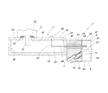
Referring to the drawings, an electrodeless, microwave lamp 1 has:
a magnetron 2, which is a conventional magnetron as used in a microwave oven,
provided
with a cooling a fan 21 and duct 22 and which operates at 2.45GHz;
an air waveguide matching circuit 3, in the form of a rectangular aluminium
trough 31
enclosing an air filled cavity 32, which is of rectangular cross-section
transverse to its length.
For inputting microwaves into the cavity, the output antenna 23 of the
magnetron extends
through an aperture 33 in a lid 34 closing the enclosure. A rim 35 of the
aperture 33 is in firm
ground contact with ground mesh 24 of the magnetron surrounding the antenna.
The internal
dimensions of the waveguide are:
Length 121.7mm
Width 72.9mm
Height 42.8mm.
6
CA 02760651 2016-11-28
Attorney Ref: 1089P004CA01
The length of the waveguide is one wave length ¨ of 2.45GHz microwave
radiation in air,
adjusted for the shape of the components. The output antenna 23 of the
magnetron is arranged at
1/4 from one end 36 of the waveguide;
a microwave conductor 4 forming an output from the air wave guide for
inputting
microwaves to an antenna connection 41 is attached by a screw 42 to the lid 34
at 1/42 from the
other end 37 of the waveguide. This position provides for maximum voltage to
be transmitted
on. The conductor has a resonator portion 43, the portion held by the screw,
and turns through a
right angle to an output portion 44 at half the height of the waveguide and
passes through an end
wall 37 of the trough 31. Thence it extends as the antenna connection per se
through an
aluminium crucible holder 45. This houses a ceramic insulator 46, giving the
connection with
the crucible holder a co-axial property;
a lucent crucible 5 in the form of a disc of quartz having:
Diameter 49mm
Length 21mm.
It has a central void 51 filled with excitable material and an offset bore 52
for receiving the
antenna end 47 of the conductor 4. This end, although integral with its
antenna connection
portion 41 and its output portion 44 within the trough, comprises an antenna
for inputting
microwave energy into the crucible;
a perforate Faraday cage 6 covers the exposed end 53 and the side 54 of the
crucible. The
cage comprises perforate sheet metal 61 and has an imperforate band 62 ,via
which it and the
crucible is fastened to the crucible holder 45 with screws 63;
a ceramic insert 7 for a starter extends obliquely into the crucible holder,
and supports an
electrode 71 which extends close to the end 47 of the conductor. It is
connected to a starter
circuit 72 adapted to apply pulsed high voltage, which starts the plasma
discharge when the
magnetron is driven at low power. A photodiode 73 is mounted in the holder at
a position to
detect light from the crucible, via an optic fibre 74;
a control circuit 8 is connected to the magnetron, to provide it with drive
current, to the
starter circuit to control it and to the photodiode. When the lamp is to be
switched on, low drive
current is applied to the magnetron and the starter is operated. Once the
photodiode detects light,
the starter is switched off and the power to the magnetron is increased. The
light source is then
operational.
7
CA 02760651 2016-11-28
Attorney Ref: 1089P004CA01
It will be noted particularly from its frequency characteristic shown in
Figure 3 that the
waveguide acts as a transmission line between the magnetron and the coaxial
connection to the
antenna and the lucent crucible.
The invention is not intended to be restricted to the details of the above
described
embodiment. In particular it is not restricted to operating at 2.45GHz. We
anticipate that it can
operate between an order of magnitude lower and an order of magnitude higher
than this
frequency, bearing in mind that the length of the cavity in terms of the
wavelength of
microwaves or electromagnetic waves for one wavelength is inversely
proportional to the
frequency. In particular we anticipate operating at 434MHz and lower and at
5.2GHz and higher
and at frequencies in between. At higher frequencies, the overall length can
be increased by
multiples of half lambda. Indeed this is possible at lower frequencies but
does result in extra
length of a component that is already getting long.
8