Note: Descriptions are shown in the official language in which they were submitted.
CA 02761244 2011-11-07
WO 2010/132290
PCT/US2010/033999
APPARATUS AND METHODS FOR PURGING CATHETER SYSTEMS
Field of Invention
This invention is associated with apparatus and methods for clearing catheter
systems
(e.g. IV lines) by creating controlled and consistent turbulent flushing
pressure and flow
within the system to purge the line of unwanted residue, and, in particular,
the invention is
associated with apparatus and methods for creating such turbulent flushing
pressure and flow
substantially independent of clinician technique.
Background and Related Art
It is well known in IV care art that turbulent "start-stop" or "push-pause"
flushing of
IV catheters, e.g. central venous catheters, has become an accepted method for
purging
matter from catheters and, thereby, preventing build-up of deposits of blood,
blood residue
and IV drugs within a catheter. Such build-up can cause partial or complete
blockage of the
fluid pathway in a catheter system, requiring expensive and potentially
dangerous methods
for purging the catheter or necessitating a total catheter exchange. Often,
such blockages lead
to interruptions in therapy (e.g. IV therapy) that may compromise patient
care. Further, build-
up of residue within a catheter can also increase infection risk by providing
a breeding
medium for microorganisms. For this reason, push-pause flushing is
traditionally, and more
or less universally, taught to healthcare workers.
Push-pause (or turbulent) flushing simply requires a clinician to alternately
increase
and decrease an associated infusion rate during flushing. However, efficiency
and success of
catheter purging using push-pause flushing is well known to be completely
dependent upon
individual awareness, compliance and technique and a successful purging
operation is often
incomplete and problematic. For this reason, many users may not use such
turbulent flushing
effectively while others, due to lack of knowledge or perception of value, may
not use it at
all.
Also, other than using turbulence for catheter clearance, syringes, pumps and
other
fluid forcing mechanisms associated with IV infusion are substantially
operated in a laminar
1
CA 02761244 2011-11-07
WO 2010/132290
PCT/US2010/033999
flow domain. When pulsatile flow is used, pressure and flow characteristics
are constrained
well below those turbulent and volumetric flow levels required for effective
catheter purging.
In the wide spectrum of syringe design, it is common to find art which
provides
periodic stops of various types and kinds for syringe plungers. Generally,
many such stops
are employed to aid in accurately measuring and dispensing a portion of a
syringe fill. Once
such stops are reached, it is common for the plunger to be released to thereby
permit
controlled and substantially laminar flow to the next stop. In other words,
such stops are
generally released without a calculated, intentional force to propel the
stopper with sufficient
force for catheter purging. Other stops are commonly used to limit a syringe
to a single use.
Generally, these stops are hard and cannot be reasonably overcome, as is
common in single-
use hypodermic syringes.
An example of a plunger stop for the purpose of limiting injection of fluid
from a
syringe is found in U.S. Pat. No. 4,642,102 issued Feb. 10, 1987 to Hirofumi
Ohmori
(Ohmori). Ohmori discloses stops which engage recesses in a plunger rod
associated with a
plunger to interrupt discharge from the syringe. After each stop, the plunger
rod is strictly
stopped such that no excessive force is able to drive the plunger rod further.
Similarly U.S.
Pat. No. 5,024,661 issued Jun. 18, 1991 to Harry Wender (Wender) discloses a
single use
syringe having recesses along a plunger rod.
U.S. Pat. No. 5,318,544 issued Jun. 7, 1994 to John Drypen, et al. discloses a
metering syringe having a plunger rod containing a plurality of stop surfaces.
The stop
surfaces are spaced apart to define a predetermined dose volume. Plunger rod
rotation
relieves each stop to permit further dispensing.
U.S. Pat, No. 5,059,181 issued Oct. 22, 1991 to Robert B. Agran (Agran) also
discloses a syringe assembly having recesses in a plunger rod which are used
to retard a
second rearward displacement of the plunger rod associated with a second use
of the syringe
assembly, In similar manner, U.S. Pat. No. 5,084,017 issued Jan. 28, 1992 to
John Maffetone
(Maffetone) discloses a single use syringe having a notched plunger rod. The
syringe of
CA 02761244 2011-11-07
WO 2010/132290
PCT/US2010/033999
Maffatone is taught to operate smoothly, but to dissemble itself at the
completion of a single
use cycle,
U.S, Pat. No. 5,280,030 issued Oct. 5, 1993 to Cesar G. Corsich, et al.
(Corsich)
discloses a hypodermic syringe having a blockable piston capable of preventing
recharge and
reuse under some conditions.
U.S. Pat, No, 5,328,476 issued Jul. 12, 1994 to James Bidwell (Bidwell)
discloses a
single-use hypodermic syringe apparatus. Rach.et grooves in an associated
plunger rod are
used as Jock members such that when plunger is fully inserted or reinserted
into a casing, the
plunger is prevented from being withdrawn relative to the casing.
U.S. Pat. No. 6,283,941 issued Sep. 4, 2001 to Joel Schoenfeld, et al.
(Schoenfeld)
discloses a rod-like syringe plunger having a plurality of bead-like rachet
teeth. Schoenfeld
also discloses a single use syringe. Of particular note is the statement, "It
is a further object of
the present invention to provide a single use syringe which has a smooth
mechanical
operation and a plunger retraction force less than the industry maximum
standard." Such
objectives are commonly held in the syringe art for manipulating syringe
plunger rods.
U.S, Pat. No. 5,891,052 issued Apr. 6, 1999 to Paul L. Simmons (Simmons)
teaches a
syringe plunger sabot and sabot lock disposed within a syringe body, the sabot
lock
mechanism being selectively moveable between a locked and unlocked position.
Thereby an
engagement is made to create a vacuum for extracting material into the syringe
body,
U.S. Pat. No. 6,488,651 issued Dec. 3,2002 to David Paul Morris et al.
(Morris)
discloses a mixing syringe having a plunger rod dasher which permits flow
within the barrel
for communicating material to be mixed with material in a more proximal
chamber. Other
cylindrical barriers provide within chamber defining spaces which are
selectively displaced
by movement of the plunger rod. Other than resistances of fluid dynamics and
friction (and
stiction), no other retarding forces are taught.
3
CA 02761244 2011-11-07
WO 2010/132290
PCT/US2010/033999
U.S, Pat. No. 6,579,269 B1 issued Jun, 17, 2003 to Gennady I. Kleyman (Kleman)
discloses a dose measuring syringe. A plunger rod, as taught in Kleyman, has
formations
which increase resistance to displacement of the plunger rod and to produce an
audible sound
corresponding to a predetermined volume for a measured dose. Even so, there
are no
teachings in Kleyman for providing momentary stops which produce a
predetenntined amount
of turbulent flow in a catheter.
U.S. Pat. No. 5,685,864 issued Nov. 11, 1997 to Laurence M. Shanley, etal.
(Shanley) discloses an aspiration syringe device which operates oppositely to
aspirate rather
than discharge into a connected site. A right angle stem of an associated
plunger is equipped
with spaced flanges. Interior of the syringe barrel is equipped with at least
one stop. When a
flange is contiguous with a stop, advancement of the plunger is prohibited.
Rotation of the
plunger permits further advancement.
U.S. Pat. No. 4,995,869 issued Feb. 16, 1991 to Martin McCarthy (McCarthy)
discloses a single-use hypodermic syringe. A syringe barrel according to
McCarthy has an
interior undulating surface over which a skirt rides rearward under direction
of a proximally
directed manual force. While it seems apparent that the undulations will cause
a pulsation in
flow while discharging fluids via a patient needle, it is clear that there are
no related
teachings for creating turbulent flow in a catheter, a subject untouched in
McCarthy.
Generally, in summary, prior art, of which art cited above is an example,
discloses
and teaches plunger rod having slots, grooves and 'whet teeth are for
providing obstructions
used for measuring predetet wined volumes of dispensed fluids or for stops
associated with
providing single use syringes. just as clinician-dependent generation of push-
pause flow is
problematic, all such art is void of teachings which assure successful
creation of turbulent
flow for clearing an associated attached catheter system. Such is the specific
and precise
purpose of the present invention.
BRIEF SUMMARY AND OBJECTS OF THE INVENTION
In brief summary, this novel invention alleviates all of the known problems
related to
generating controlled and predetermined push-pause pressures and flows thereby
providing
4
CA 02761244 2011-11-07
WO 2010/132290
PCT/US2010/033999
controlled and consistent turbulent flow which is effective in purging matter
disposed within
a catheter system, The invention comprises methods and apparatus which are
defined and
designed to produce pressures resulting from dynamic releases by predetermined
forces, each
for a period which provides a controlled and consistent surge to effectively
produce turbulent
purging fluid flow at a site of concern within a catheter system.
Generally, such flow is provided to a catheter system from a source of flush
liquid
from a container sized to hold a volume of liquid consistent with flow volume
requirements
of a desired pressure pulse. In each case, an actuator opens a valve mechanism
at a
___ predetel bined pressure to initiate the desired liquid pulse pressure
and resulting liquid flow.
The sensing actuator has an operating hysteresis which ultimately stops flow
to end the
pressure pulse. Of course, an implement which, by example, may be a pump or
piston, is a
crucial part of the apparatus for providing sufficient pressure to activate
the valve
mechanism. To retain adequate pressure throughout the pulse, a memory element
provides a
source of stored energy received from the implement and releases the stored
energy upon
valve mechanism opening to retain the turbulent flushing -fluid pressure and
flow for a desired
pulse period.
One embodiment of the apparatus is application of the invention to a syringe,
and
more specifically, to a plunger rod of a syringe. In such a case, the barrel
of a syringe is the
container. Displacement of the plunger rod (and associated plunger) within the
barrel acts as
an implement to dispense liquid from the syringe. Commonly found at the
proximal end of
conventional syringes is a retention ring formed of reduced diameter relative
to the diameter
of the rest of the syringe barrel. This retention ring is used as a tactile
indicator between an
entry disk disposed on the stern of a plunger rod just proximal from the
plunger affixed to the
plunger rod, providing an impedance which must be overcome to extract the
plunger rod (and
plunger) from the syringe barrel.
At least one actuating geometry, sized and shaped to require a predetermined
force to
displace the actuating geometry past the retention ring, is disposed
proximally on the stem
relative to the entry disk. Forcing the actuating geometry past the retention
ring yields the
force necessary to provide desired turbulent flushing fluid pressure and
initiate flow. Such
5
CA 02761244 2011-11-07
WO 2010/132290
PCT/US2010/033999
geometry may be a disk on the plunger or an interfacing nub on exterior edges
of shafts of a
plunger rod, Reflexive motion associated with forcing the actuating disk past
the retention
disk provides the memory based, stored energy necessary to assure continuation
of forced
flow thereby providing the pressure pulse. The length of the pressure pulse is
determined by
either the plunger being displaced to empty the syringe barrel or a second
actuating disk
disposed proximally on the stem relative to the actuating disk just forced
through the
retention ring to provide a tactilely determinable stop. Note, that resistance
of this stop,
relative to reflexive energy applied to displace the syringe plunger rod,
provides the
hysteresis specified. In this manner, a conventional syringe barrel, in
combination with a
plunger rod made according to specifications of the instant invention, can
provide desired
pulse-pause pressure pulses from a syringe substantially independent of a
syringe user. It may
be preferred to provide a segment of a plunger rod free of actuating geometry
to provide a
"no-pulse" segment to enable conventional flush technique to check for
possible occlusions
and to verify blood return.
In another embodiment, the pulse-pause pressure pulse is provided by an in-
line
apparatus. Source for fluid is from a receptacle having sufficient volume to
fill a container
from which the pressure pulse is generated, the container being a hollow
cylindrical vessel
which receives liquid from the receptacle through a one-way valve.
Communication for
dispensing liquid to the catheter system is through another one-way valve.
The valve mechanism is a plunger, sized and shaped to displace fluid within
the
vessel through the one-way valve to the catheter system. Further, the vessel
has a retention
ring similar to the retention ring of the barrel of a conventional syringe. A
valve-actuating
disk associated with the plunger is sized and shaped to require predetermined
force necessary
to generate a desired pulse toward the catheter system. Volume of the vessel
determines pulse
volume. Again, as in the case of the syringe, reflexive action resulting from
release of force
when the actuating disk is driven past the retention ring assures adequate
pulse pressure. The
actual implement for driving the plunger is derived from a button affixed to
the plunger and
associated rod whereby the plunger is manually driven through the vessel. A
spring disposed
6
CA 02761244 2011-11-07
WO 2010/132290
PCT/US2010/033999
to be compressed when the pressure pulse is generated stores energy to return
the plunger and
refill the vessel for a subsequent pulse-pause cycle.
Other embodiments of the present invention involve a pressure sensitive switch
having an actuator which opens the valve at a higher predetermined pressure
and closes at a
lower predetermined pressure. Generally, the source is a fluid receptacle
upstream from a
pressure-providing device which provides fluid dispensed at a predetermined
pressure and
flow. A vessel acts as a container which communicates with the pressure
providing device
through a flow restrictor. Further, the vessel communicates with the catheter
system through
the pressure sensitive valve. The pressure sensitive valve is selected to have
an opening
pressure which provides a fluid pulse having desired turbulent flow
characteristics and
closing at a pressure after a desire flow volume has been achieved and
pressure within the
vessel is reduced below the lower predetermined pressure.
In one of these other embodiments, a pump provides pressure of the source. A
spring
loaded piston chamber provides opportunity to gather volume for the pressure
pulse which
fills at a pressure lower than the higher predetermined pressure through a
flow restrictor
affixed to the output of the pump, but at a pressure higher than the lower
predetermined
pressure. Thus, the higher predetermined pressure is reached only upon filling
the chamber,
Once the chamber is filled, the valve is opened by the actuator to initiate
the controlled
pressure pulse. When the chamber is emptied, pressure in the vessel drops
below the lower
predetermined pressure and the actuator closes the valve. If this embodiment
remains affixed
to the catheter system a subsequent pressure pulse is generated automatically.
Another of other embodiments involves a squeezable tube. In this case the tube
communicates with the catheter system through a pressure sensitive valve,
having valve
actuator opening characteristics as disclosed supra. Upstream the tube
communicates with the
source through a one-way valve. Pressure from the source does not reach or
exceed the higher
predetermined pressure, but is sufficient to fill the tube. Thus, pressure
from the upstream
source and elastic memory in the tube cause the tube to fill through the
upstream one-way
valve. Once the tube is adequately filled, it is selectively squeezed to cause
the pressure to
rise to at least the higher predetermined pressure. Once pressure within the
tube is at or above
7
CA 02761244 2011-11-07
WO 2010/132290
PCT/US2010/033999
the higher predetermined pressure, the valve is opened and the pressure pulse
is initiated. The
pressure pulse is continued by reflexive action following valve opening.
Expulsion of liquid
from the tube ultimately results in valve closing ending the pressure pulse.
The pressure pulse
may be continued until the tube is substantially empty.
Methods for using embodiments of the instant invention generally involve
filling a
chamber or vessel, of predetermined size, from which a pulse of liquid is to
be dispensed,
causing pressure within the chamber or vessel to exceed a predetermined
pressure and
selectively opening a pathway to the catheter system only when that pressure
is achieved. In
that manner, a desired, controlled pulse-pause pressure pulse is achieved and
provided
substantially independent of performance of a user.
Accordingly, it is a primary object to provide apparatus which provides
substantially
user independent, controlled pulse-pause pulsatile flow of sufficiently
turbulent flushing
pressure and flow within a catheter system to substantially purge the line of
unwanted
residue.
It is a primary object to provide such apparatus which is used within a barrel
of a
conventional syringe.
.7)0
It is another primary object to provide such apparatus which provides in-line
operation between a fluid source and the catheter system.
It is an object to provide such apparatus which provides for a series of
manually
generated pulse-pause pressure pulses.
It is an important object to provide such apparatus which uses a pump as an
implement.
It is another object to provide apparatus which provide controlled pressure
pulses
resulting from opening and closing a pressure sensitive valve.
8
CA 02761244 2011-11-07
WO 2010/132290
PCT/US2010/033999
These and other objects and features of the present invention will be apparent
from
the detailed description taken with reference to accompanying drawings.
Definitions of Some Tern-is Used in the Specification
catheter system\n: a combination of tubes and other devices used to deliver
fluids to
patients, e.g. a medical catheter (e.g. IV catheter), delivery tubing (e.g.
feeding tube) and
associated connectors
fluid\n: a gas or liquid
IV\adj: a mode of delivery of fluids to a patient, in this case the mode is
Intravascular
laminar flow\n: streamline flow which is relatively smooth and even, such as
flow near a
solid boundary and contrasted with turbulent flow
turbulent flow\n: a fluid flow in which the velocity at a given point varies
erratically in
magnitude and direction with time and is thus essentially variable in pattern
and is contrasted
with laminar flow
valve mechauism\n a fluid control device generally defined herein to be a
device for
initiating a pressure pulse when opened and ending the pressure pulse when
closed; within
this general definition, pulse-pressure generating action of a syringe plunger
rod being
displaced to actuate a pressure pulse is considered to be a valve mechanism
BRIEF DESCRIPTION OF THE DRAWINGS
FIG. 1 is a perspective of a syringe and plunger rod made according to the
present
invention where stern of the plunger rod has a plurality of disks disposed
upon the length
thereof.
FIG. 2 is a cross section of the syringe and plunger rod and seen in FIG. 1.
FIG. 2A is a cross section of a syringe and plunger rod which is similar to
the syringe
and plunger rod of FIG. 2, but wherein edges of disks are shaped to facilitate
displacing the
plunger rod into the syringe and deterring the plunger rod from being removed
from the
barrel, once so displaced.
9
CA 02761244 2011-11-07
WO 2010/132290
PCT/US2010/033999
FIG, 2B is a cross section of a syringe and plunger rod which is similar to
the syringe
and plunger rod of FIG. 2, but wherein edges of disks are shaped to facilitate
displacing the
plunger rod out of the syringe once displaced therein.
FIG. 2C is a cross section of a syringe and plunger rod which is similar to
syringes
and plunger rods of FIGS. 2, 2A and 2B, but having nubs along a shaft of a
plunger rod
instead of disks.
FIG. 3 is a perspective of the plunger rod seen in FIG. 1.
FIG. 4 is a perspective of a syringe and plunger rod wherein the plunger rod
is similar
to the plunger rod of FIG. I but fabricated with a plurality of breakaway
rings disposed about
to stem of the plunger rod,
FIG. 5 is a perspective of the plunger rod seen in FIG. 4.
FIG, 6 is a perspective of the syringe and plunger rod seen in FIG. 4 with at
least one
breakaway ring sheered from the stem of the plunger rod,
FIG. 7 is a perspective of a syringe and plunger rod wherein the plunger rod
is similar
to the plunger rod of FIG. I but having a pattern of undulations on the stem
and a
constraining elastomeric ring about the proximal syringe barrel opening.
FIG. 8 is a cross section of the syringe, plunger rod and elastomeric ring
seen in FIG.
7.
FIG. 9 is a perspective of an automatic, in-line pulsing device made according
to the
present invention.
FIG. 10 is a cross section of the automatic, in-line pulsing device seen in
'FIG. 9
showing state of the device at the end of a pulse.
CA 02761244 2011-11-07
WO 2010/132290
PCT/US2010/033999
FIG. 11 is a cross section of the automatic pulsing device seen in FIG. 9
showing state
of the device when charged before actuating a pulse.
FIG. 12 is a cross section of the automatic pulsing device seen in FIG. 9
showing state
of the device during pulse generation.
FIG. 13 is a perspective of the device seen in FIG. 9 with a syTinge affixed
to the
device to provide a fluid pressure source.
FIG. 14 is a schematic drawing of a system which employs a pumped fluid source
for
the device seen in FIG. 9.
FIG. 15 is a perspective of a squeezable device for providing a controlled
pressure
pulse according to the instant invention.
FIG. 16 is a cross section of the device seen in FIG. 15.
FIG. 17 is a cross section of the device seen in FIG. 14 with a medical
section
squeezed at the end of a controlled release pressure pulse.
FIG. 18 is a perspective of a manually operated controlled pressure pulse
device made
according to the present invention.
FIG. 19 is a cross section of the device seen in FIG. 18 filled before
initiating a
controlled pressure pulse.
FIG. 20 is a cross section of the device seen in FIG. 18 at the end of a
pressure pulse.
DETAILED DESCRIPTION OF THE ILLUSTRATED EMBODIMENTS
In this description, the term proximal is used to indicate the segment of the
device
normally closest to the object of the sentence describing its position. The
term distal refers to
11
CA 02761244 2011-11-07
WO 2010/132290
PCT/US2010/033999
a site opposite the proximal section. Reference is now made to the embodiments
illustrated in
FIGS. 1-20 wherein like numerals are used to designate like parts throughout.
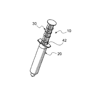
Reference is now made to FIG. I wherein a preferred embodiment of a
syringe/plunger rod combination 10 of the instant invention is seen.
Combination 10
comprises a conventional syringe barrel 20 and a plunger rod 30. Salient
features of
combination 10 are better seen in FIG. 2 to comprise barrel 20 having a
retention ring 40
disposed at proximal barrel hole opening 42 and plunger rod 30 comprising a
plurality of
actuating geometry, interfaces or rings, generally numbered 50) disposed along
a stem 60
thereof. In addition, as is common with plunger rods of conventional syringes,
plunger rod 30
has a plunger 70 affixed to the distal end 80 of stem 60. It may be noted that
distal end 80 has
a threaded geometry portion 90 which permits plunger rod 30 to be affixed to
plunger 70 after
barrel 20 is tilled with liquid, generally referenced as liquid 72. A plunger
rod 30 is seen
alone in FIG. 3 providing a clearer view of threaded portion 90.
Further, plunger rod 30 has a first ring 92 which can be forced past retention
ring 40
when plunger 70 and stem 60 are inserted into barrel 20. First ring 92 is
sized and shaped to
be forcible displaced through retention ring 40, but provide a tactilely
discernable stop such
that plunger 70 is not inadvertently displaced out of barrel 20.
Each actuator ring 50 is sized and shaped to be obstructed by retention ring
40. Each
actuator ring 50 is further sized and shaped to require a predetermined force
which must be
exceeded to displace a contacting actuator geometry (e.g. retention ring
interface 50) past
retention ring 40. For this reason, fluid within barrel 20 is displaced with
resulting
acceleration and velocity resulting from the predetermined force when the
contacting ring 50
is releasibly displaced through retention ring 40. Generally the resulting
acceleration and
velocity is of liquid which is discharged from syringe barrel 20 to
turbulently flush liquid 72
through an associated catheter system. In this manner, each time a contacting
ring 50 is
displaced past retention ring 40 a pulse of pressurized liquid 72 is purged
into the catheter
system providing a turbulent flushing pulse of liquid 72 there through.
IL
CA 02761244 2011-11-07
WO 2010/132290
PCT/US2010/033999
As well, a more proximal ring 94 of rings 50 may be further shaped and sized
to
require a force which is greater than more distal rings 50 to provide a
reminder that the pulse
resulting from actuation using ring 94 is the last pulse provided by liquid 72
from
combination 10. For this reason, ring 94 may be referenced as reminder ring 94
hereafter.
Note, that, if plunger rod 30 is not displaced sufficiently far into barrel 20
to displace
reminder ring 94 past retention ring 40, no back flow or reflux should occur
in an associated
catheter system. Note that proximal end 98 of stem 60 is convex or dome shaped
to facilitate
application of digital force against plunger rod 30.
As well, it may be noted that rings 50 are not necessarily spaced uniformly.
As an
example a space 99 between first ring 92 and next most proximal ring 50 is
relatively large
compared to space between other rings, generally numbered 50. This provides
for a ''no-
pulse" segment which may be used for conventional sampling for catheter blood
flow to
assure proper catheter operation.
Attention is now directed to FIG. 2A wherein a second combination 20' of a
conventional syringe barrel 20 and a plunger rod 30' is seen. Plunger rod 30
is similar to
plunger rod 30, having a series of actuator rings 50' disposed along the
length thereof.
However, in the case of combination 10, rings 50' are shaped and sized (as
seen in FIG. 2A)
to be more easily displaced into barrel 20 (and distally through retention
ring 40) than
displaced barrel 20 (proximally through retention ring). Such meets a
condition whereby
plunger rod 30' is not easily removed from barrel 20, once used to promote a
single use
application.
75 On the other hand, it may be desired to refill and reuse such a
combination. In such a
case, it is desired to displace a plunger rod 30" of a third combination 10"
more easily
proximally than distally. In such a case, actuating rings 50" disposed along a
stem 60 are
shaped as seen in FIG. 2B.
Rings 50 seen in FIG. 2, may be replaced by nubs 52 on a plunger rod 32 as
seen as
combination 12 in FIG. 2C. Replacement of rings 50 by nubs 52 may be done
without
13
CA 02761244 2011-11-07
WO 2010/132290
PCT/US2010/033999
degradation of effect of producing desired turbulence by sizing and shaping
nubs 52 to
require forces similar to that required of rings 50 for displacement past
retention ring 40.
Another embodiment, seen as combination 110, of the instant invention is seen
in
FIGS. 4-6. As in combination 10, combination 110 comprises a conventional
syringe barrel
20. Note that syringe barrel 20 has a proximal entry hole 122 associated with
retention ring
40. As seen in FIGS. 4 and 5, an associated plunger rod 30 also comprises a
series of actuator
rings, generally numbered 150. disposed along a stem 60 of plunger rod 130.
However, rather
than being sized and shaped to be forced through retention ring 40 of barrel
20 to create a
desired pressure pulse, rings 150 are affixed to stem 60 in a manner which
permits each
actuation ring 150 to be sheared from stern 60 as it is displaced into barrel
entry hole 42.
Shear force at separate actuation rings 150 from stem 60, similar to
displacement
force past retention ring 40 of combination 10, is geometrically and
mechanically designed to
provide a predeteimined acceleration and velocity which purveys desired
turbulent flow to
purge and discharge unwanted contaminants from a downstream catheter system.
Note, in
FIG. 6, that a first more distally disposed actuator ring 150 is seen to be
captured by a second,
more proximally disposed actuator ring 150 exterior to hole in FIG. 6. Note
that piling up of
sheared actuation rings 150 may be used to prevent a syringe from being fully
evacuated.
Yet another embodiment of the instant invention is seen as combination 210,
which
may use a conventional syringe barrel 20, is seen in FIGS_ 7 and 8. In
addition to barrel 20,
combination 210 comprises an elastomerie restrictor 230 a plunger rod 240 with
a stem 242_
Stern 242 comprises a plurality of elongated side members, each numbered 244.
Each side
25 member has an undulating exterior edge, numbered 246. High points of the
undulations are
generally numbered 248.
Restrictor 230 is shaped and configured to provide a port about barrel entry
hole 42
(see FIGS. 1 and 2). A restrictor entry hole 250 is sized and shaped to
obstruct inward
30 displacement of plunger rod 240 upon collision between restrictor 230
and each high point
248. A combination of selected durometer of the elastomer of restrictor 230,
and collision
geometry of high points 248 and hole 250 combine to require a predetermined
force for
14
CA 02761244 2011-11-07
WO 2010/132290
PCT/US2010/033999
further displacement of plunger rod 240. This predetermined force is
comparable to the force
required for displacement of plunger rod 30 past retention ring 40 (see FIGS.
1-3), In this
manner, a pressure pulse which provides turbulent flow for purging an attached
catheter
system is generated each time high points 248 are displaced through hole 250
of restrictor
230.
Reference is now made to FIGS. 9-12 wherein an in-line automatic pulsing
device
310 m.acie according to the instant invention is seen. As seen in FIG. 9,
device 310 comprises
an upstream or proximal connection 320, into which liquid from a liquid source
is provided.
Further device 310 comprises an output port and connector 330 which may be
connected to a
downstream catheter system. For proper operation, liquid pressure available
from the source
must be greater than desired pressure of a purging liquid pulse emitted by
device 310.
As seen in FIG. 10, a pressure sensitive valve 340 is disposed to close output
port and
connector 330 when pressure is below the desired pressure. Just distal from
proximal
connection 320 is a check valve 350 to obstruct backflow and retard inflow to
a
predetermined level of flow. Medially disposed between pressure sensitive
valve 340 and
check valve 350 is a pulse reservoir chamber 360. Disposed within chamber 360
is a piston
370 and spring 380 which acts within chamber 360 to store a volume of liquid
when valve
330 is closed.
When choosing pressure sensitive valve 340, a valve should be selected which
has an
opening pressure to closing pressure hysteresis having a predetermined
pressure differential
for purposes clarified hereafter. The pressure differential being defined as a
difference
between release high pressure and a low closing pressure. The high pressure
being a pressure
which creates a pressure pulse having sufficient force and flow to cause down
stream
turbulence which purges a desired amount of material from an attached catheter
system. The
lower pressure being a pressure to which pressure inside device 310 falls
after clearing of
Liquid from chamber 360. Note that, for pressure inside 310 to fall to the
lower pressure,
inflow from the source must be restricted to a lower flow rate than outflow
through output
owl and connector 330,
CA 02761244 2011-11-07
WO 2010/132290
PCT/US2010/033999
Steps of operation of device 310 are seen to embody a beginning state seen in
FIG. 10
where chamber 360 is empty and spring 380 is decompressed and valve 350 is
closed.
Subsequent filling of chamber 360 is seen in FIG. 11. Valve 340 is opened when
spring 380
is fully compressed to discharge liquid from device 310 thereby. Of course,
once valve 350
closes, the pulse cycle repeats.
Sources for pressurized fluid for device 310 are seen in FIGS. 13 and 14. In
FIG. 13, a
conventional syringe 390 is affixed to proximal connection 320. Source
pressure is provided
by the force displacing an associated plunger rod 392. Note that sufficient
pressure is
required to fully charge chamber 360 before actuating valve 350.
In FIG. 14, a more sophisticated pressure providing source system is seen
including a
saline bag 304, a pump 396 and a variable liquid flow restrictor 398. Source
liquid from bag
394 is drawn and pumped by pump 396 to provide pressure equal to or greater
than the high
pressure necessary to open valve 350. Variable restrictor is set to determine
pump 396 to
device 310 liquid transfer rate to determine device 310 output pulse rate.
Reference is now made to FIGS. 15-17 wherein an in-line pinch or squeeze pump
410, made according to the instant invention, is seen. As seen in FIG. 16,
device 410
comprises an upstream or proximal connection 420, into which liquid from a
liquid source is
provided. Further device 410 comprises an output port and connector 430 which
may be
connected to a downstream catheter system. For proper operation, liquid
pressure available
from the source must only be greater than filling pressure of an expandable
tube 440 which is
sized and shaped to be easily filled and purged by squeezing.
As seen in FIG. 16, a pressure sensitive valve 340 (see also FIGS. 11-13 of
device
310, disclosed supra) is disposed to close output port and connector 430 when
pressure is
below a predetennined pressure. Just distal from proximal connection 420 is a
check valve
450 to obstruct backtlow. Tube 440 provides a storage medium which defines
pulse flow
quantity when device 410 is actuated. To operate, tube 440 is squeezed until
valve 340 is
opened to provide a pressure pulse according to the present invention.
Continued reflexive
squeezing dispenses liquid through valve 340 to create a plusatile flow of
liquid having
16
CA 02761244 2011-11-07
WO 2010/132290
PCT/US2010/033999
sufficient turbulent flow and pressure to purge an attached catheter system.
Note that pressure
of source liquid need only be at a sufficiently high pressure to fill tube 440
and that tube 440
may have sufficient inherent structural memory to provide a somewhat negative
filling
pressure requirement. This same memory reduces liquid pressure inside tube 440
to cause
valve 340 to close at the end of a pulse generating cycle.
Another device 510 which provides manually, digitally generated controlled
pressure
pulses for purging catheter systems according to the present invention is seen
in FIGS. 18-20.
As seen in FIG. 19, device 510 comprises an upstream or proximal connection
520, into
which liquid from a liquid source is provided. Further device 510 comprises an
output port
and connector 530 which may be connected to a downstream catheter system. For
proper
operation, liquid pressure available from the source must only be greater than
filling pressure
of a spring piston combination 540. Combination 540 comprises a depressible
button and rod
550, a compressible spring 560 and a plunger 570. Plunger 570 is sized and
shaped to
evacuate liquid from a hollow vertical chamber 580 which communicates
orthogonally with a
hollow liquid flow chamber 590 disposed for liquid communication between
proximal
connection 520 and output port 530. Amount of liquid stored in vertical
chamber 580 and
released upon displacement of plunger 570 determines pulse volume of liquid
delivered to the
downstream catheter system.
As seen in FIG. 19, a pressure sensitive valve 340 (see also FIGS. 11-13 of
device
310, disclosed supra) is disposed to close output port and connector 530 when
pressure is
below a predetermined pressure. Just distal from proximal connection 520 is a
check valve
450 to obstruct backflow. To operate device 510, button 550 is depressed to
open valve 340
thereby providing a pressure pulse according to the present invention.
Continued reflexively
depressing button 550 dispenses liquid through valve 340 to create a plusatile
flow of liquid
having sufficient turbulent flow and pressure to purge an attached catheter
system. Note that
pressure of source liquid need only be at a sufficiently high pressure to fill
chamber 580 and
that combination 540 with spring 560 should have sufficient inherent
structural memory to
provide a negative filling pressure inside chamber 590. This same memory
reduces liquid
pressure inside chamber 590 to cause valve 340 to close at the end of a pulse
generating
cycle.
17
CA 02761244 2016-08-16
To operate device 510, chamber 580 is permitted to fill with liquid provided
through
connector 520. Button 550 is depressed to provide sufficient force to open
valve 340 and
reflexively thereafter continued to be depressed until liquid is purged from
chamber 580 as
seen in FIG. 20 to produce the desired purging pressure pulse. Once
combination 540 is fully
depressed, force on button 550 is relieved to permit refilling of chamber 580
for generating a
subsequent pressure pulse.
The invention may be embodied in other specific forms. The present embodiment
is therefore to be considered in all respects as illustrative and not
restrictive. The scope of
the claims should not be limited to the illustrative embodiments, but should
be given the
broadest interpretation consistent with the description as a whole.
18