Note: Descriptions are shown in the official language in which they were submitted.
CA 02761319 2011-11-07
WO 2010/129743 PCT/US2010/033830
SYSTEMS AND METHODS FOR REDUCING MERCURY EMISSION
CROSS-REFERENCE TO RELATED APPLICATIONS
[0001] This application claims the benefit of priority to U. S. Provisional
Application No.
61/176,564, filed on May 8, 2009, which is incorporated by reference herein in
its entirety.
BACKGROUND
[0002] When a material containing mercury is combusted, for example during an
industrial combustion process, the mercury is volatilized and often emits into
the
atmosphere. Recent estimates suggest that United States power plants alone
emit about 50
tons of mercury per year into the atmosphere. Various forms of volatilized
mercury can
form during combustion processes. Volatilized elemental mercury, Hg , and
oxidized
mercury are typically present in flue produced from the combustion of a
material
containing mercury. Elemental mercury vapor has an atmospheric lifespan of
several years
and will travel the globe before finally oxidizing in the atmosphere and
depositing onto
land and in water. Oxidized mercury, by contrast, has a relatively short
atmospheric
lifespan and will condense along with rain into bodies of water or can deposit
onto plants
and subsequently wash into bodies of water.
[0003] Once the mercury finally deposits into water and settles into the biota
of shallow
lakes and oceans, sulfur-reducing microorganisms can convert the mercury to a
very toxic
and bioaccumulative organic form of mercury, methyl mercury. Methyl mercury
tends to
accumulate in fish and can accumulate in the humans that eat fish, potentially
leading to a
variety of health problems, including learning disabilities, cardiovascular
diseases,
autoimmune disorders, and can lead to development problems in feti. The
toxicity of
methyl mercury is linked to a variety of factors, including its high
reactivity and long half-
lives in living organisms, which can be as high as 72 days in fish and 50 days
in humans.
Regulations on mercury to date have focused on total vapor-phase mercury
emissions
from stacks (regardless of form) and the total concentration of mercury in
waste-water
discharge.
[0004] Various methods exist for mitigating mercury emission from the flue gas
of an
industrial process. Often, these methods involve first oxidizing the mercury
to form HgC12,
since elemental mercury is not easily captured from flue gas. Traditional
pollution control
devices, such as wet scrubbers and selective catalytic reduction (SCR) units,
which are
1
CA 02761319 2011-11-07
WO 2010/129743 PCT/US2010/033830
designed to capture SO2 and destroy NO before they exit flue-gas stacks, also
help to
oxidize and capture mercury. Oxidized mercury, however, even if captured, can
at least
partially re-emit from the pollution control devices back into the flue gas
and emit from
the stack.
[0005] Other methods for mitigating mercury emission from flue gas involve the
use of
additives. One method for reducing mercury emission from a coal combustion
power
plant, for example, involves placing a bromide salt directly on coal prior to
combustion.
The bromide salt is then volatilized at high temperatures to form more potent
oxidants as
the coal is burned in the furnace. However, the addition of bromide salts
directly onto the
coal can cause boiler-tube wastage and corrosion of other component surfaces
in the
furnace, convection pass, and ductwork prior to reaching the location in the
flue gas where
it is needed to oxidize mercury. In addition, some of the desirable bromine
gas may be
consumed in side reactions before arriving at the point where the bromine gas
is needed to
oxidize mercury.
[0006] Accordingly, there exists a need for improved methods for reducing
mercury
emission that results from an industrial process. This need and other needs
are satisfied by
the present invention.
SUMMARY
[0007] Described herein are methods for reducing mercury emission from a flue
gas.
Generally, the methods involve providing a relatively inert halide salt,
converting the
halide salt to an acid halide, and converting the acid halide to a molecular
halogen that can
be injected into a process stream. The mercury in the flue gas is then
oxidized by the
molecular halogen and removed from the process stream, thus preventing the
emission of
the mercury into the atmosphere. Also described are systems for carrying out
the disclosed
methods. Also described are improved methods for making bromine, wherein
hydrobromic acid is formed from a bromide salt, and the hydrobromic acid is
subsequently
oxidized to bromine.
[0008] The advantages of the invention will be set forth in part in the
description which
follows, and in part will be obvious from the description, or may be learned
by practice of
the aspects described below. The advantages described below will be realized
and
attained by means of the elements and combinations particularly pointed out in
the
appended claims. It is to be understood that both the foregoing general
description and the
following detailed description are exemplary and explanatory only and are not
restrictive.
2
CA 02761319 2011-11-07
WO 2010/129743 PCT/US2010/033830
BRIEF DESCRIPTION OF THE DRAWINGS
[0009] Fig. 1 is a graph of the % conversion of CaBr2 to Br2 under the process
conditions
described in Example 1.
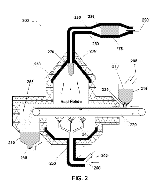
[0010] Fig. 2 is an example of a disclosed system.
[0011] Fig. 3 is another example of a disclosed system.
DETAILED DESCRIPTION
[0012] Before the present compounds, compositions, composites, articles,
devices,
methods, or uses are disclosed and described, it is to be understood that the
aspects
described below are not limited to specific compounds, compositions,
composites, articles,
devices, methods, or uses as such may, of course, vary. It is also to be
understood that the
terminology used herein is for the purpose of describing particular aspects
only and is not
intended to be limiting.
[0013] In this specification and in the claims that follow, reference will be
made to a
number of terms that shall be defined to have the following meanings:
[0014] Throughout this specification, unless the context requires otherwise,
the word
"comprise," or variations such as "comprises" or "comprising," will be
understood to
imply the inclusion of a stated integer or step or group of integers or steps
but not the
exclusion of any other integer or step or group of integers or steps.
[0015] It must be noted that, as used in the specification and the appended
claims, the
singular forms "a," "an" and "the" include plural referents unless the context
clearly
dictates otherwise. Thus, for example, reference to "a molecular halogen"
includes
mixtures of two or more such molecular halogens, and the like.
[0016] "Optional" or "optionally" means that the subsequently described event
or
circumstance can or cannot occur, and that the description includes instances
where the
event or circumstance occurs and instances where it does not.
[0017] Ranges may be expressed herein as from "about" one particular value,
and/or to
"about" another particular value. When such a range is expressed, another
aspect includes
from the one particular value and/or to the other particular value. Similarly,
when values
are expressed as approximations, by use of the antecedent "about," it will be
understood
that the particular value forms another aspect. It will be further understood
that the
endpoints of each of the ranges are significant both in relation to the other
endpoint, and
independently of the other endpoint.
3
CA 02761319 2011-11-07
WO 2010/129743 PCT/US2010/033830
[0018] Disclosed are compounds, compositions, and components that can be used
for, can
be used in conjunction with, can be used in preparation for, or are products
of the
disclosed methods and compositions. These and other materials are disclosed
herein, and
it is understood that when combinations, subsets, interactions, groups, etc.
of these
materials are disclosed that while specific reference of each various
individual and
collective combinations and permutation of these compounds may not be
explicitly
disclosed, each is specifically contemplated and described herein. For
example, if a
number of different polymers and agents are disclosed and discussed, each and
every
combination and permutation of the polymer and agent are specifically
contemplated
unless specifically indicated to the contrary. Thus, if a class of molecules
A, B, and C are
disclosed as well as a class of molecules D, E, and F and an example of a
combination
molecule, A-D is disclosed, then even if each is not individually recited,
each is
individually and collectively contemplated. Thus, in this example, each of the
combinations A-E, A-F, B-D, B-E, B-F, C-D, C-E, and C-F are specifically
contemplated
and should be considered disclosed from disclosure of A, B, and C; D, E, and
F; and the
example combination A-D. Likewise, any subset or combination of these is also
specifically contemplated and disclosed. Thus, for example, the sub-group of A-
E, B-F,
and C-E are specifically contemplated and should be considered disclosed from
disclosure
of A, B, and C; D, E, and F; and the example combination A-D. This concept
applies to
all aspects of this disclosure including, but not limited to, steps in methods
of making and
using the disclosed compositions. Thus, if there are a variety of additional
steps that can
be performed it is understood that each of these additional steps can be
performed with
any specific aspect or combination of aspects of the disclosed methods, and
that each such
combination is specifically contemplated and should be considered disclosed.
[0019] As used herein, "injecting" refers to a step wherein a molecular
halogen is added to
a flue gas. Typically, injecting the molecular halogen involves introducing
the molecular
halogen into the flue gas from a source that is separate from the flue gas
itself, e. g. from
an injection system.
[0020] As used herein, a "flue gas" refers to an exhaust gas that is produced
from an
industrial process and includes both gas that will be used in connection with
the process
from which it is produced or even another related process (e. g. , to produce
heat) and gas
that is waste gas, which will exit into the atmosphere via a duct for
conveying waste
exhaust gases from an industrial process. The flue gas can be produced from
any industrial
process, wherein any form of mercury is present in the flue gas. Examples of
such
4
CA 02761319 2011-11-07
WO 2010/129743 PCT/US2010/033830
industrial processes include power generating processes, (e. g. , combustion
processes),
metal smelting processes (e. g. gold smelting), chlor alkali production
processes, among
others.
[0021] As used herein, a "molecular halogen" is any halogen in molecular form
(i. e. a
species comprising more than one atom), or a product dissociated therefrom.
Examples of
molecular halogens include without limitation Br2, Cl2, F2, and 12. Products
dissociated
from the molecular halogen include those products that form from the molecular
halogen
when the molecular halogen is injected into flue gas, such as ions or other
products
resulting from the disassociation of the molecular halogen. For example, Br2,
at certain
flue gas conditions, may become dissociated to form a Br radical, Br anion, Br
cation, or a
combination thereof. Such disassociation products will typically be very
reactive.
[0022] A "halide salt," as used herein, is any salt of a halide (X-', wherein
X is Br, Cl, F,
or I). The cationic portion of the halide salt can be any suitable cation,
including without
limitation cations of Group I and II elements, such as Li, Na, K, Ca, or Mg,
and certain
cations of transition metal elements, such as Group VIII elements, including
for example,
Fen+, wherein n is 1, 2 or 3.
[0023] "Mercury," as used herein, refers to any form of mercury, including
without
limitation, all oxidized forms of Hg and molecular Hg.
[0024] The present invention provides systems and methods wherein relatively
inert
halide salts are transformed to molecular halogens and subsequently can be
directly
injected at the point of need in an industrial process to oxidize mercury and
subsequently
reduce mercury emission from the process stream. According to the methods
disclosed
herein, inexpensive, easy to ship and handle halide salts can be used to form
and directly
inject a molecular halogen at a specific desired location needed in a process
stream.
[0025] In the practice of the invention, in one aspect, an acid halide is
formed in situ from
a suitable halide salt passing through an injection system. A variety of
halide salts can be
converted into suitable acid halides, for example, by exposing the halide salt
to steam to
thereby form the acid halide. Halide salts in solid form are particularly
useful because they
are relatively inert under normal atmospheric conditions. Solid halide salts
can be safely
transported to and stored at the site of an industrial process location, such
as a plant.
[0026] In one aspect, when bromine is desired as the molecular halogen,
suitable halide
salt precursors include NaBr, KBr, MgBr2, CaBr2, and combinations thereof. Any
of these
exemplary halide salts can be converted to Br2 using water, preferably in the
form of
steam. Such halide salts are widely commercially available. In one aspect,
CaBr2 is used as
CA 02761319 2011-11-07
WO 2010/129743 PCT/US2010/033830
the halide salt. CaBr2 is available from various commercial sources including
Chemtura
Corporation (199 Benson Road, Middlebury, Conneticut 06749 USA), Dead Sea
Bromine
Company Ltd. (12 Kroitzerst, Beer Sheva 84101 Israel), Morre-Tee Industries
Inc. (One
Gary Road, Union, New Jersey 07083 USA) and ICL Industrial Products (ICL-IP)
(622
Emerson Road, St. Louis, Missouri 63141 USA).
[0027] The halide salt can be transported to the site of the industrial
process and
subsequently stored or used soon after delivery. Various methods exist for
forming the
acid halide from the halide salt. In general, any method known in the art can
be used to
form the acid halide. In one aspect, the halide salt is reacted with steam to
provide the acid
halide along with byproducts. The byproducts can either be seperated from the
acid halide,
or used in the industrial process in another capacity or simply injected into
the process
stream along with the molecular halogen, provided that the byproduct does not
have any
deleterious effects on the process. Generally, the byproducts are harmless
salts and water.
[0028] In a further aspect, hydrobromic acid (HBr) is formed from a suitable
halide salt,
as discussed above, by reacting the halide salt with steam, as shown in the
following
reaction scheme:
M1zBr1z + H20--> metal oxide + HBr,
wherein n is 1 or 2, and wherein M is Na, K, Mg, or Ca. One example of the
above
reaction is the reaction of NaBr with H20, according to the following reaction
scheme:
2 NaBr + H20--> Na20 + 2HBr
[0029] In another specific aspect, HBr is formed from CaBr2, according to the
following
reaction scheme:
CaBrz + H20--> CaO + 2HBr.
[0030] CaBr2 can be used to form HBr according to a number of protocols,
including
those methods disclosed in U. S. Patent No. 6,630,119 to Sugie and Kimura,
which is
incorporated herein by this reference in its entirety for its teaching of HBr
generating
methods. Generally, the CaBr2 is present in a reaction chamber in a dispersed
or
suspended state in air or another appropriate medium. Water (e. g. , steam)
can be
introduced into the reactor which then reacts with the CaBr2 to form the HBr.
In the
practice of this example, the reaction is typically carried out at an elevated
temperature,
for example by heating the reaction medium or chamber to a temperature of from
about
650 C to 1000 C, with a temperature of from about 700 C to about 800 C
being
preferred. Preferably, water is introduced into the reaction chamber as steam
mixed with
air, rather than as a liquid that forms a slurry with the CaBr2.
6
CA 02761319 2011-11-07
WO 2010/129743 PCT/US2010/033830
[0031] Once the acid halide is formed, the acid halide can then be converted
to the
molecular halogen. A variety of methods exist for forming the molecular
halogen from the
acid halide. Generally, any suitable method known in the art can be used. In
one aspect,
the molecular halogen is formed by chemical conversion from the acid halide,
for example
by exposing the acid halide to oxygen. The conversion of the acid halide to
the molecular
halogen can be enhanced with the use of a catalyst, such as an oxidation-
reduction
catalyst. An example of a suitable catalyst is a metal oxide catalyst. In some
aspects, the
metal oxide catalyst can be present on an inert support material.
[0032] In one aspect, when the acid halide is HBr, the HBr can be converted to
Brz in the
presence of oxygen using a variety of metal oxide catalysts, including any of
those
catalysts disclosed in U. S. Patent No. 3,346,340 to Louvar et at., which is
incorporated
herein by this reference in its entirety for its teachings of forming Brz from
HBr. The
processes disclosed in U. S. Patent No. 3,346,340 to Louvar et at. can be used
in
combination with the present invention for providing Brz. Of the various metal
oxide
catalysts suitable for forming Brz from HBr, specific examples include oxides
of copper,
cerium, nickel, cobalt, and manganese. In one aspect, during the practice of
the invention,
a catalyst bed comprising CuO can react with HBr to first form CuBr, which
then can react
to form Brz.
[0033] In this aspect, the formation of Brz from HBr is typically carried out
at an elevated
temperature, for example from about 250 C to about 600 C, with temperatures
from
about 300 C to about 450 C being preferred. In an exemplary process for
carrying out
this reaction, the exhaust formed (i. e. exhaust comprising HBr) from the
reaction of the
bromide salt (e. g. CaBrz) with steam is first cooled and subsequently
directed to a catalyst
bed comprising a metal oxide catalyst, such as CuO, which converts the HBr to
Br2. The
Brz can then either be condensed and stored on site or injected directly into
the industrial
process stream shortly after its formation. In a specific aspect, CaBrz can be
converted to
HBr using steam, followed by the conversion of the HBr to Brz using a CuO
catalyst
dispersed in or on a catalyst bed. Such an exemplary process can be an
effective means to
provide Brz, with Brz yields ranging from about 30% to about 90% and greater
depending
on the process conditions. With reference to Fig. 1, for example, Brz can be
formed from
CaBrz in various yields, depending on the process temperature, including
yields of at least
35% at about 1150 F (621 C), at least 65% at about 1250 F (676 C), at
least 65% at
about 1275 F (690.5 C), and at least 85% at about 1350 F (732 C). The
process
temperatures above generally refer to the temperature of the reactor used in
the HBr
7
CA 02761319 2011-11-07
WO 2010/129743 PCT/US2010/033830
generating process. As will be apparent, Br2 can be provided in various yields
depending
on the reaction conditions, and thus the amount of Br2 being formed and
injected into the
process stream can be modulated as needed.
[0034] In one specific aspect, a method for producing bromine comprises
forming
hydrobromic acid from a bromide salt and contacting the hydrobromic acid with
oxygen
and a metal oxide catalyst under conditions sufficient to oxidize at least a
portion of the
hydrobromic acid to bromine. Forming the hydrobromic acid can comprise
contacting the
bromide salt with an effective amount of steam, thereby forming hydrobromic
acid. The
bromide salt can comprise one or more of NaBr, KBr, MgBr2, or CaBr2. The metal
of the
metal-oxide catalyst can comprise copper, cerium, nickel, or manganese.
[0035] In one aspect, the molecular halogen can be produced in a system
comprising a
first reaction chamber and a second reaction chamber comprising a catalyst
bed, wherein
the second reaction chamber is in fluid communication with the first reaction
chamber,
and wherein the second reaction chamber is in constant or selective fluid
communication
with a duct through which flue gas can flow. The system can also comprise a
heater for
heating at least the first reaction chamber, the second reaction chamber, or
both. Typically,
the heater can heat the first reaction chamber to induce the formation of the
acid halide.
The second reaction chamber comprising the catalyst bed can be heated with a
heater
and/or can be insulated with a layer of insulation, so that heat is not lost
into the
atmosphere; the process gas from the first reactor can be maintained at
sufficient
temperature to drive the reaction across the catalyst in the second reactor,
without the need
for adding any additional heat.
[0036] The acid halide can be formed in the first reaction chamber and
subsequently pass
to the second reaction chamber comprising the catalyst bed. Once the catalyst
bed
catalyzes the formation of the molecular halogen from the acid halide, the
molecular
halogen can exit the system and flow into a duct of an industrial process,
such as a flue gas
duct. The industrial process, as discussed above, can be a coal-combustion
process, and
thus the duct can be a duct in a coal-combustion plant.
[0037] The system can also further comprise a mechanism for delivering the
halide salt to
the first reaction chamber, such as an inlet line, eductor, moving belt, or
other mechanism.
The system can also further comprise a means for collecting and removing
byproducts
from a reaction carried out in the first reaction chamber, such as a settling
chamber at the
bottom of the system, or other byproduct collection system. The system can
also comprise
a filter which can prevent particle carryover from the first reaction chamber
to the second
8
CA 02761319 2011-11-07
WO 2010/129743 PCT/US2010/033830
reaction chamber. The system can also comprise a mechanism for introducing
air, steam,
or a combination thereof into the first reaction chamber.
[0038] An exemplary system for forming the molecular halogen is depicted in
Fig. 2. In
this system 200, the halide salt 210 is first introduced at a point 205 into a
halide salt
hopper 215. The hopper 215 dispenses the halide salt 210 onto a moving grate
220. The
halide salt 210 can be evenly dispersed on the moving grate 220 using a moving
brush 225
that is connected to the hopper 215. The moving grate 220 conveys the halide
salt into a
reaction chamber 230 wherein the halide salt 210 will be converted into the
acid halide.
The reaction chamber 230 can be insulated with insulation 235 to avoid losing
heat from
the chamber 230 to the atmosphere. Once inside the reaction chamber 230, the
halide salt
210 is exposed to air and steam which is introduced into the chamber 230 using
steam and
air inlet lines 240. In this example, the air is introduced into the inlet
lines 240 from the
atmosphere through an air line 245, while steam is introduced into a steam
inlet line 250
from a steam source. In one specific example, steam can be produced from the
industrial
process itself at a temperature of about 800 F (426.6 C) and subsequently
injected into
the inlet lines 240 of the system.
[0039] During the process of forming the acid halide, the reaction chamber 230
is heated
to from about 650 C to about 1000 C using a heater 253, such as an electric
heater, that
is present inside or near the reaction chamber 230. In carrying out the
reaction process,
once the halide salt 210 is converted into the acid halide, the solid reaction
byproducts
255, such as alkalyn oxides or hydroxides, are conveyed from the moving grate
220 into a
byproduct hopper 260 which can be equipped with a timer hopper-level actuated
damper
265 for releasing the solid byproducts 255 from the byproduct hopper 260. In
some cases,
the reaction byproducts can be useful elsewhere in the industrial process. The
acid-halide
vapor that is produced from the halide salt 210 passes through a high
temperature thimble
filter 270 which prevents any particle carryover to the catalyst chamber.
[0040] The acid halide vapor is then directed to a catalyst chamber 275 which
can be
heated with an electric heater 280. The catalyst chamber 275 comprises a
catalyst bed 285
that comprises a catalyst (e. g. , CuO) for oxidizing the acid halide to the
molecular
halogen. Upon passing through the catalyst bed 285, the acid halide will be
converted to
the molecular halogen, which passes through the remainder of the catalyst
chamber 275
and exits the system at an exit point 290.
[0041] Another exemplary system for forming the molecular halogen is depicted
in Fig. 3.
In this system 300, the halide salt 310 is first introduced at a an entry
point 305 into a
9
CA 02761319 2011-11-07
WO 2010/129743 PCT/US2010/033830
halide salt hopper 315. The hopper 315 dispenses the halide salt 310 into a
gravimetric
feeder 320, which feeds the halide salt 310 into an eductor 325, wherein the
halide salt is
suspended and pushed into a heated reaction line 340 using a stream of air
335. The stream
of air 335 also flows into the heated reaction line 340 and is used in the
reaction process.
The reaction products (acid halide and byproducts) flow immediately from the
heated
reaction line to a settling chamber 330 that is insulated with insulation 338
to avoid losing
too much heat from the chamber 330 to the atmosphere. While flowing through
the
reaction line 340, the halide salt and gases are heated by an external or in-
line heater 340,
such as an electric heater. Steam is also introduced into the reaction line
340 through a
steam inlet line 345. The halide salt 310 will react with the steam inside the
heated
reaction line 340, before reaching the settling chamber 330 and somewhat after
reaching
the settling chamber 330. The reaction byproducts 355 collect in the bottom of
the settling
chamber 330, and can exit the settling chamber through the action of a timer-
or loading-
actuated damper 360. The settling chamber 330 contains a knockout plate 365 to
help
divert the flow of solids to the bottom of the settling chamber 330.
[0042] The acid halide vapor that is produced from the halide salt 310 passes
through a
high temperature thimble filter 370, which prevents particle carryover to the
catalyst. The
acid halide vapor is then directed to a catalyst chamber 375 which can be
optionally heated
with an electric heater 380, if necessary or desired, and/or can be insulated
with insulation,
thus using the heat already in the system (used to drive the formation of HBr)
to further
drive the catalytic reaction to form Br2.. The catalyst chamber 375 comprises
a catalyst
bed 385 that comprises a catalyst (e. g., CuO) for oxidizing the acid halide
to the
molecular halogen. Upon passing through the catalyst bed 385, the acid halide
will be
converted to the molecular halogen, which then passes through the remainder of
the
catalyst chamber 375 and exits the system at point 390.
[0043] Once through the catalyst bed of a system (285, 385), the molecular
halogen can be
injected directly into (and mixed with) a flue gas. Generally, as discussed
above, the
present invention can be used in combination with industrial process wherein
flue gas is
produced that contains mercury, including a variety of combustion and
production
processes. Exemplary combustion processes include fossil-fuel-fired combustion
processes (e. g. , coal combustion processes), waste combustion processes (e.
g. ,
municipal solid waste, MSW, or hazardous-waste combustion), biomass combustion
processes, and others. Other industrial processes include without limitation
metal smelting
processes, such as gold smeting, and production processes, such as chemical
production
CA 02761319 2011-11-07
WO 2010/129743 PCT/US2010/033830
processes, for example, chlor alkali production processes. Typically, the
molecular
halogen is injected into the flue gas (exhaust) of a process stream of the
industrial process.
Depending on the nature of the industrial process, the flue gas may pass
through a variety
of process points, any one of which can be a suitable injection point for the
molecular
halogen. In one aspect, the molecular halogen is injected into the gaseous
effluent (i. e. ,
the flue gas that is no longer used in the process, other than for heat
recovery and will be
discarded) of an industrial process stream.
[0044] In one specific aspect wherein the molecular halogen is injected into a
combustion-
based power-plant process, it can be desirable to inject the molecular halogen
at, upstream,
or within layers of a selective catalytic reduction (SCR) unit or a point just
after the
selective catalytic reduction unit. Other suitable injection points include at
or upstream of
an air heater, an electrostatic precipitator (ESP), a wet or dry scrubber, or
another existing
pollution-control device used in connection with the power-plant process.
[0045] In some aspects, the system is in-line or in fluid communication with
the flue gas
of an industrial process or a duct through which the flue gas flows, such that
the molecular
halogen formed can be directly injected into a point in the process stream, e.
g., a point in
the flue gas stream. The amount of molecular halogen to be injected will
typically vary
depending on the composition of the gas stream and other variables (e.g.,
residence time
and control strategy), but will typically be at least 2 parts per million by
volume of flue
gas (ppmv) and up to about 300 ppmv or greater depending on the process, plant
configuration, location of injection, flue gas composition, and the desired
result of the
injection. In a coal fired power plant, for example, the molecular halogen can
be injected
in a concentration of from about 2 ppmv to about 300 ppmv. The amount injected
can be
modulated as discussed above through the system process or through the
selective fluid
communication of the molecular halogen with the process stream.
[0046] Once the molecular halogen comes in contact with a flue gas comprising
mercury,
the molecular halogen can convert the mercury to an oxidized form, which is
more easily
captured by existing pollution control devices and which thereby decreases the
emission of
mercury from the flue gas into the atmosphere. Without wishing to be bound by
theory,
when the molecular halogen is bromine, it is believed that Br2 reacts with
mercury to
produce HgBr2, which is easily captured by typical pollution control devices,
such as wet
scrubbers. It should be appreciated that once HgBr2 is captured by a wet
scrubber, it is
more likely to be retained in the scrubber liquid than HgC12, which is known
to at least
partially reemit into the flue gas. For additional details regarding the
oxidation of mercury
11
CA 02761319 2011-11-07
WO 2010/129743 PCT/US2010/033830
by Br2, see, for example, Liu et at., Environ. Sci. Technol. 2007, 41, 1405-
1412, which is
incorporated herein by this reference, for its teaching of mercury oxidation
by Br2. In
some aspects, the mercury can be in vapor form before it is oxidized by the
molecular
halogen and subsequently removed from the flue gas.
[0047] The present invention provides for a safe method for injecting a
molecular halogen
directly at the location of need to reduce mercury emission from a flue gas.
Relatively
inert halide salts can be transported to the site of an industrial process and
stored until they
are used to form the molecular halogen. The molecular halogen is formed on
site, in a
single system, such that it will be directly injected into a point in the
process stream, such
as a point in the flue-gas stream as soon as it is formed, thus avoiding the
unsafe handling
and transport of molecular halogens, acid halides, or other acids or liquids
that typically
have a high vapor pressure and are toxic. Thus, storage of the molecular
halogen, acid
halide, or other acids or liquids is not necessary. In addition to providing a
safe method for
mercury oxidation, the present invention also enables the practical use of a
molecular
halogen, which is an excellent mercury oxidant, by forming the molecular
halogen on site
of the industrial process, actually in the injection system itself.
[0048] Additionally, during the practice of the present invention, the
molecular halogen is
formed outside of the industrial process stream and then is injected into the
process, as
opposed to forming the molecular halogen as part of the process itself, for
example by
placing a halide salt on fuel, such as coal, and allowing a molecular halogen
to form
during the combustion process. By forming the molecular halogen separately
from the
process, the formation of the molecular halogen is ensured and the molecular
halogen is
shielded from consumption by other reactants in the process, and/or shielded
from capture
by other commonly used pollution control devices. Additionally, by forming the
molecular
halogen separately from the combustion process, process components upstream of
point of
use or need for the molecular halogen are shielded from corrosive molecular
halogen
vapors.
EXAMPLE S
[0049] The following examples are put forth so as to provide those of ordinary
skill in the
art with a complete disclosure and description of how the compounds,
compositions,
articles, devices and/or methods claimed herein are made and evaluated, and
are intended
to be purely exemplary of the invention and are not intended to limit the
scope of what the
inventors regard as their invention. Efforts have been made to ensure accuracy
with
12
CA 02761319 2011-11-07
WO 2010/129743 PCT/US2010/033830
respect to numbers (e.g., amounts, temperature, etc.), but some errors and
deviations
should be accounted for. Unless indicated otherwise, parts are parts by
weight,
temperature is in C or is at ambient temperature, and pressure is at or near
atmospheric.
Example 1
Formation of Br2 from CaBr2 in simulated System Environment.
[0050] To prepare the copper oxide catalyst, 150 g of copper (II) nitrate
trihydrate was
dissolved in 200 ml of deionized water and then poured over 200 grams of 8-14
mesh
activated alumina. The resulting catalyst composite was dried and then
calcined at 1112 F
for 2 hours.
[0051] Powdered calcium bromide (CaBr2) was placed in a sand bed, and the sand
bed
was heated to between 1100 F and 1350 F. The sand was used to disperse the
calcium
bromide, thereby better simulating the contact between the powder, steam, and
air that will
exist in a full-sized working system, wherein the calcium bromide will react
with the
steam and oxygen as a dispersed and suspended powder. When the desired
temperature
range was reached, a stream of 20% steam and 80% air was directed through the
sand bed
of calcium bromide (CaBr2). The exhaust from this reaction was then allowed to
cool to
800 F before it was directed through the copper-oxide catalyst bed.
[0052] The exhaust was then directed through the copper-oxide catalyst bed.
Bromine gas
(Br2) formed via the catalytic reaction and H2O formed during the reaction
were
condensed at the outlet of the copper-oxide catalyst bed. The concentration of
the Br2 was
determined by ion chromatography. As shown in Fig. 1, the percent of CaBr2
that was
converted to Br2 increased with increasing reaction temperature for the first
step of the
process, wherein CaBr2 was converted into HBr. The temperature of the catalyst
for the
second step was continuously maintained just below about 800 F, at about 750
F. Using
a first-step reactor temperature of 1350 F, about 85 % of the CaBr2 was
converted to Br2.
The true conversion may have been even higher than measured, potentially due
to a loss of
bromine gas on the system walls. In the commercial-version of the process,
this would
likely be eliminated by using a larger system with a higher flowrate and if
necessary, inert
coatings on the inner surfaces of the injection system.
Example 2
CaBr2/H20 Slurry
[0053] A mixture of CaBr2 and water was injected through the steam generator
and then
into the system. The CaO from the solution dried and collected at the copper
catalyst bed
but no measurable Br2 was formed. Without wishing to be bound by theory, it is
believed
13
CA 02761319 2011-11-07
WO 2010/129743 PCT/US2010/033830
that when the CaBr2 is put into aqeuous solution, a mixture of Ca(OH)2 and Br
are
formed, and HBr does not form as needed.
[0054] Various modifications and variations can be made to the methods,
compounds,
systems, and compositions described herein. Other aspects of the methods,
compounds,
systems, and compositions described herein will be apparent from consideration
of the
specification and practice of the methods, compounds, systems, and
compositions
disclosed herein. It is intended that the specification and examples be
considered as
exemplary.
14