Note: Descriptions are shown in the official language in which they were submitted.
CA 02761519 2011-11-08
WO 2010/131163 PCT/IB2010/051992
1
Audio feedback and dependency on light functionality and setting
FIELD OF THE INVENTION
The present invention relates to providing audio feedback in response to
activation of visual parameters.
BACKGROUND OF THE INVENTION
For the control of many types of devices such as e.g. computers, television
sets, various types of handheld devices, technical instruments etc., the
interaction between the
device and the user in form of interfaces is evolving to meet the demands of
the user striving
for easier, better and more efficient control. Today, user interfaces are
becoming increasingly
more sophisticated in order to allow consumers to take advantage of the recent
technological
developments.
Generally, user interfaces are embodied by means of physical buttons or
physical mechanisms to control certain functionalities. The nature of these
types of controls
provides several types of feedback such as tactile (e.g. a click feel) and
audio feedback (e.g. a
click sound). These responses assure the user that an action has been
performed.
However, with the development of interfaces, different types of means to
execute commands have evolved, such as e.g. touch sensitive areas. By this,
the above-
mentioned feedback is lost. To compensate for this loss, other forms of
confirmations on
actions taken are often incorporated into these user interfaces devoted to
attract the user's
attention such as audible, visual and vibrational feedback.
One example of such a user interface is disclosed in W02007/105134, relating
to a control device for controlling the color of light emitted from a light
source. The device
comprises color variation means with one or more light-emitting elements
arranged to
indicate an available color variation range for the color of the light emitted
from the source.
Thus, the device provides a controlling of the color of light that is easy to
use and intuitive in
its operation.
CA 02761519 2011-11-08
WO 2010/131163 PCT/IB2010/051992
2
SUMMARY OF THE INVENTION
It is an object of the present invention to provide an improved feedback to a
user.
According to a first aspect of the present invention, this is realized by a
method providing audio feedback in response to control of visual parameters,
the method
comprising the steps of generating an audio signal in reply to the control of
an associated
visual parameter among a plurality of visual parameters, a characteristic of
which audio
signal being arranged such that the signal audibly identifies the controlled
visual parameter.
According to a second aspect of the present invention, the above-mentioned
and other objects are achieved through a control device providing audio
feedback in response
to control of visual parameters, wherein the user interface comprises an audio
signal
transmitter, a user interface for controlling the visual parameters and a
communication unit
adapted to control the visual parameters by means of communicating control
signals effected
by said user interface being operated by a user. Further, the audio signal
transmitter transmits
an audio signal in reply to the control of an associated visual parameter by
means of the user
interface being operated, a characteristic of which audio signal being
arranged such that the
signal audibly identifies the controlled visual parameter.
The term "audio signal" should, in this context, be construed as a signal,
sound, alert or the like, audible for humans.
The feedback provided guides a user operating the control device by means of
an audio signal unique for each visual parameter, i.e. the particular type of
signal can be
recognized by the user as belonging to a certain parameter. A change of visual
parameter
renders a change of signal in order to notify a user operating the control
device of the
parameter to which a change is made. For visually impaired users, or when
operation is
performed under dark, non-illuminated conditions, audio feedback creates an
added value in
the provided feedback.
The visual parameters, for which feedback is provided, typically comprise any
one of hue, saturation, brightness, color temperature, timing properties or
any other
appropriate visual parameter. These parameters are typically controlled by a
user operating a
proper touch sensitive user interface on the control device of the present
invention. As an
example, this user interface may be a touch sensitive ring. In an example, the
visual
parameters represent properties of light emitted from a light source. Thus,
the control device
of the present invention may be used to remotely control, via a communication
unit of the
control device, the properties of light emitted from one or more light sources
of outdoor or
CA 02761519 2011-11-08
WO 2010/131163 PCT/IB2010/051992
3
indoor lighting applications, especially professional indoor lighting
applications aimed at
shops, offices, hotels, etc.
Additionally, the feedback audio signal may identify the controlled visual
parameter by means of a particular type of sound such as a click, beep or tick
sound, in terms
of signal pitch, in terms of signal volume or a combination thereof, provided
via an audio
signal transmitter of the control device. The different types of unique sounds
vouch for a
clear distinction between the associated visual parameters, such that any one -
or the
combination of- the type of sound, the pitch of the sound or the volume of the
sound may be
recognized as belonging to a certain parameter. As an example, when
controlling the hue
functionality, the user interface may provide a click sound whereas for
saturation and
brightness, a beep sound and a tick sound, respectively, may be provided.
Alternatively, to
further distinguish an associated visual parameter, any combination of sound
and signal
features may be applied. As an example, when controlling the hue
functionality, the user
interface may provide a low pitch, low volume click sound whereas for
saturation, a medium
pitch, medium volume beep sound may be provided and for brightness, a high
pitch, high
volume tick sound may be provided.
According to one embodiment, the audio signal volume may be controlled in
response to the particular setting of the controlled visual parameter such
that the audio signal
volume audibly identifies the particular setting. By this, a change of the
particular setting of
the parameter renders a signal volume variation as feedback of the change. As
an example, if
saturation is selected, a higher volume level of the audio feedback may be
provided when a
higher saturation setting is selected. Analogously, the user interface may
provide a lower
volume level of the audio feedback when a lower saturation setting is
selected.
In a further embodiment, the audio signal volume may be varied between two
extreme values in response to the controlled visual parameter varying between
its two
extreme values. By this, a low parameter setting may correspond to a low
volume audio
feedback, which adds meaning to the audio feedback. To ensure the comfort for
the user and
to establish conditions for the distinction of a setting for the user, the
control device should
provide a feedback where the minimum volume, corresponding to a minimum
parameter
setting, should be audible to users whereas the maximum volume, corresponding
to a
maximum parameter setting, should not be too loud. Furthermore, the difference
between the
maximum and the minimum volume should be sufficiently evident for users to
hear a shift in
volume in the complete range. However, it should be noted that this type of
audio feedback is
adapted for functionalities that have a distinct minimum and maximum setting,
or start and
CA 02761519 2011-11-08
WO 2010/131163 PCT/IB2010/051992
4
end, such as brightness and saturation. With hue for example, the function
would be less
intuitive, as this parameter neither has a minimum nor a maximum, nor any
start or end.
According to one embodiment, audio feedback may be deactivated if attempts
are made to set the controlled visual parameter to a value outside the range
defined by its two
extreme values. The feature informs the user that a limit has been reached for
the setting, i.e.
that the audio feedback stops when a limit has been reached, even when the
user tries to go
beyond this limit by decreasing or increasing the value of the parameter
setting.
Further, the varying of the audio signal volume is proportional to the varying
of the controlled visual parameter value. This embodiment contributes to the
distinction of
the feedback related to the controlled visual parameter value.
Additionally, the audio signal volume may be linear to the varying of the
controlled visual parameter value. Such a linear relationship in volume may
supply the user
with a clear and easily recognizable feedback regarding the variation of the
controlled visual
parameter value.
Alternatively, the audio signal volume may be non-linear to the varying of the
controlled visual parameter value. A non-linear function in the volume may
further
distinguish the volume feedback regarding the variation of the controlled
visual parameter
value.
According to yet another exemplifying embodiment of the present invention,
the touch-sensitive control of the user interface comprises at least one
discontinuity-
indicating element adapted to visually indicate a step discontinuity in a
range of available
values representing the controlled visual parameter.
Such a configuration enables implementation of a so called "hard transition"
in
the range of available values representing the currently controlled visual
parameter.
In the context of the present invention, by the term "hard transition" it is
meant
a portion of the touch-sensitive control that indicates to the user the
presence of a step
discontinuity in the range of available values representing the controlled
visual parameter, for
example between extreme values in the range of available values representing
the parameter.
Such a configuration according to the embodiment described immediately
above enables representing a visual parameter having a range of available
values delimited
by two extreme values, such as brightness, saturation, color temperature, etc.
In this manner,
the beginning (e.g., minimum) and the end (e.g., maximum) of the available
values may be
clearly communicated to the user, whereby a more user-intuitive user interface
may be
provided, and consequently the user friendliness may be further increased.
According to one
CA 02761519 2011-11-08
WO 2010/131163 PCT/IB2010/051992
embodiment, a computer program product comprising computer-executable
components for
causing a device to perform the above described functions may be provided,
when the
computer-executable components are run on a processing unit included in the
device.
Further features of, and advantages with, the present invention will become
5 apparent when studying the appended claims and the following description.
Those skilled in
the art realize that different features of the present invention can be
combined to create
embodiments other than those described in the following.
BRIEF DESCRIPTION OF THE DRAWINGS
These and other aspects of the present invention will now be described more in
detail, with reference to the appended drawings.
Figures 1 a-b schematically illustrate the communication between the control
device and the device to be controlled.
Figure 2 shows a schematic view of the control device according to an
exemplifying embodiment of the present invention.
Figure 3 is a diagram of the audio character or frequency type as a function
of
functionality.
Figures 4a-b are diagrams of the audio signal feedback volume as a function of
functionality level.
Figure 5 is a diagram of a combination between the type of audio signal.
Figure 6a-c show operations on a user interface for a functionality level
setting.
Figure 7 is a diagram of the audio signal feedback as a function of
functionality level.
Figure 8 shows a user interface comprising a hard transition touch sensitive
ring.
DETAILED DESCRIPTION
Referring to Fig. la, there is shown a schematic block diagram of a control
device 1 according to an exemplifying embodiment of the present invention. The
control
device 1 may comprise a communication unit 2 adapted to communicate control
signals,
corresponding to user input on the control device 1, via wireless
communications to a device
to be controlled, e.g. a television set, a dimmable window or a light source
10. In the
following example, the device to be controlled will come in the form of a
light source. The
CA 02761519 2011-11-08
WO 2010/131163 PCT/IB2010/051992
6
light source 10 may in turn comprise a communication unit 11 adapted to
receive control
signals communicated from the communication unit 2 of the control device 1, on
the basis of
which control signals visual parameters in the form of properties of light
emitted from the
light source 10 may be adjusted.
Referring now to Fig. lb, there is shown a schematic block diagram of a
control device 1 according to another exemplifying embodiment of the present
invention. The
control device 1 may comprise a communication unit 2 adapted to communicate
control
signals, corresponding to user input on the control device 1, via
communication wires to a
light source 10. The light source 10 may in turn comprise a communication unit
11 adapted
to receive control signals communicated from the communication unit 2 of the
control device
1, on the basis of which control signals properties of light emitted from the
light source 10
may be adjusted.
Thus, with reference to Figs. la-lb, the communication unit 2 of the control
device 1 may be adapted to communicate control signals to the light source 10
(or to the
communication unit 11 of the light source 10) in a wired fashion (e.g. by
means of Ethernet,
lighting control systems such as Digital Addressable Lighting Interface
(DALI), DMX (such
as DMX512), etc.) or in a non-wired fashion (e.g. by means of wireless infra-
red (IR)
communications or other wireless optical communications, or by means of
wireless
radiowave communications). As such techniques are known in the art, detailed
description
thereof is omitted. The control device 1 may also be implemented in a docking
station (not
shown) integrated with or external to the light source 10, comprising e.g. a
luminaire, that the
control device 1 is intended to control. On one hand, the communication unit 2
may in such a
case communicate control signals to the light source 10 via the docking
station when the
control device 1 is docked in the docking station. On the other hand, when the
control device
1 is not docked in the docking station, the communication unit 2 may for
example
communicate control signals to the light source 10 (or to the communication
unit 11 of the
light source 10) in a wired or non-wired fashion such as has been described in
the foregoing.
It should further be noted that the control device 1 may be an integrated part
of for example a
portable media player thus being able to control visual parameters of the
media player display
screen.
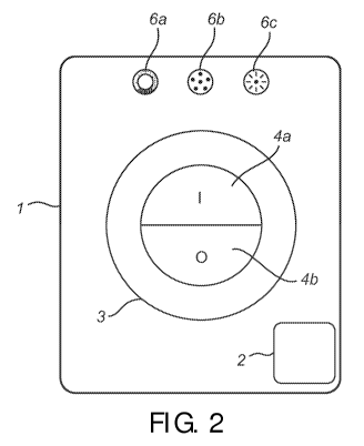
Referring to Fig. 2, there is shown a schematic view of a control device 1
according to an exemplifying embodiment of the present invention. The control
device 1
comprises a touch-sensitive user interface 3. According to the depicted
embodiment, the user
interface 3 comprises a ring-shaped panel 5, sensitive to touch by a user,
whereby the control
CA 02761519 2011-11-08
WO 2010/131163 PCT/IB2010/051992
7
device 1 is provided with user input. The touch-sensitive user interface 3 is
adapted to
visually indicate a range of available values representing at least one visual
parameter, such
as a property of light emitted by light source 10, and to enable a user to
control the
represented property on the basis of a location touched on the user interface
3. The control
device 1 further comprises a communication unit 2 adapted to adjust the
controlled property
by means of communicating, to the light source 10, control signals
corresponding to the user
input. Moreover, the control device comprises an audio signal transmitter (not
shown) which
transmits an audio signal in reply to the control of a visual parameter by
means of the user
interface being operated, in order to audibly identify the controlled visual
parameter. Though
the user interface 3 described with reference to Fig. 2 comprises a ring-
shaped panel 5, the
user interface 3 may comprise shapes other than such a ring-formed shape while
completely
of partially achieving the advantages of the present invention. This is
further described in the
following.
The control device may further comprise an on-button 4a and an off-button 4b
for powering up and powering down the control device 1, respectively.
With further reference to Fig. 2, the control device 1 may further comprise a
plurality of controls, in this particular example in the form of touch-
sensitive activation areas
6a, 6b, 6c. Each touch-sensitive activation area 6a, 6b, 6c may be associated
with at least one
of the properties of light emitted from the light source, e.g. hue,
saturation, brightness, color
temperature and timing properties, and each touch-sensitive activation area
6a, 6b, 6c may be
adapted, when activated, to cause the control device 1 to enable the user to
control the
property associated with the respective activated touch-sensitive activation
area 6a, 6b, 6c via
the touch-sensitive user interface 3.
Fig. 3 shows an example of audio signal character as a function of particular
visual settings. By selecting a first functionality 1 from the control device,
a first audio type
(Type A) is audible for the user. A change of the particular setting within
the first
functionality 1, which may be performed by tapping/sliding a user interface in
the form of a
touch sensitive ring of the control device, still generates the same audio
type (Type A). For
instance, a user may control a visual parameter such as brightness from very
dark to very
bright, while the audio transmitter of the control device generates e.g. a
permanent beep
sound in response thereto. The communication unit of the control device
communicates
control signals, effected by a user operating the user interface, to a device
for which visual
parameters should be controlled. Analogously, a selection of a second
functionality 2 from
the control device renders a second audio type (Type B), distinguishable from
the first audio
CA 02761519 2011-11-08
WO 2010/131163 PCT/IB2010/051992
8
type, e.g. a tick sound. A change of the particular setting within the second
functionality 2
generates the same audio type (Type B). A third functionality 3 renders a
third audio type
(Type C) distinguishable from the first (Type A) and the second (Type B) audio
types, e.g. a
click sound. A change of the particular setting within the third functionality
3 generates the
same audio type (Type Q. Hence, in this particular example, a change within a
functionality
yields a permanent character in the audio signal, whereas a change from one
functionality to
another renders a discontinuous and audibly detectable change in character,
e.g. a different
type of sound.
For a selected functionality, the volume of the audio signal fed back as a
function of the particular selected functionality level is shown in Fig. 4.
The minimum
volume (Vmin) corresponds to a minimum level of a functionality (Fmin), and
the maximum
volume (Vmax) corresponds to a maximum level of a functionality (Fmax). In
case of a visual
parameter such as brightness, Vmin could denote "very dark", while Vmax may
denote "very
bright". Fig. 4a shows a linear increase in volume with an increasing in
functionality from the
minimum level to the maximum level, which can be described in the following as
Volume=k* ([Functionality level]-Fmin)+Vmin,
wherein
k=(Vmax-V min)/(Finax-Fmin)
Fig. 4b shows a non-linear increase in audio signal volume as a function of
selected functionality level. The volume increase is exponential as a function
of change in
functionality level and can therefore be described as
Volume=k*e ([Functionality level]-Fmin) + m
wherein
k=(Vmax-Vmin)/(e (Finax-Fmin) -1)
and
m=Vmin k=Vmin (Vmax-Vmin) ( e (Fmax-Fmin) -1)
The minimum volume Vmin is still audible to users, whereas the maximum
volume Vmax is not too loud for users. The difference between the maximum and
the
minimum volume is sufficiently big for users to perceive a transition in
volume from
minimum to maximum.
CA 02761519 2011-11-08
WO 2010/131163 PCT/IB2010/051992
9
Fig. 5 shows a combination between the type of audio feedback and its volume
level as a function of controlled visual parameters. By selecting a first
functionality 1 from
the control device, a first audio type (Type A) is audible for the user.
Although a change of
the particular setting within the first functionality 1, ranging from Fmm to
Fmax, may be
performed by tapping/sliding the touch sensitive ring of the control device,
the same audio
type (Type A) is generated. However, the volume of the audio signal increases
exponentially,
ranging from Vm,n to Vmax, as a function of an increase from Fmin to Fmax of
the functionality.
For instance, a user may control a visual parameter such as brightness from
very dark to very
bright, while the audio transmitter of the control device generates e.g. a
permanent beep
sound in response thereto. However, the volume of the beep sound increases
from Vmin to
Vmax as the brightness increases from Fmin to Fmax. Analogously, a selection
of a second
functionality 2 from the control device renders a second audio type (Type B),
distinguishable
from the first audio type. A third functionality 3 renders a third audio type
(Type C)
distinguishable from the first (Type A) and the second (Type B) audio types.
Hence, a change
from one functionality to another renders a discontinuous and audibly
detectable change in
sound type. Each functionality has a distinguishable type of sound whereas the
audio
feedback volume is a non-linear function of the functionality level setting.
The discontinuous
change in sound type from one functionality to another informs the user about
the
functionality change.
A functionality level setting is shown for a visual parameter such as e.g.
brightness in Fig. 6. On the control device 1, the touch-sensitive ring of the
user interface 3
has a functionality minimum at the lower left hand side of the ring and a
functionality
maximum at the lower right hand side of the ring, as shown in Fig. 6a. The
interface allows
the user to increase the functionality level by a clockwise sliding of a
finger over the circular
area. Analogously, a functionality level decrease is provided by an anti-
clockwise sliding
over the circular area. Fig. 6b shows a sliding movement of a user finger from
the lower right
hand side to the lower left hand side, i.e. a movement from a maximum level
setting to a
minimum level setting over a sharp transition at the bottom center of the
wheel. Here, the
control device deactivates the audio feedback whilst keeping the maximum level
setting of
the functionality active. In the same way, an increase from a minimum to a
maximum level
setting over the sharp transition at the bottom center of the wheel, as shown
in Fig. 6c, the
control device deactivates the audio feedback whilst keeping the minimum level
setting of
the functionality active.
CA 02761519 2011-11-08
WO 2010/131163 PCT/IB2010/051992
In Fig. 7, the audio signal feedback as a function of functionality level is
shown. A user can control the functionality setting between its minimum and
maximum
value, Fmin and Fmax, respectively. The figure shows that in the range
5 Fmin <= Functionality setting <= Fmax,
the audio signal feedback is active. Analogously, the audio signal feedback is
inactive
10 Fmin> Functionality setting or Finax < Functionality setting
Referring to Fig. 8, the user interface 3 may comprise a substantially
circular
and approximately planar light guide 8 arranged on a PCB 13 (of which only a
portion is
shown). The user interface 3 may further comprise a plurality of
circumferentially spaced
notches 9 (or recesses), each notch 9 (only one notch 9 being referenced by
the numeral 9 in
Fig. 8) being arranged to be capable of receiving a light-emitting element
20a, 20b that, when
received in the respective notch 9 may be substantially radially oriented with
respect to the
light guide 8. According to the exemplifying illustrated embodiment, the light-
emitting
elements 20a, 20b comprise LEDs 20a capable of emitting white light and LEDs
20b capable
of emitting RGB light, the light-emitting elements 20a, 20b being arranged
substantially in a
periodic succession of white and RGB LEDs 20a, 20b. However, such a periodic
succession
is only shown by way of example and other configurations of white LEDs and RBG
LEDs, or
RGB LEDs only, etc. may be implemented according to user needs and/or
application
requirements.
According to the exemplifying illustrated embodiment, the light-emitting
elements 20a, 20b are circumferentially spaced around the light guide 8 with a
spacing that is
substantially constant. It is emphasized that Fig. 8 is schematic and the
present invention
encompasses embodiments comprising arbitrary distances between the
circumferentially
spaced light-emitting elements 20a, 20b.
The distances between the circumferentially spaced light-emitting elements
20a, 20b need not be the same all around the light guide 8. On the contrary,
at least two
adjacent light-emitting elements 20b', 20b" may be arranged such that the
spacing between
the two adjacent light-emitting elements 20b', 20b" is less than the spacing
between other
adjacent light-emitting elements of the plurality of light-emitting elements.
Such a
CA 02761519 2011-11-08
WO 2010/131163 PCT/IB2010/051992
11
configuration is shown at the bottom of the light guide 8 in Fig. 8. This may
be utilized for
increasing the visual contrast at a hard transition, as has been previously
discussed.
According to the illustrated embodiment in Fig. 8, such a hard transition may
be implemented by means of a discontinuity-forming element 23 arranged in the
light guide
8. Hence, the user interface 3 may further comprise a discontinuity-indicating
element 23
adapted to visually indicate a step discontinuity in the range of available
values representing
the at least one property, thus implementing such a hard transition in the
range of available
values representing the currently activated property represented on the user
interface 3. For
implementation of such a discontinuity-indicating element 23 there may be
arranged a
colored region, for example a line 23 according to the illustrated embodiment,
in the light
guide 8.
The light guide 8 may further comprise a light blocking structure 22, or
barrier, between or otherwise being in proximity of a pair of adjacent light-
emitting elements
20b', 20b" as described in the paragraph immediately above, the light-blocking
structure 22
being adapted to substantially block light emitted by light-emitting elements,
for further
controlling the visual characteristics in proximity of the hard transition.
Even though the invention has been described with reference to specific
exemplifying embodiments thereof, many different alterations, modifications
and the like
will become apparent for those skilled in the art. The described embodiments
are therefore
not intended to limit the scope of the invention, as defined by the appended
claims. For
example, a change from a first functionality to a second functionality as
shown in Fig. 3 may
instead render a continuous change from a first audio signal to a second audio
signal.
Furthermore, the audio signal feedback volume as a function of functionality
level may take
on any other relation than those shown in Fig. 4. In fact, any other function
establishing a
volume change with change of functionality level such that a user may
recognize and
distinguish said functionality level change, is feasible. Analogously, any
other function than
the functions presented in Fig. 5, rendering a volume change with change of
functionality
level to supply the user with feedback, may be feasible. Additionally, a
continuous change
from a first audio signal to a second audio signal, independently or in
combination with any
other volume change function, may be feasible.
Moreover, the touch-sensitive ring 5 of the user interface 3 as shown in Fig.
2
may instead have any other form, e.g. a bar or a rectangle, wherein a
functionality minimum
may be situated in the lower side of the bar and a functionality maximum in
the upper side of
the bar.