Note: Descriptions are shown in the official language in which they were submitted.
CA 02761754 2015-05-28
1
CARRIER ELEMENT, BIOLOGICAL WATER TREATMENT SYSTEM AND THEIR
USE, AND METHOD FOR BIOLOGICALLY TREATING WASTE WATER
The invention relates to a carrier element and to a biological water treatment
system. The invention relates
also to use of the carrier element or the biological water treatment system
and to a
method for biologically treating waste water.
TECHNICAL FIELD
In biological water treatment the water is passed through a reactor, where
micro-
organisms are used to convert impurities to harmless end products. In the
reactor
the micro-organisms can be grown suspended or as biofilm on fixed surfaces or
on
carrier elements, which form a floating bed inside the reactor body. When
carrier
elements are used for growing biofilm, the size of the surface area of the
carrier
element is of utmost importance. By increasing the surface of the carrier
element it
is possible to increase the surface area provided for biofilm growth. However,
this
often increases the structural complexity of the carrier element.
The water treatment process may be conducted aerobically, which means that
oxygen or air is supplied to the reactor. A large amount of oxygen is consumed
in
the process because of biochemical oxidation of organic and inorganic
compounds. At the same time the mass of the biofilm increases on the carrier
surfaces due to growth and bounding of solids. However, wastewater impurities,
oxygen and micro-organisms should be able to maintain a sufficient contact
with
each other in order to guarantee the purification results.
It has been sometimes assumed that in a process employing freely moving
carriers in a reactor the mechanical abrasion and high flow rates might wear
away
biofilm growing on the carrier surfaces, which could reduce the efficiency of
the
process. This assumption has led to an attempt to reduce the flow rate through
the
carrier by increasing the structural complexity and the size of the carrier.
CA 02761754 2011-11-10
WO 2010/130881 PCT/F12010/050389
2
A known problem in the existing processes is the carrier clogging caused by
excess sludge growth and precipitation, especially when carrier elements with
complex structure are used. If the biofilm on the carrier surface grows too
much,
and the carrier is clogged, the purification results of the process are
deteriorated.
The micro-organisms do not come into contact with the water impurities and/or
oxygen. The problem may be solved by increasing the mixing through air supply
to
the reactor, which increases the energy consumption of the process.
One effort to solve the problem of clogging has been made by increasing the
size
of the carrier element. Document EP 750 591 discloses the use of carrier
elements
which have the surface thereof partly protected against collision with the
surfaces
of other carrier elements in a biological water or wastewater purification
process.
The carrier elements have a length, width and/or height exceeding 1.5 cm,
preferably in the interval ranging from 2.5 to 10 cm, particularly in the
interval
ranging from 3 to 6 cm.
Document EP 575 314 discloses a method for water purification in which waste
water is allowed to flow through a reactor containing carriers on which
biofilm is
grown. The carriers are in the form of pieces of a tube with linear dimensions
in
the range 0.2 ¨ 3 cm, particularly 0.5 ¨ 1.5 cm and manufactured of soft
plastic by
extrusion method. The aim has been to maximise the surface area of the carrier
for biofilm growth.
Document DE 102 31 217 A1 discloses a tubular element manufactured by
extruding and intended to be used as a packing element in stationary packed
beds. The element has a unitary diameter through its body length, but its ends
may be straight or conical.
OBJECT AND SUMMARY OF THE INVENTION
An object of this invention is to minimise or even eliminate the disadvantages
existing in the prior art.
CA 02761754 2015-05-28
3
An object is also to provide a carrier element that minimises the risk for
carrier
element clogging.
A further object of this invention is to provide a carrier element and method
that
enables an effective contact between the biofilm and the impurities and oxygen
in
the water.
A still further object of the invention is to provide a carrier element and a
biological
water treatment system with which the energy consumption of the treatment
process may be decreased.
These objects are attained with the present invention having the
characteristics
presented below.
DETAILED DESCRIPTION OF THE INVENTION
Typical carrier element according to the present invention for an aerobic
biological
water treatment system has
- a first end and a second end at a distance from each other, the maximum
diameter of the first end being larger than the maximum diameter of the second
end,
- biofilm growing surface structures that extend from the first end to the
second
end and from inner part of the element towards periphery of the element and,
- at least two support structures that encircle the growing surface structures
at the
periphery of the element and connect the growing surface structures to each
other,
the support structures defining the outer boundary surface of the carrier
element,
whereby the support structures are spaced from each other so that apertures
allowing access to the biofilm growing surface structures are formed in the
periphery of the element between the support structures.
Typical biological water treatment system according to the present invention
comprises a treatment reactor, which has a reactor volume defined by reactor
CA 02761754 2011-11-10
WO 2010/130881 PCT/F12010/050389
4
wall(s) and bottom, which reactor volume comprises freely moving carrier
elements according to the invention.
Typical method for biologically treating waste water according to the present
invention comprises
- leading water to be treated or purified to a treatment reactor comprising
carrier
elements which are freely moving, suspended in the water, in the treatment
reactor and on which a biofilm is grown,
- feeding air or oxygen to the treatment reactor, and
- leading treated or purified water away from the treatment reactor,
- using carrier elements according to the invention in the treatment
reactor.
Now it has been surprisingly found out that by proper design of the carrier
element
it possible to obtain a carrier element which provides a high surface area
and, at
the same time, an open structure that enables the micro-organisms of the
biofilm
come into contact with impurities in water and oxygen. The open structure of
the
carrier element according to the present invention ensures an effective flow
through and flushing of the carrier element, whereby excessive biofilm growth
on
the internal walls and clogging of the carrier element are prevented or at
least
minimised. The carrier element has also a support structure that protects the
internal walls of the element and makes it mechanically strong. All these
properties
make the carrier element more effective and more energy efficient whereby the
energy consumption of the treatment process may be reduced, either by
downscaling of the size of the reactor or by using less added aeration for
mixing
and for oxygen supply.
Carrier element according to the present invention comprises biofilm growing
surface structures that are also in this application called internal walls.
These two
terms are in this context completely interchangeable. The internal walls are
long
flat structures that function as surfaces on which the biofilm grows. The
internal
walls form a cross-like or a star-like structure and they extend towards the
peripheral surface of the carrier element. Preferably all internal walls of
the carrier
element extend from a starting point in the centre of the element towards the
CA 02761754 2011-11-10
WO 2010/130881 PCT/F12010/050389
periphery of the element, and they are typically in contact with each other at
the
starting point. In other words, the central longitudinal axis of the carrier
element
may be closed for water flow and the carrier element may comprise a solid
longitudinal axis to which the internal walls are attached. The internal walls
give
5 added mechanical strength to the carrier element structure, especially
when the
overall size of the element is small. Typically, a carrier element according
to the
present invention has 4 to 8 internal walls, more preferably 6 to 8 internal
walls.
The internal walls are preferably arranged in symmetrical star-like
arrangement, so
that the individual walls are equidistantly spaced from each other. The wall
thickness is typically 0.2 ¨ 1.0 mm, more typically 0.4 ¨ 0.8 mm.
According to one embodiment of the invention every other of the internal walls
may be shaped as a triangle, preferably as a right-angled triangle. When the
internal wall has triangular shape, the base of the triangle is situated at
the second
end of the carrier element, where it is arranged in connection with the other
internal walls. The vertex of the triangular wall is arranged in connection
with a
support structure at the first end of the carrier element.
The reinforcing support structures of the carrier element are arranged to
encircle
the internal walls at the periphery of the element, thus further increasing
the
mechanical strength of the carrier element. Typically the support structures
are
narrow belt-like structure that surrounds the internal walls in the periphery
of the
element. The support structures defining the outer boundary surface of the
carrier
element. This means that the support structures define the partially virtual
outer
boundary surface of the carrier element. Usually there is more than one
support
structure, typically two support structures, more typically three support
structures.
In case of three support structures, the first structure is typically arranged
near the
first end of the carrier element, the second is arranged near the second end
of the
carrier element and the third in the middle section between the first and
second
end. The reinforcing support structure is normally continuous ring-like
structure
having a certain height in carrier element's length direction. It is also
possible that
an individual support structure is made of a plurality of thin string-like
members,
which are twisted together or arranged at short distance from each other. In
case
CA 02761754 2011-11-10
WO 2010/130881 PCT/F12010/050389
6
the support structure is made from a plurality of thin string-like members,
the
distance between adjacent support structures is clearly larger than the
distance
between adjacent string-like members of the individual single support
structure.
The support structure also connects the internal walls to each other at the
periphery of the carrier element. Thus lateral openings or apertures are
formed to
the peripheral surface of the carrier element. The apertures enable the
efficient
entry of water and air to the inner part of the carrier element. Efficient
flow through
and flushing the carrier element is not important only in view of the mass
transfer
of oxygen, substrates and metabolism in and out from the inner part of the
carrier
element, but the flow also exposes the biofilm on the surfaces of the internal
walls
for abrasion which decreases the excessive growth of the biofilm and minimises
the risk for the clogging of the element. For example, the carrier element may
have
16 lateral apertures at periphery of the element that give a high total
openness for
the element.
The growing surfaces and support structures of the carrier element define also
void spaces inside the carrier element. The carrier element of the present
invention is designed so that the openness of the carrier element is
maximised,
whereby an effective mass transfer is maintained even in the situations when
the
carrier element comprises high amount of biofilm on growing surfaces and other
solids inside its structure. According to one embodiment of the invention the
apertures in the outer boundary surface in the periphery of the carrier
element
body against the cross sectional area of a similar solid element boundary
surface
are over 42 %, preferably over 45 %, more preferably over 48 %, still more
preferably over 50 %. The high surface area and openness of the carrier
element
also enable very efficient biofilm activity and thus high treatment
efficiency. The
open structure of the carrier makes it possible also to increase the
concentration of
suspended solids in the incoming wastewater flow and inside the reactor
compared to treatment processes using prior art carrier elements.
According to one embodiment of the invention the carrier element is conical in
shape and/or the cross-sections of the first and second ends are circular. The
CA 02761754 2011-11-10
WO 2010/130881 PCT/F12010/050389
7
conical shape of the carrier element improves the movement and rotation of the
element in the reactor during the mixing. According to one preferred
embodiment
the diameter of a carrier increases from the second end towards the first end
of
the carrier. This means that the diameter of the first end is at least 15 %,
typically
20 ¨ 55 %, more typically 25 ¨ 40 %, most typically 30 ¨ 35 % larger than the
diameter of the second end. It has been noticed that the energy efficiency of
the
process may be improved even by 30 % compared to conventional systems when
small conical carrier elements according to the present invention are used.
According to one embodiment of the invention the first end of the carrier
element
has a diameter in the range of 11.0 ¨ 13.6 mm, preferably 11.7 ¨ 13.1 mm, more
preferably 12.3 ¨ 12.7 mm.
According to one embodiment of the invention the second end of the carrier
element has a diameter in the range of 8.5 ¨ 11.3 mm, preferably 9.1 ¨ 10.8
mm,
and particularly more preferably 9.4 ¨ 10.5 mm.
According to one embodiment of the invention the ratio of the diameter of the
first
end and the diameter of the second end of the carrier element is over 1.2,
preferably over 1.25, more preferably over 1.29.
According to one embodiment of the invention the length of the carrier
element',
measured perpendicularly from the first end to the second end, is 11.0 ¨ 14.9
mm,
preferably 11.6 ¨ 13.8 mm, more preferably 12.2 ¨ 12.7 mm.
The size and design of the carrier element enable the carrier elements to move
effectively in the whole reactor volume when mixing is achieved by using the
aeration system of the reactor. This ensures a proper mixing of the carrier
elements with the water to be treated and a continuous contact to air, water
and
substrates. Thus the whole reactor volume is efficiently mixed and
consequently
there is no "dead" or "unused" space inside the reactor. This means that in
order to
achieve the same treatment results as with conventional reactor systems it is
possible to scale down the reactor size and/or the carrier filling degree. A
smaller
CA 02761754 2011-11-10
WO 2010/130881 PCT/F12010/050389
8
reactor needs less aeration and less mixing, whereby the overall energy
consumption of the treatment process is decreased. On the other hand by using
the carrier elements according to the present invention and a reactor of
conventional size, it is possible to increase the treatment capacity of the
process.
At the same time, the size and design of the carrier element provide a large
carrier
surface for biofilm growing and optimal flowing conditions inside and around
the
carrier element. The carrier construction effectively prevents the clogging of
the
carrier interior, provides a adequate flow of oxygen and impurities to the
biofilm,
but at the same time protects the biofilm from abrasion and washing away.
Density of the carrier element is normally close to density of the water at
process
temperature. This guarantees that the carrier elements are kept suspended
throughout the reactor volume, and they are not accumulated to the top or
bottom
of the reactor. Typically the density of the carrier element is 0.92 ¨ 0.99
kg/dm3,
preferably 0.93 ¨ 0.98 kg/dm3, more preferably 0.94 ¨ 0.97 kg/dm3.
According to one embodiment of the invention the carrier element is made of
hard
plastic material, such as polyethylene, polypropylene or their mixture, by
injection
moulding. Carrier element is preferably made of polyethylene, more preferably
recycled polyethylene. When the small carrier elements are made by injection
moulding from hard plastic the resulting element structure is stable and
mechanically durable even if the carrier element circumference and periphery
are
kept open. Good mechanical strength of the element increases the overall
lifetime
of the carrier element, thus reducing costs that are associated with the
renewal of
carrier elements due to mechanical wear and breakdown. Carrier element may be
made of recycled or virgin plastic material.
According to one embodiment of the invention the biological water treatment
system comprises two or more treatment reactors arranged in parallel or in
series.
In other words, it is possible to operate water treatment process utilising
the carrier
elements according to the present invention in one or several stages, which
stages
may be operated in series or in parallel. In order to keep the carrier
elements
CA 02761754 2011-11-10
WO 2010/130881 PCT/F12010/050389
9
according to the present invention inside the reactor screens are placed to
the
outlet and inlet of the reactor. Thus outflow of the carrier elements from the
reactor
is prevented.
According to one embodiment of the invention the filling degree of carrier
elements
in the reactor is between 14 ¨ 28 volume-%, preferably 16 ¨ 26 volume-%, more
preferably 18 ¨ 25 volume-%, still more preferably 20 ¨ 25 volume-% of the
total
reactor volume. The filling degree is lower than in the prior art processes
using
conventional carrier elements. The carrier elements according to the invention
have high surface area and very efficient mass transfer to and from the
biofilm,
whereby treatment efficiency is achieved with lower number of the carrier
elements. The low filling degree of the carrier elements in the reactor
improves
generally the process and mixing efficiency of the carrier elements, which
decreases both the need of mixing energy and the clogging tendency of the
outlet
screen.
According to one embodiment of the invention treated or purified water is led
to a
clarifier, and sludge is recycled from the clarifier back to the treatment
reactor.
Thus the biological water treatment system comprises a clarifier arranged
after the
treatment reactor and connections for recycling sludge from clarifier back to
treatment reactor. Thus a part of the sludge may be recycled back from the
clarifier to treatment reactor comprising carrier elements according to the
present
invention. The open and mechanically strong structure of the carrier element
tolerates also returning of recycled sludge without clogging. Addition of
sludge to
the treatment reactor makes it also possible to further increase the process
efficiency by increasing the biomass inside the reactor or reduce the filling
degree
of the reactor as a part of the biofilm may be replaced by recycled sludge.
It is possible to arrange in the upper part of the treatment reactor an output
connection, which is connected to the clarifier. According to one embodiment
of
the invention treated or purified water is led away from the upper part of the
treatment reactor.
CA 02761754 2011-11-10
WO 2010/130881 PCT/F12010/050389
According to one embodiment of the volume of the returned and/or recycled
sludge flow is normally 2 ¨ 15 volume-%, preferably 3 ¨ 12 volume-%, more
preferably 5 ¨ 10 volume-% of the incoming flow of water to be treated or
purified.
The clarifier may be any type of gravity settler, dissolved air flotation
(DAF), or it
5 may be a lamella clarifier. Generally the returning of the sludge to the
reactor
supports the growth of microorganisms. Earlier it is assumed that this would
lead
to excessive biofilm growth and clogging of the carrier elements. The openness
of
the carrier element according to the present invention allows the sludge
return to
the reactor without risk of clogging. With the return sludge a higher biomass
10 concentration and higher diversity of micro-organisms is achieved inside
the
reactor employing carrier elements according to the present invention. Use of
return sludge also significantly shortens the start-up time of the biological
water
treatment process.
The biological water treatment system according to the present invention may
take
care of the whole biological treatment of the purification process. It is also
possible
to arrange an activated sludge process between the treatment reactor and
clarifier.
In this case the water/sludge mixture is led from the treatment reactor
comprising
the carrier elements to an activated sludge process, from which the overflow
comprising mainly water phase is led to the following clarifier. The
biological water
treatment system may also be placed after an anaerobic treatment stage.
A water treatment reactor comprising carrier elements according to the present
invention arranged in front of an activated sludge process improves also the
functioning of the activated sludge process. Quality of sludge is especially
improved, which means that the quality of the microorganisms in the sludge is
good and sludge is easily separable and sedimentable.
The treatment capacity of the treatment system may be varied by changing the
biomass concentration in the treatment reactor. This can be done via changing
the
volume of the return sludge flow and/or by changing the filling degree of the
carrier
media. For example, as the carrier elements according to the present invention
allow the return of the sludge to the reactor, it is possible to react faster
to changes
CA 02761754 2011-11-10
WO 2010/130881 PCT/F12010/050389
11
in the incoming wastewater quality and treatment process circumstances by
changing the return sludge flow. This makes the whole treatment process more
tolerant against peaks of organic load and variations in incoming flow rate.
According to one embodiment of the invention the biological water treatment
system comprises a reactor having a bottom aeration system comprising one or
more grid-like aeration elements. The bottom aeration system enables the
carrier
elements to move freely in the whole reactor volume having continuous contact
to
air, water and substrates. Sufficient mixing with low aeration energy
consumption
is ensured by the new carrier design and properly designed and implemented
aeration system. The bottom aeration system comprising grid-like aeration
elements is in direct contact with the total treatment reactor volume and with
the
carrier elements. In other words, it has not been separated from the carrier
elements by a screen or the like. The carrier elements may have direct
physical
contact with the aeration system elements, without the aeration system
elements
being subjected to detrimental wear or impacts. Thus it is not necessary to
divide
the treatment reactor volume to different zones or "compartments", but the
treatment reactor volume is preferably one single undivided three-dimensional
space.
Preferably the aeration system covers the whole bottom of the reactor vessel
and
creates optimum mixing and sufficient aeration for the process. The tubular
aeration system comprises a number of grid-like aeration elements, which
comprise a main air feed pipe and a number of air diffusers arranged
perpendicularly to the air feed pipe. Air/oxygen is led to inside the aeration
system
tubes inside the main air feed pipe and from it to air diffusers. The
air/oxygen
emerges from the air diffuser perforations as small air bubbles.
According to one embodiment of the invention one or several of the air
diffusers
may be made of plastic material, such as polyethylene or polyester. Use of
plastic
material in air diffusers enables production of smaller perforations to the
diffusers,
whereby also the size of the bubbles emerging from the perforations is
reduced.
Small bubble size gives more contact surface between the air bubble and water
CA 02761754 2011-11-10
WO 2010/130881 PCT/F12010/050389
12
and microorganisms in the reactor. This makes the oxygen transfer to water and
to
microorganisms more efficient, whereby the same aeration result is obtained by
less consumption of air. This leads significant savings in energy.
The aeration system may also be arranged to be self-flushing, thus preventing
the
main air feed pipes and diffusers from blocking and requiring minimum amount
of
maintenance work from the operating personnel. Small pipe-like protrusions are
arranged to the lower side of the main air feed pipes of the aeration grids.
These
protrusions are open to the surroundings and the aeration system may be
flushed
through these protrusions automatically. This prevents the contamination of
the
main air feed pipes and diffusers by excessive growth of microorganism or by
accumulation of dirt inside them.
According to one embodiment of the invention the carrier elements are brought
in
a counterclockwise rotation against the incoming feed flow in the reactor.
This
counter current mixing prevents or minimises the possibility of straight flow
from
the feed inlet to outlet screen and ensures sufficient delay time for effluent
inside
the reactor. The rotation direction of the carrier elements in the reactor may
be
adjusted with air distribution valves.
According to one embodiment of the invention the water treatment system
comprises an oxygen sensor that is arranged in connection with the treatment
reactor to measure oxygen concentration in the reactor and an adjustment means
for adjusting the aeration of the reactor according to the measured oxygen
concentration. Thus it is possible to optimise the aeration energy consumption
by
continuously measuring oxygen concentration in the reactor by using suitable
oxygen sensors and by adjusting the aeration of the reactor according to the
measured oxygen concentration. Thus unnecessary aeration, which is performed
only in order to be on the safe side, is decreased. The oxygen sensor is
preferably
arranged on the outlet of the treatment reactor, where it may be protected by
a
reactor outlet screen, which prevents the collision of the carrier elements to
the
oxygen sensor. The aeration of the reactor may be adjusted on-line or
CA 02761754 2011-11-10
WO 2010/130881 PCT/F12010/050389
13
continuously with the adjustment means based on the measurement values
obtained from the sensor.
The aeration system described in this application may be used also with other
carrier elements, differing from those described in this application. The
aeration
system may still provide a number of benefits and advantages.
Typical carrier element or the biological water treatment system according to
the
present invention is used for treating or purifying waste water from food
and/or
beverage industry, petrochemical industry or municipal waste water. In some
advantageous embodiments of the invention the waste water to be treated is
essentially free of fibres.
Typical carrier element or the biological water treatment system according to
the
present invention is used for treating or purifying waste water having a value
for
the chemical oxygen demand (COD) of at least 200 mg/I, typically 300 ¨ 4000
mg/I, more typically 400 ¨ 2000 mg/I, most typically 500 ¨ 1500 mg/I.
FIGURES
The figures are to be taken as purely schematical and are not to be construed
as
limiting the scope of the claims. The invention is described in more detail
with
reference to the enclosed figures, where
Figure 1 shows a carrier element according to one embodiment of the present
invention,
Figure 2 shows a side view of a carrier element according to one
embodiment
of the present invention,
Figure 3A shows a top view of a carrier element according to one embodiment of
the present invention,
CA 02761754 2011-11-10
WO 2010/130881 PCT/F12010/050389
14
Figure 3B shows a bottom view of a carrier element according to one
embodiment of the present invention, and
Figure 4 shows schematically a water treatment process according to one
embodiment of the present invention.
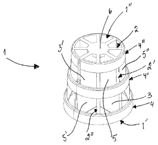
In Figure 1 is shown a carrier element according to one embodiment of the
present
invention. The carrier element 1 has a first circular end 1' and a second
circular
end 1'. A number of internal walls 2, 2', 2" extend from the first end 1' to
the
second end 1". Internal wall 2 has a shape of a triangle, whereas internal
wall 2' is
quadrangular in shape. The internal walls 2, 2', 2" provide flat continuous
surfaces
3, 3' for growing of the biofilm. Support structures 4, 4', 4" surround the
internal
walls 2, 2', 2" and define the periphery of the carrier element 1. Support
structures
4, 4', 4" make also the carrier element structure resistant for abrasion and
mechanical stresses. At the same time the support structures 4, 4', 4" are
spaced
so widely apart from each other that apertures 5, 5', 5" are formed to the
periphery
of the carrier element 1. These apertures 5, 5', 5" enable the transport of
impurities, water and oxygen in and out of the carrier element 1 and to the
biofilm
growing on the surfaces of the internal walls 2, 2', 2".
In Figure 2 is shown a side view of a carrier element according to one
embodiment
of the present invention. The reference numbering corresponds to that of Fig.
1. It
can be observed that the carrier element 1 is slightly conical, meaning that
the
diameter of the first end 1' is larger than the diameter of the second end 1".
In the
embodiment shown in Fig. 2 all the support structures 4, 4', 4" have the same
width in the length direction L of the carrier element 1, indicated in the
Fig. 2 by an
arrow L. It is also possible that the width of the support structures 4, 4',
4" may
vary from each other.
In Figure 3A is shown a top view of a carrier element according to one
embodiment of the present invention. The support structures 4, 4', 4" can be
observed due to the conical shape of the carrier element 1, as the diameter of
the
individual support structures is decreasing towards the second end 1" of the
CA 02761754 2015-05-28
carrier element. Thus the first support structure 4 has a larger diameter than
the
following and the last support structure 4', 4". The internal walls 2, 2', 2"
are
connected with each other in the second end 1" of the carrier element 1 by a
plate
6.
5
In Figure 3B is shown a bottom view of a carrier element according to one
embodiment of the present invention. The reference numbering corresponds to
that of preceding Figures. First internal walls 2, 2" are connected to each
other in
the first end 1' of the carrier element 1, at the centre of the element, and
forming a
10 cross-like structure. Second the internal walls 2', 2¨ do not reach to
the centre of
carrier element 1 in the first end 1' of the element 1 and they do not connect
with
each other or with the first portion of the internal walls. One second
internal wall 2',
2¨ is situated in between two of the first internal walls 2, 2". All the
internal walls
are connected with each other at the periphery of the carrier element by the
aid of
15 support structures 4, 4'.
In Figure 4 is shown schematically a water treatment process according to one
embodiment of the present invention. Water to be treated A is led to a
treatment
reactor 40 comprising carrier elements 41 according to the present invention.
Air
or oxygen is fed to the reactor 40 by using an aeration system 42 comprising a
number of grid-like aeration elements 43, 43', 43", 43¨. Air or oxygen is fed
to the
aeration system 42 by using a blower 44. One aeration element 43 comprises a
main air feeding pipe and a number of air diffusers 45, 45'. Small holes or
perforations (not shown) are formed to the air diffusers, so that the air can
be
expelled from the aeration system 42 in form of small bubbles. The formed
bubbles keep the carrier elements 41 in the move and suspended in whole volume
of the reactor 40.
An output connection 46 is arranged in the upper part of the treatment reactor
40,
from which connection biologically treated water is taken out of the reactor
40 and
led to the clarifier unit 47. In the clarifier unit 47 the treated water is
allowed to
settle, so that sludge is sedimented on the bottom 47' of the clarifier unit
47. From
the bottom 47' the sludge is taken out, and a part of it is recirculated back
to
CA 02761754 2011-11-10
WO 2010/130881 PCT/F12010/050389
16
treatment reactor 40 by using pipeline 48. Purified water is taken out from
the
upper part of the clarifier unit 47 through connection 49.
Even if the invention was described with reference to what at present seems to
be
the most practical and preferred embodiments, it is appreciated that the
invention
shall not be limited to the embodiments described above, but the invention is
intended to cover also different modifications and equivalent technical
solutions
within the scope of the enclosed claims.