Note: Descriptions are shown in the official language in which they were submitted.
CA 02761779 2011-11-10
1
Security element for value document
The present invention relates to the technical field of security
elements for value documents. It applies more particularly but not
specifically to
the printing of a security element for such a value document, such as for
example a fiduciary or similar document.
By "fiduciary document" within the meaning of the invention is meant
all documents such as bank notes, checks, banking cards, used for transmitting
a sum of money.
By "similar document" is meant all documents issued by a State
office for certifying the identity of a person, [or] his right to drive a
vehicle, such
as in particular the identity card, the passport, the driver's license, etc.
Also
meant by this expression is any document used to authenticate an object of
value such as for example a tag attached to a luxury garment. Also meant is
any document used to authenticate payment of a tax such as a tax sticker.
In the field of value documents, of banknotes in particular, it is known
to apply one or more security elements of various types in order to protect
these
documents from counterfeiting.
There exist different types of security elements, including in particular
so-called "first level" security elements.
Such a security element is difficult to make while still being easily
identifiable by a general public during simple attentive observation.
This security element often has a relatively complex graphic design
such as a continuous solid, guilloche patterns, a banknote style and employs
various printing techniques such as offset, silkscreen, intaglio, flexography,
typography, etc.
The result of the combination of these printing techniques and of
these complex graphic designs is a security element having a sharpness of
styling, interlaced designs as well as combinations of effects that are very
difficult to reproduce with reproduction equipment available to the general
public
I
CA 02761779 2011-11-10
2
(scanner, color laser or ink jet printers, etc.) and/or with standard printing
equipment.
First-level security measures already known in the state of the art,
particularly from document EP 1 384 595, include a security element comprising
a latent image made according to a first technique.
In this document, according to this first technique, the security
element is made by a relief printing process. The security element comprises a
first array of lines extending along one predefined orientation and a second
array of lines extending along another orientation, perpendicularly for
example,
thus forming a sharp distinction between the two arrays. For example, the
second array forms a design of the latent image, that can include information,
and the second array forms the background of the latent image.
The design of the latent image does not appear by direct observation
orthogonal to the plane of the security element but does appear at a certain
predefined angle of observation, particularly a grazing angle. The relief of
the
security element can possibly be covered by ink. In addition, several latent
images can be interlaced according to this first technique.
Also known in the state of the art, from document EP 1 580 020 in
particular, is a security element comprising a latent image made according to
a
second technique.
In this document, the security element comprises two distinct zones
each comprising a set of furrows, each furrow having one steep slope and one
shallow slope. The first zone forms for example the background of the latent
images while the second zone forms a design hidden in the background when
the security element is observed from a direction normal to the plane of the
latter.
The shallow slopes of the furrows of the first set are oriented in a first
common direction, while the shallow slopes of the furrows of the second set
are
oriented in a second common direction opposite to the first direction.
Thus, when exposed to a light source, the security element reflects a
beam of light along two different favored directions depending on the
inclination
I
CA 02761779 2011-11-10
3
of the slopes, so that a contrast appears between the two zones, under a
predefined observation angle, revealing the hidden design.
The disadvantage of these techniques is that it is necessary to
sharply tilt the value document to obtain sufficient contrast between the two
zones and thus reveal the latent image. The design must also have relatively
simple graphics to appear in a way that is legible in grazing observation.
The invention has the particular goal of proposing a first level security
element identifiable under any angle of observation while still allowing the
formation of complex designs.
To this end, the invention has as its object a security element for a
value document comprising an array of lines in relief, each line comprising at
least one flank defining an angle of inclination with respect to a direction
normal
to the array, characterized in that the angle of inclination of the flank of
at least
one line of the array varies gradually along that line so as to form in
reflected
light a optical shading effect that changes according to an angle of
observation
of the security element.
Thanks to the invention, due to the variation of the angle of
inclination along the line, the light is reflected along several preferred
directions
by the flank of the line and the distribution of the reflected light intensity
on the
array of lines produces the optical shading effect that changes according to
the
angle of observation. This element also offers tactile relief.
Thus, by a simple small amplitude tilting motion of the sheet with
respect to a direction normal to the substrate of the document, a succession
of
contrasts from lightest to darkest, each corresponding to a different light
distribution, propagates by degrees, generating an immediately detectable
dynamic effect. In addition, complex designs are formed in the array thanks to
the diversity of gradations that can be included by variation of the
inclination of
the flanks of the lines. The image resulting therefrom makes it possible to
obtain
additional effects compared with prior art and produces in particular an
easily
detectable dynamic effect.
By optical shading effect is meant a progressive, gradual transition
from a bright gradation to a darker gradation. Of course zones of abrupt
CA 02761779 2011-11-10
4
transitions can be inserted between the zones having progressive transitions
without it departing from the scope of the invention.
The technical problem is also solved thanks to a security element for
a value document comprising an array of lines in relief, each line comprising
a
flank defining an angle of inclination with respect to a direction normal to
the
array, characterized in that the angle of inclination of the flank of at least
two
adjacent lines of the array varies gradually from one line to another so as to
form in reflected light a optical shading effect that changes depending on the
angle of observation of the security element.
Thus, in this case, the angle of inclination is for example constant
along each line of the array but varies gradually from one line of the array
to
another, which produces a dynamic effect depending on the angle of
observation, as in the foregoing.
This is an alternative solution to the first solution to the technical
problem posed: instead of having a variation of the angle of inclination of
the
slope of the same line, the inclination of the slope varies from one line in
the
network to another.
It can be considered that this second embodiment is a limiting
hypothetical case of the first embodiment wherein the variation of the angle
of
inclination along the line is so slight that it appears to be substantially
nil and
wherein the angles of inclination of the two flanks of two contiguous lines
with
the same orientation are distinct.
In these two embodiments, preferably, the arrays are made up of
continuous lines having a small spacing, and preferably contiguous. These
lines
are in addition preferably parallel or quasi-parallel rectilinear (vertical,
horizontal
or oblique).
In one variation, a line can have a zigzag shape, made up of a
plurality of longer or shorter segments, each segment having an angle
different
from those to which it is directly attached.
In another variation, the lines can also be curvilinear, circular or
spiral-shaped over at least part of the lines.
CA 02761779 2011-11-10
Thanks to these different possible line shapes, the designs can be
more or less complex.
More generally, the lines can be arbitrarily shaped with gentle or
angular bends having open or closed, concave or convex shapes
5 The widths
of the lines are preferably constant and mutually equal.
As a variation, they can be different and/or gradually or abruptly changing,
widening or narrowing within the same line. The intrinsic features of each
line
such as its width, its length, its general shape can vary from one line to
another.
Preferably, the relief arrays are formed by the intaglio printing
technique with or without ink. lnkless intaglio printing is commonly
designated
by the term embossing stamp technique. The embossing stamp can be made
for example on a substrate of the value document after prior application of a
first
layer of ink. The array in relief is then embossed at least partially over
this first
layer of ink.
The ink is chosen for example, and without limitation, from among an
ink with an iridescent optical effect, an ink with a variable optical effect
(OVI
type), a magnetic ink with a variable optical effect (OVMI type), and a liquid
crystal ink. The ink can also be an ink invisible under white light and
visible
under ultraviolet and/or infrared radiation.
In this case, the changing optical effects produced by the geometric
relief of each line of the array are advantageously coupled with the optical
properties of the ink to arrive at a first-level security element that is
complex and
difficult to reproduce.
Preferably, the variation of the angle of inclination is periodic or
pseudo-periodic. This periodicity of the angular variations of the flanks of
the
lines makes it possible to create an optical effect which propagates by
degrees
when the security element is tilted.
In this case, the variation in the angle of inclination can be spatially
modulated in frequency so as to encode or incorporate information in the line
and/or the array. Thus, in this case, it is possible to make characters,
complex
drawings appear by modulating portions of the lines of the array with high
frequencies compared to the rest of the array.
CA 02761779 2011-11-10
6
For example, the periodic or pseudo-periodic variation of the angle of
inclination is sinusoidal or helical over at least part of the line.
Further, the angle of inclination of the flank can vary by predefined
steps along the line. The predefined step can possibly be variable.
Preferably, each line includes another flank in which the two flanks
meet in a longitudinal ridge of the line and the inclination angle of the
other flank
varies gradually along the line. Thus, in this case, the furrows formed by the
facing flanks of the two contiguous lines of the array can have a constant
depth.
Further, it is possible to create a symmetrical optical effect by having
the angles vary in a symmetrical fashion (mirror effect) on the two facing
flanks
of two contiguous lines and/or on the two flanks of the same line.
Preferably, the lines of the array are contiguous. Squeezing the lines
together allows the optical shading effect to be amplified.
The element can include at least the first and second contiguous
lines wherein the variations of inclination of the flanks of the two lines
with the
same orientation are offset with respect to one another along the lines.
In this case, advantageously, this offset of the variations from one
line to the other creates an effect of propagation by degrees of the design
formed by the array when a tilt is voluntarily applied to the security
element.
Preferably, the width of a line is comprised between 10 micrometers
and 2 millimeters, preferably between 100 micrometers and 1 millimeter. The
line has preferably a height comprised between 0 and 200 micrometers,
preferably approximately equal to 100 micrometers. The period of the variation
is for example greater than 0.1 millimeters, preferably comprised between 0.5
and 20 millimeters.
Preferably, the array is covered with a protective varnish so as to
protect it in particular from attack by its external environment.
The array can in addition be made at least partially on a diffractive
structure such as a holographic patch or strip.
In addition the flank(s) can have a transverse section having a
generally curvilinear concave or convex shape or a generally rectilinear shape
CA 02761779 2011-11-10
7
with at least one concave or convex incidence break. This makes it possible in
particular to further increase the complexity of the optical effects.
A security element according to the invention can also include one or
more of the features according to which:
- each line includes another flank, the two flanks joining in a
longitudinal ridge of the line; the angle of inclination of the other flank
is constant along the line;
- the two facing flanks of two contiguous lines of the array are joined,
forming a furrow having constant depth along the lines;
- the two facing flanks of two contiguous lines are joined, forming a
furrow having variable depth along the lines, one of the flanks having
a constant angle of inclination along its line, zero for example.
The invention also has as its object a plate for intaglio printing,
characterized in that it comprises a zone capable of creating by printing onto
a
substrate a security element according to the invention, the zone comprising
at
least one engraved furrow with a shape complementary to that of a line of the
array of the element.
A plate according to the invention can include one or more of the
features according to which:
- the furrow has a stepped profile;
- the stepped profile has individual steps having a size less than or
equal to five microns.
The invention also has as its object a method for manufacturing a
plate for intaglio printing according to the invention, characterized in that
it
includes a step consisting of engraving the plate using an engraving tool
controlled by a computer according to a program defining the variation of the
angle of inclination of the flank of each line of the array.
A method according to the invention can include the feature
according to which the engraving tool is a laser engraving tool or a precision
mechanical milling tool.
The invention also has as its object a value document bearing a
security element according to the invention.
CA 02761779 2011-11-10
8
Finally, the invention also has as its object a substrate for a value
document according to the invention wherein the security element is obtained
by intaglio printing or by embossing by means of a plate according to the
invention. The embossing can be performed hot or cold.
Other features and advantages of the invention will appear in the
light of the description that follows, made with reference to the appended
drawings wherein:
- Figure 1 shows a value document such as a banknote including a
security element according to a first embodiment of the invention;
- Figures 2 and 3 show an array of lines of the security element of
Figure 1 from two observation angles, respectively 01 and 02;
- Figure 4 shows a perspective view of three contiguous lines of the
array of Figures 2 and 3;
- Figures 5 and 6 show the longitudinal variation of the height of a
longitudinal ridge of one of the lines of the array of Figure 4 along
which the variation of the angle of one of its flanks is respectively
sinusoidal and triangular and Figures 5A, 5B and 6A, 6B show cross
section views along lines A-A and B-B respectively of Figures 5 and
6;
- Figure 7 shows a perspective view of three contiguous lines of an
array according to a first variation of the first embodiment wherein
the angles of inclination of the facing flanks of two contiguous lines
vary;
- Figures 8 and 9 show the longitudinal variation of the trajectory of a
furrow formed by the junction of the facing flanks of two contiguous
lines of Figure 7 along which the variation of the angle is respectively
sinusoidal and triangular and Figures 8A, 8B and 9A, 9B show cross
section view along lines A-A and B-B respectively of Figures 8 and 9;
- Figure 10 shows a relief map of an engraved plate in shades of gray;
- Figure 11 shows correlation table of a gray shade and an engraving
depth of the card of Figure 10;
1
CA 02761779 2011-11-10
9
- Figures 12A through 12D show a variation of the depth of a furrow in
an engraved plate according to the indications of the card of Figure
10;
- Figure 13 shows an enlarged scale view of the circled part of Figure
12D;
- Figure 14 is a perspective view of an engraving plate of a security
element according to Figures 1 through 4;
- Figure 15 shows the variation in the trajectory of several furrows
formed by the facing flanks of several contiguous lines of an array
along which the variation of the angle is triangular according to a
second variation of the first embodiment;
- Figures 16A through 16F show cross section view of a flank of a line
of the array of Figure 1 according to different possibilities.
A value document according to a first embodiment of the invention is
shown in Figure 1. This value document is designated by the general reference
number 10. This value document 10 is, in the example described, a banknote.
As is illustrated in Figure 1, this banknote 10 includes in its upper left
corner a security element 12 according to the invention.
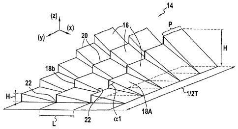
The security element 12 includes an array 14 of lines 16 in relief.
Each line 16 includes at least one flank 18 defining an angle of inclination
al
with respect to a direction normal to the plane of the array 14 (this
direction is
shown schematically by an axis Z of the cartesian benchmark [X, Y, Z]
indicated
in the figures).
In the example illustrated in Figures 1 through 4, each line 16 has a
generally rectilinear form and the lines 16 of the array 14 are substantially
parallel to one another. Of course, in a variation not illustrated in the
figures, the
array can consist of a single line, in the shape of a spiral for example. In
this
case, the array consists of the plurality of turns of the spiral.
More particularly, the angle of inclination al of the flank 18 of at least
one line 16 of the array 14 varies gradually along this line 16 so as to form
in
reflected light an optical shading effect that changes depending on an angle
of
observation O of the security element 12.
CA 02761779 2011-11-10
An array 14 of contiguous parallel lines 16 is shown at an oblique
observation angle in Figures 2 and 3, illuminated by a light beam
perpendicular
to the array 14. A light source 13 generating the light beam is shown
schematically above the security element 12. Further, an eye 15 of a human
5 observer is shown schematically to the left of each of the Figures 2 and
3. The
angle of observation 0 with respect to the normal varies from one of the
figures
to the other from a value 01 (Figure 2) to 02 (Figure 3), where 02 is greater
than 01.
Thus we see on these figures that the reflection of the light on the
10 array 14 forms an optical shading effect illustrated schematically by a
variation
of a point density. This optical shading effect is determined by a variation
of the
angle of inclination al of the flanks 18 of the lines 16 of the array 14.
In this illustrated example, the angle of inclination al of the flank 18
of each line 16 varies sinusoidally from a minimum value near 70 in the end
zones Z1 of each line 16 to a maximum value in a middle zone Z2 of each line
16, near 900, passing through an intermediate zone Z3. In these figures, the
angles are shown to scale for reasons of clarity.
For an inclination near 90 , a light beam substantially parallel to the
normal direction Z is reflected in specular fashion in this direction, while
for an
inclination near 45 , the beam is reflected at substantially a right angle.
The eye 15 of a user, observing the security element 12 at an
orientation angle 01 substantially equal to 30 with respect to the normal,
thus
observes bright zones (particularly Z1) corresponding to zones of the array 14
inclined at 75 , dark zones (particularly Z2) corresponding to zones of the
array
inclined at 90 , and intermediate zones (particularly Z3) corresponding to
zones
of the array 14 inclined between 75 and 90 .
Thus, depending on the inclination of the flanks 18 of each line 16,
the light is reflected in different directions and not in a single favored
direction,
which creates an optical shading effect for the observer.
Further, this light distribution varies according to the angle of
observation 0 of the user. Thus, this optical shading effect changes when the
CA 02761779 2011-11-10
11
angle of observation varies from 01 (Figure 2) to 02 (Figure 3) and confers a
dynamic effect connected with this variation of reflected light distribution.
In this example, the angle of inclination al varies by predefined steps
P along the line 16. Preferably, the predefined step P is constant and has a
value greater than three microns. Possibly, as a variation, the predefined
step is
variable.
Further, preferably, the angle of inclination al of the flank 18 of the
line 16 varies periodically or pseudo-periodically. In this example, the
variation
of the angle of inclination is sinusoidal (Figures 2 and 3).
In a second variation of the first embodiment illustrated in Figure 15,
the variation of the angle can be spatially modulated in frequency so as to
make
information appear in the array 14. Such frequency modulation makes it
possible to insert into the array 14 a design modulated at high frequency on a
background modulated at low frequency. This design can be alphanumeric.
Thus it can be seen in this figure that the furrows 22 follow a
triangular trajectory comprising high-frequency portions and low-frequency
portions. The zone El comprising the high-frequency portions delimits in this
illustrated example the numeral two and the zone E2 comprises medium- and
low-frequency portions. Of course, the zone E2 can include a single spatial
modulation frequency and not several as illustrated in Figure 15.
Preferably, the period T of the variation is greater than 0.1
millimeters, preferably comprised between 0.5 and twenty millimeters. For
example, the step P corresponds to one-tenth of the period T.
Preferably, the width L of a line 16 is comprised between 10
micrometers and 2 millimeters, preferably between 100 micrometers and 1
millimeter. However, even though it is not visible in the figures, the width
can
also vary along each line 16. In addition, the line 16 has for example a
height H
comprised between 0 and 200 micrometers, preferably equal to 100
micrometers.
The different parameters can be optimized, for example by carrying
out simple printing tests until the desired effect is attained.
CA 02761779 2011-11-10
12
Preferably, each line 16 corresponds to another flank 18B arranged
such that the two flanks 18A and 18B join in a longitudinal ridge 20 of the
line
16. In addition the two facing flanks 18A and 18B of two contiguous lines 16
join
to form a furrow 22.
In the example illustrated in Figures 1 through 4, the other flank
18B has an inclination angle a2 that is constant along the line 16. More
precisely, in this example this angle of inclination a2 is zero with respect
to the
direction Z and the variation of the angle of inclination al is sinusoidal.
In this case, the ridge 20 of the line 16 has a height that is variable
along the longitudinal direction of the lines 16 as illustrated in Figures 5,
5A
and 5B. In this figure is shown the variation of the height of the ridge 20
along
one of the lines 16 of the array 14 of Figure 4. The variation of the height H
of
the ridge 20 follows that of the angle al along the line 16 and is therefore
sinusoidal. Further, in this case, the furrow 22 has a depth that is constant
along
the longitudinal direction of the lines 16. Possibly, the furrow 22 has a
depth that
is variable along the lines 16.
In a first variation illustrated by Figures 6, 6A and 6B, the variation
of the height H of the ridge 20 is triangular.
In a second variation illustrated in Figure 7, the angle of inclination
of the other flank 18B of the line 16 varies gradually along the line 16. For
example, the two facing flanks 18A, 18B of two contiguous lines 16 of the
array
14 join to form a furrow 22 with a depth that is constant along the lines 16.
The
variation of the angles of inclination al then follows a helical profile over
at least
one part.
In this case, the furrow 22 has a depth that is constant along the
longitudinal direction of the lines 16 as illustrated in Figures 8, 8A and 8B.
Thus in these figures two contiguous half-lines 15 are shown,
separated by a distance D equal to the width L of a line seen from above. It
is
seen that the trajectory of the furrow 22 along the lines has a generally
sinusoidal shape. However, as can be seen in cross section, the depth of the
furrow is constant along the lines 16. Possibly the trajectory of the furrow
can be
1
CA 02761779 2011-11-10
13
of generally triangular form in conformity with the illustration of Figures 9,
9A
and 9B.
Possibly, in variations not illustrated, one or more lines 16 of the
arr4ay 14 can have a generally curvilinear, circular, zigzag or spiral shape.
In the example described and according to the first embodiment, the
flanks 18A, 18B have a rectilinear cross section. However, it is possible to
provide flanks having cross sections of diverse and varied geometric shapes in
order to further enrich the optical effects produced by the array 14.
Thus are shown in Figures 16A through 16F, different forms of the
cross-sections of the flanks that can be contemplated. For example, the cross
section includes one or two convex (Figures 16D, 16E) or concave (Figures
16A, 16B) incidence breaks or a concave (Figure 16C) or convex (Figure 16F),
even parabolic or circular, curvilinear form. In this case, the angle of
inclination
of the flank 18 is defined as being an average angle of inclination.
In a second embodiment not illustrated by figures, the angle of
inclination of each flank 18A, 18B of a set of adjacent lines 16 of the array
14
varies gradually from one line to another of this set so as to form in
reflected
light an optical shading effect that changes according to an angle of
observation
of the security element.
In this case the array 14 in relief can also include the same features
of periodicity in the variation of the angle as in the first embodiment,
resulting
from a variable step corresponding this time to the width of a line.
Although this is not illustrated in the figures, in this second
embodiment, the array 14 can comprise only a single line, for example one
coiled into a spiral. In this case the angle varies from one turn of the
spiral to
another.
For example, the array includes parallel rectilinear lines. The angle
varies, not along the line but from one line to another, that is in a
direction
transverse to the lines of the array and not in a longitudinal direction as in
the
first embodiment described previously.
Of course, the features of the arrays according to the two
embodiments can be combined with one another. The variation of the angle of
CA 02761779 2011-11-10
14
the flanks of the lines of the array can be implemented longitudinally or
transversely to the lines of the array.
For example, in the first embodiment, the variations of inclination of
the flanks 18A, 18B having the same orientation of two contiguous lines 16 are
offset with respect to one another along the lines 16.
The formation of such a security element 12 according to one or the
other of the embodiments is for example carried out by intaglio printing or by
embossing on a suitable substrate, by means of an engraved plate.
For example, the security element 12 is made by inkless intaglio
printing, also called dry stamping technique.
In order to enrich the visual effects of this security, this dry stamping
will preferably be formed on a first layer of variable optical effect ink,
carried out
beforehand. Possibly, another layer of variable optical effect ink can be
applied
after formation of the dry stamping.
For example, the ink is selected from among an ink with an iridescent
optical effect, a variable optical effect ink, a magnetic variable optical
effect ink
and a liquid crystal ink and the array 14 is covered with this ink. Possibly
this ink
can be an ink that is invisible under white light and visible under
ultraviolet or
infrared radiation.
Adding an ink makes it possible to create a supplementary optical
effect coupling with the optical shading effect produced by the geometric
relief
of the array 14. These inks, known per se in the state of the art, include for
example pigments having a variable optical effect and changing color
depending on the angle of observation. Magnetic optically variable ink also
includes pigments that can be oriented within a magnetic field.
The ink includes for example, in addition to the pigments and the
solvents, polymerizable materials designed to be deposited on the value
document 10 using a printing process allowing the transfer of a thick layer of
ink
such as silkscreen printing, flexography and photoengraving.
In another variation, the array 14 is embossed in dry stamping on a
substrate made of bare paper or of plastic (polymer). The embossing is carried
out cold or hot (in the press). After this embossing step, another printing
step
CA 02761779 2015-03-13
consists of totally or partially covering the array 14 with ink. In this case,
the ink
used in this other printing step may or may not have variable optical effects.
The array 14 can be at least partially formed on a diffractive structure
such as a holographic patch or strip for example.
5 For the
purpose of protecting the security element 12 against
possible mechanical and/or physicochemical damage, an overprint varnish can
be applied for example according to one of the printing techniques selected
from among offset, silkscreen, flexography and photoengraving.
Figure 10 shows a map 24 of the relief in shades of gray of an
10 engraved
plate 26 allowing the manufacture of the security element 12 as
illustrated in Figures 1 through 4. Thus, with each gray shade of this map 26
corresponds a depth of engraving in the plate 26. As indicated by the
correlation
table of Figure 11, the scale of engraving depth of the plate 26 varies from 5
microns to 100 microns.
15 The
engraved plate 26 is shown in cross section in Figure 14. This
plate 26 includes an array 30 of sunken furrows 28 with a general shape that
is
complementary to the array 14 of lines 16 in relief of the security element
12.
Thus, the array of the engraved plate 26 has a relief that is inverse to that
of the
array 14 of the security element 12. In other words, a line 32 in relief of
the
array 30 of the plate 26 forms by printing a furrow 22 of the array 14 of the
printed security element 12 and a furrow 28 of the array 30 of the plate 26
forms
a line 16 in relief of the array 14.
Figures 12A through 12D illustrate the variation of the depth of a
furrow 28 of the plate 26 once engraved in conformity with the map 24, in
positions marked on the map 24 with the labels 12A, 12B, 12C and 12D. It is
thus seen that the variation in the depth of the furrow 28 is gradual.
The principal steps of a method of manufacturing the engraving plate
26 of Figure 14 will now be described. The method includes a step consisting
of engraving the plate 26 using an engraving tool controlled by a computer
according to a program defining the variation of the angle of inclination of
the
flank of each furrow 28 of the array 30 of the plate 26 in conformity with the
indications provided by the map 24.
CA 02761779 2011-11-10
16
The blank plate 26 is thus subjected to an engraving program using
this engraving tool controlled by a computer. The engraving step is carried
out
according to the depth data of the depth map 24. Preferably, the engraving
tool
is a laser engraving tool. As a variation, the tool is a precision mechanical
milling tool.
Digital engraving is controlled in all three spatial dimensions, which
allows easy control of the slope of the flanks with a resolution less than or
equal
to 5 microns.
Thus, the furrow 28 has preferably a stepped profile having individual
steps with a size less than or equal to 5 microns, as shown in Figure 13.
The invention takes advantage of the fact that thanks to such an
engraving process, it is possible to adjust with precision the inclination of
the
slopes or flanks of the furrows 28 of the array 30 of the plate 26.
The principal aspects of a security element 12 according to the
invention will now be described.
An observer wishes to authenticate the value document, that is the
banknote 10. For that purpose, he causes small-amplitude motions about the
direction Z normal to the banknote 10 so as to observe a changing optical
shading effect. Depending on the design of the variation in the flank angle of
each line, waves, moiré effects appear and propagate by degrees with the
motions caused by the observer, and this even for angles of observation near
the normal to the value document 10.
This impression of gradual propagation of the design is obtained in
particular thanks to the periodicity of the design in geometric relief formed
on
the array 14.
The observer then rapidly authenticates the value document.
Although the invention has been described by examples with
reference to appended figures, it is understood that many modifications can
occur to a person skilled in the art without thereby departing from the scope
of
the present invention.
Thus, the geometric parameters of the lines of the array such as in
particular the width, the length, the shape of the lines can change from one
line
CA 02761779 2015-03-13
. .
17
to another in the array, and even within the same line.