Note: Descriptions are shown in the official language in which they were submitted.
CA 02761847 2016-03-22
FACE SEALS FOR RESPIRATORS AND METHOD
OF MANUFACTURING RESPIRATORS
BACKGROUND
The subject matter herein relates generally to respiratory protection systems,
and more particularly, to face seals for respirators and a method of
manufacturing
respirators.
Numerous types of respirators for respiratory protection systems are known
that deliver breathing air and/or filtered breathing air to a user. Such
respirators have
different performance requirements depending on the circumstances in which the
devices are intended to be used. Examples of respirators include self
contained
breathing apparatus (SCBAs), air purification respirators (APRs), powered air
purification respirators (PAPRs), and the like that supply pressurized air or
that filter
or cleanse ambient air. Certification agencies set forth different
requirements, such as
fit factor requirements that correspond to assigned protection factors, for
different
types of respirators to allow users to select appropriate respirators or
respiratory
protection equipment for the environments they work in, with respect to
contaminants
and environmental conditions that warrant varying levels of protection.
Respirators typically include a face mask that should properly fit the face of
the wearer. The face mask is designed for a particular type of respirator. For
example, a face mask for a SCBA may be designed differently than a face mask
for an
APR or a PAPR. The seal for the face mask may be designed differently for the
SCBA than the APR, as the SCBA and APR have different tit factor requirements.
The materials of the face mask and/or the seal may be different depending on
the type
of respirator. As such, a user that must operate in different types of
environments to
perform different duties may need different face masks for each different
respirator.
It is costly for users to maintain multiple masks for each type of respirator
so that the
user can perform different duties. Additionally,
having multiple masks may
contribute to a logistical burden for the users and problems in inventory
control and
-1-
CA 02761847 2016-03-22
maintenance costs in that annual fit tests drive the cost of implementing and
supporting respiratory protection programs. Furthermore, having different
designs for
a family of respirator is costly in terms of design costs, tooling costs,
manufacturing
costs, and the like.
Seal of the face mask is an important feature affecting fit factor. One area
of
the face mask that is difficult to maintain seal with the user's face is under
the user's
chin. For example, movement of the user's mouth, such as during talking,
causes the
user's face to move relative to the seal, which may break the seal.
Additionally,
because it is inconvenient to attach a strap near the chin area of the mask,
the face
mask tends to move away from the user's chin area, such as when the user looks
down and the weight of the mask pulls the mask away from the user's face.
Additionally, some known face masks support canisters or other components that
tend
to pull the face mask away from the user's face.
Comfort in the fit of the face mask to the face also affects fit factor
because if
the face mask is not comfortable to wear the face mask will bother and
distract the
user or may cause painful "hotspots" on the wearers' faces, contributing to
undue
physiological burden. Additionally, the user may improperly don and tighten
the face
mask in an attempt to avoid such discomfort. Face masks are typically made in
only a
very limited number of shapes and sizes, intended for use with a wide variety
of facial
shapes and sizes in the user population. The varying anthropometric
accommodation
necessary to support the user population of human faces makes it difficult to
provide a
mask which will comfortably fit a large population of users.
A need remains for a respirator that is comfortable to wear. A need remains
for a respirator that has effective seal of the face mask to the user's face.
A need
remains for a respirator that is cost effective. A need remains for a facemask
with a
face seal that meets the requirements for different applications, such as SCBA
APR,
PAPR and other applications.
-2-
CA 02761847 2017-01-12
SUMMARY
Certain exemplary embodiments provide a respirator comprising: a mask
having a body extending between a front edge and a rear edge, the body
configured to
surround a chin, mouth, nose, and eyes of a user's face; a face seal extending
inward
from the body, the face seal having a first wall extending from the body and a
second
wall intersecting with the first wall at a sealing land, the sealing land
being configured
to contact the user's face to form a continuous circumferential seal, the face
seal being
folded over such that the first wall and the second wall both extend away from
the
sealing land in a common direction, wherein the second wall extends away from
the
sealing land to a free end, and wherein the free end of the second wall is
disengaged
from the mask body and the first wall when the sealing land is not in contact
with the
user's face, the free end of the second wall being configured to be pressed
into
engagement with the mask body as the sealing land is contacted with the user's
face;
and a chin cup extending from the first wall of the face seal, the chin cup
configured
to receive the chin of the user's face therein.
Other exemplary embodiments provide a face seal for a respirator mask, the
face seal comprising: a first wall extending inward from the mask to an end of
the first
wall; a chin cup extending forward from the first wall, the chin cup
configured to
receive the chin of a user's face therein; a sealing land at the end of the
first wall, the
sealing land being configured to surround a chin, mouth, nose, and eyes of the
user's
face and to contact the user's face to form a continuous circumferential seal
against
the user's face, the sealing land having a front end and a rear end where the
front end
is positioned forward of the rear end on the user's face; and a second wall
extending
outward from the sealing land to a free end of the second wall, wherein the
free end of
the second wall is disengaged from the mask and the first wall when the
sealing land
is not in contact with the user's face, the free end of the second wall being
configured
to be pressed into engagement with the mask as the sealing land is contacted
with the
user's face; wherein the first wall, sealing land, and second wall are
integrally formed
and define a U-shaped face seal configured to seal against the user's face.
-3-
CA 02761847 2017-01-12
Yet other exemplary embodiments provide a method of manufacturing a
respirator, the method comprising: forming a mask body configured to be worn
by a
user, the mask body configured to surround a chin, mouth, nose, and eyes of
the user's
face; positioning a face seal inward of the mask body, the face seal having a
first wall,
a second wall, a sealing land between the first and second walls, and a chin
cup
extending from the first wall, the chin cup configured to receive the chin of
the user's
face therein, the second wall extending from the sealing land to a free end of
the
second wall, the face seal being folded over to define a bulbous shape adapted
for
engaging the user's face; and securing an end of the first wall to the mask
body and
allowing the free end of the second wall to be free from the mask body,
wherein the
free end of the second wall is configured to engage the mask body when the
mask is
worn by the user such that the face seal is supported at two different points
along the
mask body.
BRIEF DESCRIPTION
In one embodiment, a respirator is provided that includes a mask having a
body extending between a front edge and a rear edge, and a face seal extending
inward from the body. The face seal has a first wall extending from the body
and a
second wall intersecting with the first wall at a sealing land. The sealing
land is
configured to contact a user's face to form a continuous circumferential seal.
The
face seal is folded over such that the first wall and the second wall both
extend away
from the sealing land in a common direction.
Optionally, the face seal may be U-shaped having an open side and a closed
side, with the open side being positioned outward with respect to the closed
side. The
-3 a-
CA 02761847 2016-03-22
face seal may be cantilevered from the body with the first wall extending
inward from
the body to the sealing land and with the second wall extending from the
sealing land
outward toward the body. The first and second walls may be spaced apart from
one
another to form a seal cavity generally bounded by the first and second walls,
the
sealing land and the body. Optionally, the face seal may be configured to be
deformed
when sealing against the face. The sealing land may be oriented generally
parallel to
the body when sealing against the face, the first wall may extend from a front
end of
the sealing land toward the body and the second wall may extend from a rear
end of
the sealing land toward the body. Optionally, the respirator may include a
chin cup
extending from at least one of the body and the face seal, where the chin cup
has a
bottom configured to extend under the chin of the user. The face seal may
extend
inward from the bottom of the chin cup. The face seal may be rolled upward to
form
a lip between the chin cup and the face seal, with the interface between the
chin cup
and the face seal being adapted to capture the chin therein. The face seal may
be
cantilevered from the body such that the second wall is free from the body.
The
second wall may be configured to be pressed against the body when the face
seal
engages the user's face such that the sealing land is supported by both the
first and
second walls.
In another embodiment, a face seal for a respirator mask is provided that
includes a first wall extending inward from the mask, a sealing land, and a
second
wall extending outward from the sealing land. The sealing land is configured
to
contact a user's face to form a continuous circumferential seal against the
user's face.
The sealing land has a front end and a rear end where the front end is
positioned
forward of the rear end on the user's face. The first wall, sealing land and
second
wall are integrally formed and define a U-shaped face seal configured to seal
against
the user's face.
In another embodiment, a method of manufacturing a respirator is provided
that includes the steps of forming a mask body configured to be worn by a user
and
positioning a face seal inward of the mask body. The face seal has a first end
and a
second end and a sealing land between the first and second ends. The face seal
is
-4-
CA 02761847 2016-03-22
folded over to define a bulbous shape adapted for engaging the user's face.
The
method also includes the step of securing the first end to the mask body and
allowing
the second end to be free from the mask body. The second end is configured to
engage the mask body when the mask is worn by the user such that the face seal
is
supported at two different points along the mask body. Optionally, the method
may
include the steps of providing a chin cup having a bottom configured to extend
along
a bottom of the user's chin and securing the chin cup to the face seal such
that the
sealing land is positioned inward with respect to the bottom of the chin cup.
BRIEF DESCRIPTION OF THE DRAWINGS
Figure 1 is a perspective view of a respirator formed in accordance with an
exemplary embodiment.
Figure 2 is a perspective view of an alternative respirator formed in
accordance with an alternative embodiment.
Figure 3 is an isometric view of a portion of the mask showing a face seal for
either of the respirators shown in Figures 1 and 2.
Figure 4 is a cross sectional view of the face seal shown in Figure 3.
Figure 5 is another cross sectional view of the face seal shown in Figure 3.
Figure 6 illustrates a portion of the respirator as the respirator is worn by
a
user.
DETAILED DESCRIPTION
Figure 1 is a perspective view of a respirator 10 formed in accordance with an
exemplary embodiment. The respirator 10 includes a mask 12 holding a lens 14
and
an air purifying cartridge 16. The mask 12 is adapted to be secured to a
user's face by
a head harness 18. The respirator is adapted to provide breathing gas to the
user
and/or to filter breathing air for the user, which includes air which has been
filtered or
otherwise treated so that airborne contaminants are removed therefrom. While
the
-5-
CA 02761847 2016-03-22
mask described herein is a full facemask (e.g., constructed to cover the eyes
as well as
the mouth and nose), it should be understood that the mask which embodies the
subject matter herein may alternatively be a half facemask (e.g., constructed
to cover
the mouth and nose but not the eyes) or a quarter mask (e.g., constructed to
cover the
nose and mouth but not extend under the chin), or the mask may be another type
of
face covering. In addition, while the mask 12 described in connection with the
preferred embodiment is constructed for attachment of air purifying cartridges
to
serve as a respirator, it should be understood that the mask 12 may
alternatively be
constructed for attachment of hoses for delivering oxygen or other breathable
gas, as
well as adapters to accept hoses, filters and/or regulators specific to
particular duties
or to be used in particular environments.
The mask 12 covers the eyes, nose and mouth of a person for protecting the
person from airborne contaminants by means of the air purifying cartridges or
filters
16. While the mask 12 is shown to have one air purifying cartridge 16
centrally
located in front of the user's mouth, it should be understood that the mask 12
could be
provided with any number of cartridges 16 and the cartridges 16 may be
positioned at
any suitable location. Various types of cartridges 16 (some containing gas
absorbents
and others containing mechanical filters and others containing both) may be
interchangeably attached to the mask 12. The mask 12 is fitted for a
particular use
with the type of cartridge 16 that is suitable for removing the particular
contaminants
in the environment at the time of use. In an exemplary embodiment, one or more
exhalation valves 20 are provided on the sides or at the front of the mask 12.
It
should also be understood that an exhalation valve may be used, and/or that a
separate
passageway for exhalation gases may not be required as the gas inlet could be
designed to handle the egress of exhalation gases on a part-time basis. In
some
embodiments, voice enhancement features may be provided on the sides or at the
front of the mask for allowing communication when wearing the mask.
The respirator 10 includes a nose cup 22 that surrounds the user's nose and
mouth. The nose cup 22 is positioned behind the lens 14. A flow path, such as
ductwork or another type of channel, is defined between the cartridge 16 and
the nose
-6-
CA 02761847 2016-03-22
cup 22 to deliver air to the user. Optionally, the nose cup 22 may be coupled
to the
lens 14. Alternatively, or additionally, the nose cup 22 may be coupled to the
mask 12.
In some embodiments, the respirator 10 may be provided without the nose cup
22.
The respirator 10 may be used for any of a number of applications, such as
self
contained breathing apparatus (SCBA) applications, air purification respirator
(APR)
applications, powered air purification respirator (PAPR) applications, and the
like. In
an exemplary embodiment, the same mask 12 may be used by a user for different
applications by interchanging the components attached to the mask 12 for
delivering
or expelling air. For example, by changing the type of cartridge or filter 16,
or by
attaching a hose to the mask 12, the user may be able to use the respirator 10
in a
different environment. The mask 12 provides a seal with the user's face that
meets
the requirements of more than one category of respirator for convertibility to
each of
the environments in which the user may embark.
Figure 2 is a perspective view of an alternative respirator 24 formed in
accordance with an alternative embodiment. The respirator 24 is similar to the
respirator 10 (shown in Figure 1). The respirator 24 includes the mask 12, the
lens 14
and the head harness 18. Rather than using a cartridge 16 (shown in Figure I)
as is
the case with the respirator 10, the respirator 24 includes a hose 26 for
delivering
oxygen or filtered breathing air. The hose 26 is connected to the mask 12
and/or the
lens 14. The other end of the hose may be attached to a powered air purifying
blower
with filters, to a remote mounted filter, and the like. The hose 26 may attach
to the
same port of the mask 12 and/or the lens 14 such that the hose 26 may be
interchangeable with the cartridge 16.
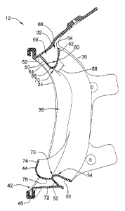
Figure 3 is an isometric view of a portion of the mask 12 showing a face seal
30 for the respirator 10 (shown in Figure 1). The lens 14, head harness 18
(both
shown in Figure 1) and other components have been removed for clarity. The
mask
12 and face seal 30 may be equally adapted for use with the respirator 24
(shown in
Figure 2).
-7-
CA 02761847 2016-03-22
The mask 12 includes a body 32 defining a perimeter of the mask 12. The
body 32 may be composed of a suitable soft pliable material, such as a rubber
material, for comfortably as well as sealing engagement with the face and/or
head of a
user. The body 32 may be used in conjunction with the face seal 30 to provide
additional sealing with the user. Optionally, the face seal 30 may be secured
to the
body 32 by being integrally formed with the body 32. For example, the face
seal 30
and the body 32 may be simultaneously molded with one another. Alternatively,
the
face seal 30 may be separately manufactured and coupled to the body 32. In
such
embodiment, the face seal 30 and the body 32 may be manufactured from
different
materials having different characteristics. For example, the body 32 may be
composed of a more rigid material, such as a plastic material, for defining a
donable
structure and the face seal 30 may be manufactured from a soft pliable
material to
accomplish the seal with the user's face.
The body 32 extends between a front edge 34 and a rear edge 36. The body 32
circumferentially surrounds a face receiving chamber 38 that is defined
between the
front and rear edges 34, 36. A plurality of mounting tabs 40 extend rearward
from the
rear edge 36. The head harness 18 is secured to the mounting tabs 40. Any
number
of mounting tabs 40 may be provided. An opening 42 is defined at the front
edge 34.
The lens 14 is mounted to the body 32 at the opening 42. The face seal 30
extends
inward from the body 32 proximate to the rear edge 36.
In an exemplary embodiment, the mask 12 includes a chin cup 44 that receives
the chin of the user. The chin cup 44 is coupled to the face seal 30. The chin
cup 44
may be additionally, or alternatively, coupled to the body 32.
Figure 4 is a cross sectional view of the face seal 30 with other portions of
the
mask 12 removed for clarity. The face seal 30 is configured to extend entirely
circumferentially around the user's face to completely seal the chamber 38.
The face
seal 30 is composed of different regions that engage different portions of the
user's
face, such as a forehead region, a temple region, a cheek region, and a chin
region,
each of which engage corresponding portions of the user's face.
-8-
CA 02761847 2016-03-22
The body 32 extends between the front edge 34 and the rear edge 36. A bezel
46 is provided at the front edge 34 and surrounds the opening 42. In an
exemplary
embodiment, the bezel 46 is a separate frame component attached to the body 32
and
includes a circumferential groove that receives the lens 14 (shown in Figure
I).
Alternatively, the body 32 may be folded over to form the bezel 46.
The face seal 30 includes a first wall 50 and a second wall 52 intersecting
with
the first wall 50 at a sealing land 54. The sealing land 54 is the portion of
the face
seal 30 that contacts the user's face to form the continuous circumferential
seal
around the user's face. The first wall 50, second wall 52, and sealing land 54
are
integrally formed with one another and define different portions of the face
seal 30
with the sealing land 54 spanning between the first and second walls 50, 52.
The first
wall 50 intersects with the sealing land 54 at a front end 58 thereof and the
second
wall 52 intersects with the sealing land 54 at a rear end 60 thereof. The
sealing land
54 is held away from the body 32 by the first and second walls 50, 52, and the
first
and second walls 50, 52 are spaced apart from one another to separately
support the
front end 58 and the rear end 60, respectively.
The sealing land 54 has a width 56 measured between the front end 58 and the
rear end 60, where the front end 58 is positioned forward of the rear end 60
on the
user's face. The width 56 may not be uniform or the same along different
portions of
the face seal 30. For example, the width 56 at the chin region may be
different than
the width 56 at the temple region. The width 56 may change as the mask 12 is
worn.
For example, the width 56 at the chin region may change as the user's mouth
opens
and closes. The width 56 may change as the user inhales or exhales, however
the
width 56 may be sufficient to prevent transfer of external air across the seal
barrier
under pressures due to breathing and to accommodate changes in pressure during
inhalation and exhalation to continuously maintain a seal. The air can only be
pulled
so far across the sealing land 54 (e.g. less than the entire width 56) with
inhalation
pressure to prevent the seal from being breached by external air.
-9-
CA 02761847 2016-03-22
The first wall 50 extends from the sealing land 54 toward the body 32 to a
first
end 62 of the face seal 30. The second wall 52 extends from the sealing land
54
toward the body 32 to a second end 64 of the face seal 30. In an exemplary
embodiment, the first end 62 is secured to the body 32, such as by being
integrally
formed with the body 32. The face seal 30 is cantilevered from the body 32
such that
the second wall 52 is free from the body 32 and not permanently mechanically
secured to the body 32. The second wall 52 is configured to be pressed against
the
body 32 and/or the first wall 50 when the face seal 30 engages the user's face
such
that the sealing land 54 is supported by both the first and second walls 50,
52 against
the body 32. For example, when the face seal 30 engages the user's face, the
face seal
30 is forced generally outward. The second wall 52 is likewise forced outward
until
the second wall 52 engages the body 32 and/or the first wall 50. Optionally,
the
second end 64, or a portion of the second wall 52 near the second end 64,
engages the
body 32 and/or the first wall 50. In alternative embodiments, both the first
and
second walls 50, 52 may be mechanically secured to the body 32, or only the
second
wall 52 may be mechanically secured to the body 32 while the first wall 50 is
free
from the body 32. The first and second walls 50, 52 operate as spring elements
to
support the sealing land 54. For example, the first and second walls 50, 52
may be
resiliently deflected when the mask 12 is donned such that the first and
second walls
50, 52 spring inward towards the user's face. As such, the sealing land 54 may
be
spring biased against the user's face to maintain a continuous circumferential
seal
around the user's face. The spring nature of the U-shape allows the mask 12 to
accommodate a wider range of face sizes and shapes.
The first and second walls 50, 52 may be moved independently with respect to
one another and with respect to the sealing land 54 and/or with respect to the
body 32.
As such, the sealing land 54 is capable of maintaining a seal against the
user's face
even if the first wall 50 and/or the second wall 52 are stretched or flexed
during
donning and/or wearing of the mask 12. The position of the sealing land 54
along the
face seal 30 may change as the mask 12 is donned, tightened or worn, however,
the
-10-
CA 02761847 2016-03-22
seal of the sealing land 54 is not disrupted because the first and second
walls 50, 52
are capable of moving independently and are spring biased against the user's
face.
In the illustrated embodiment, the face seal 30 is rolled or folded over such
that the face seal 30 has a bulbous shape, which in one embodiment is
generally U-
shaped, with the first and second walls 50, 52 surrounding a seal cavity 66.
The fold
defines an edge which is generally the inner-most portion of the face seal 30.
The
edge may be the portion of the face seal 30 that engages the user's face. The
first and
second walls 50, 52 are spaced apart from one another to form the seal cavity
66. The
seal cavity 66 is bounded by the first and second walls 50, 52, the sealing
land 54 and
the body 32. The first and second walls 50, 52 form the legs of the U-shaped
face seal
30 that extend between opposed sides, with one of the sides being an open side
68 and
the other side being a closed side 70. The open side 68 is positioned outward
of the
closed side 70, such as proximate to the body 32, and the closed side 70 is
positioned
inward of the open side 68 for engagement with the user's face. The closed
side 70
may represent the folded over portion of the facing seal 30. The closed side
70 may
be defined, at least in part, by the first wall 50, the second wall 52 and/or
the sealing
land 54. The closed side 70 is held away from the body 32 by the first and
second
walls 50, 52. Optionally, the closed side 70 may engage the user's face when
the
mask 12 is donned.
The chin cup 44 is provided near a bottom 72 of the body 32. Optionally, the
chin cup 44 may be coupled to the face seal 30 along the chin region and the
cheek
region. The chin cup 44 forms a pocket that receives the user's chin. The chin
cup 44
has a front 74 and a bottom 76. The transition between the front 74 and bottom
76 is
curved to accommodate the chin. A top of the front 74 may be angled slightly
rearward to follow the contour of the chin toward the lower lip and/or to
securely hold
the chin. The bottom 76 is spaced apart from the bottom 72 of the body 32. The
bottom 76 is secured to a portion of the face seal 30. For example, the chin
cup 44
may be integrally formed with the face seal 30 such that the bottom 76 of the
chin
cup 44 extends from the face seal 30.
-11 -
CA 02761847 2016-03-22
In an exemplary embodiment, a portion of the face seal 30 extends inward
with respect to the bottom 76. The face seal 30 is rolled upward above the
bottom 76
to form a lip 78 between the chin cup 44 and the face seal 30. The interface
between
the chin cup 44 and the face seal 30 is adapted to capture the chin therein.
The lip 78
is raised above the bottom 78 to actively capture the chin to prevent the chin
from
slipping out of the sealed area of the mask 12. The chin cup 44 and the lip 78
of the
face seal 30 constitute a ball detent for capturing the chin. For example, the
lip 78
cooperates with the chin cup 44 to form a detent feature, while the chin acts
as the
ball. Once the chin is seated in the chin cup 44, the lip 78 captures the chin
and jaw
and moves with the chin and jaw. The lip 78 does not allow the chin to slip
out of the
chin cup 44. In an exemplary embodiment, the face seal 30 faces forward toward
the
pocket of the chin cup 44 so that the face seal 30 provides a spring force
against the
chin and/or the jaw bone.
Figure 5 is another cross sectional view of a portion of the mask 12 showing
the face seal 30 taken generally along the cheek region of the face seal 30
and
illustrating the top portion of the mask 12 and face seal 30. Figure 5
illustrates the
first wall 50 of the face seal 30 extending from the body 32. The face seal 30
is
folded over such that the second wall 52 extends generally parallel to the
first wall 50.
The second end 64 of the second wall 52 is positioned near the rear edge 36.
The
second end 64 may be deflected toward the body 32 when the mask 12 is donned
and
the face seal 30 is deformed by the sealing engagement with the user's face.
Figure 6 is a partial cross sectional view illustrating a portion of the
respirator
worn by a user with the cartridge 16 (shown in Figure 1) removed for clarity
and
showing the face seal 30 sealing against the users face. The lens 14 is
coupled to the
bezel 46 and the body 32. The nose cup 22 surrounds the user's nose and mouth.
The
nose cup 22 includes a seal 80 that seals against the user's face. A portion
of the seal
80 engages the chin cup 44. Optionally, the nose cup may be integrally formed
with
the chin cup 44, the body 32 and/or the face seal 30.
-12-
CA 02761847 2016-03-22
When the mask is donned, the face seal 30 seals against the user's face. The
face seal 30 provides a continuous circumferential seal. The sealing land 54
is the
portion of the face seal 30 that engages the user's face. Figure 6 illustrates
the
forehead region of the sealing land 54 engaging the user's forehead and the
chin
region of the sealing land 54 engaging the user's chin. The user's chin is
received
within the pocket of the chin cup 44 and the chin sits in front of the lip 78.
The lip 78
is rolled up under the user's chin to capture the chin within the pocket. The
chin is
captured all around by the face seal 30 and the chin cup 44, such as under the
chin, in
front of the chin to under the lip, around the jaw and along the cheeks.
Because the
chin cup 44 is secured to the face seal 30, the chin cup 44 helps maintain the
integrity
of the seal between the sealing land 54 and the users face.
The folded over design of the face seal 30 generally forces the face seal 30
inward toward the user's face. The face seal 30 is pressed against the body 32
such
that both the first and second walls 50, 52 support the sealing land 54. When
the first
and second walls 50, 52 of the face seal 30 are compressed or deformed, such
as when
the sealing land 54 engages the user's face, the first and second walls 50, 52
act as
spring elements that provide a biasing force against the user's face. Such
biasing or
spring force maintains the seal against the user's face, which increases the
fit factor
and the integrity of the respirator 10. The sealing land 54 conforms to the
user's face
for better sealing, more comfort and higher fit factors.
The body 32 is attached to the head harness 18 (a portion of which is shown in
Figure 6). As a result, the body 32 may be deformed, such as by being
stretched as
the head harness 18 is tightened. However, with the face seal 30 acting as a
separate
structure from the body 32, the face seal 30 is not distorted or wrinkled when
head
harness 18 is tightened and/or when the body 32 is deformed. As a result, the
sealing
land 54 is not distorted or wrinkled, which may improve the fit factor and/or
security
of the seal.
-13-