Note: Descriptions are shown in the official language in which they were submitted.
CA 02761852 2011-11-14
WO 2010/133476 PCT/EP2010/056422
1
METHOD FOR OPERATING A REGENERATIVE HEATER
Technical Field
[0001] The present invention generally relates to a method for operating a
regenerative heater, such as a hot blast stove of a blast furnace. More
particularly,
the present invention relates to an improved heating cycle of such a
regenerative
heater.
Background Art
[0002] Blast furnaces are generally fed with hot blast air received from a
regenerative heater such as a hot stove or a pebble heater. Such a
regenerative
heater generally comprises a first column and a second column, fluidly
connected
at the top by a cupola. A burner is arranged in the lower portion of the first
column
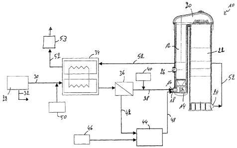
for burning a fuel and an oxidizing gas. The hot flue gasses created by the
burning
rise through the first column towards the cupola where they are directed into
the
second column. The second column is filled with checker bricks for absorbing
heat
from the hot flue gasses. The flue gasses then exit the second column via an
opening in the lower portion of the second column. After the heating cycle,
the
regenerative heater is switched to a blowing cycle wherein cold air is
generally fed
into the regenerative heater through the opening in the lower portion of the
second
column. As the cold air flows through the second column filled with hot
checker
bricks, heat is transferred from the checker bricks to the cold air, thereby
heating
up the air. At the top of the second column, the hot air then flows into the
first
column via the cupola. The hot air finally exits the first column via a blast
opening
arranged above the burner. The hot air is then fed as hot blast air to the
blast
furnace.
[0003] Such regenerative heaters and their operation are well known to the
skilled person and are generally used to heat blast air to a temperature of up
to
about 1250 C for injection into the blast furnace. In recent years, the used
of top
gas recirculation installations has come into the limelight in order to reduce
CO2
emissions into the atmosphere. Such top gas recirculation installations
recover top
gas from the top of the blast furnace and feed the recovered top gas through a
recycling process before injecting it back into the blast furnace. The
recycling
CA 02761852 2016-09-27
H8312471CA
2
process comprises an initial cleaning of the top gas to remove e.g. dust
particles,
before the top gas is subjected to a CO2 removal. The top gas is fed through a
CO2 removal unit in which CO2 is removed from the top gas, generally by
pressure
swing adsorption (PSA) or vacuum pressure swing adsorption (VPSA). The CO2
removal unit produces two streams of gas: a CO2 rich tail gas and a CO rich
process gas. The CO2 rich tail gas is generally fed through a cryogenic unit
to
separate pure CO2 out of the CO2 rich tail gas. The pure CO2 is subsequently
generally pumped into the ground for storage. The CO rich process gas may be
heated and fed back into the blast furnace as reducing gas.
[0004] The heating of the CO rich process gas may be carried out in
regenerative heaters. The replacement of cold blast air with CO rich process
gas,
i.e. a reducing gas, however has implications for the operation of the
regenerative
heaters. Indeed, the oxidizing gas fed to the regenerative heater during the
heating cycle is not compatible with the reducing gas fed through the
regenerative
heaters during the blowing cycle. In order to avoid that oxidizing gas is in
the
regenerative heater when the reducing gas is fed through, it may be suggested
to
carry out a purging of the regenerative heater before the blowing cycle is
started.
Purging the regenerative heater with at least three times its volume however
is
expensive, time consuming and unnecessarily reduced the temperature of the
checker bricks.
Technical Problem
[0005] It is thus an object of the present invention to provide an improved
method for operating a regenerative heater, wherein the method allows safely
heating a reducing gas in the regenerative heater. This object is achieved by
a
method as described below.
General Description of the Invention
[0006] The present invention proposes a method for operating a regenerative
heater, in particular a hot blast stove of a blast furnace, the regenerative
heater
comprising a first chamber and a second chamber, the first chamber having a
burner arranged therein, the second chamber comprising heat storage means.
Such a method comprises a heating cycle wherein fuel and oxidizing gas are fed
to the burner of the first chamber and allowed to burn and wherein hot flue
gasses
CA 02761852 2011-11-14
WO 2010/133476 PCT/EP2010/056422
3
are led through the second chamber to heat the heat storage means; and a
blowing cycle wherein a process gas is fed through the second chamber to pick
up
heat from the heat storage means. According to an important aspect of the
present
invention, the heating cycle comprises the steps of feeding a first stream of
fuel to
the burner of the regenerative heater; feeding a second stream of fuel to a
pre-
combustion chamber; feeding oxygen to the pre-combustion chamber; allowing the
second stream of fuel and the oxygen to interact so as to form oxidizing gas,
preferably at high temperature; and feeding the oxidizing gas to the burner of
the
regenerative heater. At the end of the heating cycle, the supply of oxygen to
the
pre-combustion chamber is discontinued, while further feeding the second
stream
of fuel to the pre-combustion chamber and further feeding the first stream of
fuel to
the burner.
[0007] As the second stream of fuel continues to be fed into the pre-
combustion
chamber, the second stream of fuel reacts with the oxygen still present in the
pre-
combustion chamber to form the oxidizing gas. Additionally, any oxidizing gas
still
present in the pre-combustion chamber or the feedline between the pre-
combustion chamber and the burner is pushed towards the burner of the
regenerative heater, where the oxidizing gas is still being burnt by the first
stream
of fuel. As a consequence, the amount of oxygen in the system is gradually
reduced until the system is essentially free from oxygen, i.e. there is no
more
oxygen in the pre-combustion chamber, the feedline or the burner. As no
further
oxygen is fed to the system, the oxygen is indeed being consumed from both
ends, thereby leading to a rapid reduction in the oxygen concentration. No
oxygen
is pushed through the first or second chambers of the regenerative heater,
thereby
keeping the latter essentially free from oxygen. This allows to safely feed
reducing
gas through the regenerative heater during the blowing stage, without however
having to purge the regenerative heater before each blowing cycle. It should
be
noted however that in the rest of the regenerative heater, a minimal amount of
oxygen may be present because of a slightly over-stoichiometric burning of the
second stream of fuel in the pre-combustion chamber. One important advantage
of
the above method is that the regenerative heater may be used for conventional
use with cold blast air and for use with reducing gas, without having to
modify the
structure of the regenerative heater.
CA 02761852 2011-11-14
WO 2010/133476 PCT/EP2010/056422
4
[0008] Preferably, the second stream of fuel is fed to the pre-combustion
chamber until the oxygen in the pre-combustion chamber, in the burner and in a
feed line between the pre-combustion chamber and the burner is consumed. In
other words, the second stream of fuel is fed to the pre-combustion chamber
until
the burner no longer receives oxidizing gas, but the second stream of fuel.
[0009] In the context of the present invention, the oxygen may be considered
to
be essentially consumed if an oxygen concentration in the rest of the
regenerative
heater is less than 1%.
[0010] Once the oxygen is essentially consumed, the supply of fuel to the pre-
combustion chamber and to the burner may be discontinued. It should however
not be excluded that the supply of fuel is discontinued some time after the
oxygen
is essentially consumed.
[0011] Advantageously, at the beginning of the blowing cycle, the regenerative
heater is pressurized and at the beginning of the heating cycle, the
regenerative
heater is depressurized. Preferably, process gas, i.e. reducing gas, is
transferred
from the regenerative heater to be de-pressurized to the regenerative heater
to be
pressurized.
[0012] The process gas is advantageously a CO rich process gas received from
a CO2 removal unit, which has a major part of its CO2 content removed. If the
CO2
removal unit is a (V)PSA unit with cryogenic unit, the process gas is free
from CO2,
whereas if the CO2 removal unit is a (V)PSA unit without cryogenic unit, the
process gas has reduced CO2 content. The fuel is advantageously a CO2 rich
tail
gas received from a CO2 removal unit. Using the CO2 rich tail gas from a CO2
removal unit as fuel for the burner of the regenerative heater allows for a by-
product of the CO2 removal unit to be used in a cost effective manner. Indeed,
this
tail gas contains mainly CO2, which is used for heating the regenerative
burner.
Although the gas exiting the regenerative burner during the heating cycle may
contain some CO, it is mainly composed of CO2 which leads to a more cost
effective use of the subsequent cryogenic unit.
[0013] At the beginning of the heating cycle, the CO in the regenerative
heater is
pushed out of the regenerative heater by the hot flue gasses as CO containing
off
gas. Indeed, after the blowing cycle, CO is present in the regenerative
heater.
CA 02761852 2011-11-14
WO 2010/133476 PCT/EP2010/056422
When the burner is started, this CO is pushed out of the regenerative heater
through the opening in the lower portion of the second chamber.
[0014] Preferably the CO containing off gas is treated to remove its CO
content
before the off gas is evacuated. According to a first embodiment, the CO
containing off gas may be fed to a cryogenic plant to remove the CO content
and
ensure that only CO2 is pumped into the ground. Preferably however, the amount
of CO in the CO containing off gas is measured and, as long as a presence of
CO
can be detected in the off gas, the latter is recycled.
[0015] According to a second embodiment, the CO containing off gas is fed back
into a stream of tail gas, thereby allowing the CO to be reused in the tail
gas in the
pre-combustion chamber. According to a third embodiment, the CO containing off
gas is fed, via a booster unit, back to a CO2 removal unit, where the CO is
then
redirected into the process gas for heating. According to a fourth embodiment,
the
CO containing off gas is fed into a gas holder, from where it may used
elsewhere
in the steel making plant. The CO containing off gas may indeed be used as
high
calorific value gas to be fed into the first stream of fuel.
[0016] The fuel may according to the present invention be a tail gas rich in
CO2,
i.e. the tail gas coming from the CO2 removal unit.
[0017] Advantageously, the tail gas is heated in a heat exchanger before it is
divided into the first stream of fuel and the second stream of fuel. The hot
flue
gasses escaping the second chamber may be fed through the heat exchanger for
transferring heat to the tail gas.
[0018] High calorific value gas may be fed into the first stream of fuel to
improve
the burning of the fuel in the burner of the regenerative heater. High
calorific value
gas may also be fed into the tail gas before it is fed into the heat exchanger
in
order to improve the ignition characteristics of the tail gas in the pre-
combustion
chamber.
Brief Description of the Drawings
[0019] Preferred embodiments of the invention will now be described, by way of
example, with reference to the accompanying drawings, in which:
CA 02761852 2011-11-14
WO 2010/133476 PCT/EP2010/056422
6
Fig. 1 is a flow diagram showing the heating cycle of the method according to
a
first embodiment of the invention;
Fig. 2 is a flow diagram showing the heating cycle of the method according to
a
second embodiment of the invention;
Fig. 3 is a flow diagram showing the heating cycle of the method according to
a
third embodiment of the invention; and
Fig. 4 is a flow diagram showing the heating cycle of the method according to
a
fourth embodiment of the invention.
Description of Preferred Embodiments
[0020] Figure 1 shows a flow diagram of the heating cycle of the method for
operating a regenerative heater according to a first embodiment of the present
invention. Figure 1 also shows a schematic view of a regenerative heater 10 in
the
form of a hot blast stove.
[0021] Such a regenerative heater 10 generally comprises a first chamber 12
with a burner 14 arranged therein. During the heating cycle, fuel and
oxidizing gas
is fed to the burner 14 via two gas inlets 16, 18. The fuel and oxidizing gas
are
ignited and their combustion creates hot flue gasses, which ascend into a
cupola
20. The cupola 20 deviates the hot flue gasses and feeds them into a second
chamber 22 comprising a series of heat storage means, generally in the form of
checker bricks (not shown). The hot flue gasses finally exit the regenerative
heater
through an opening 24 in the lower portion of the second chamber 22.
[0022] During the subsequent blowing cycle, process gas is blown into the
second chamber 22 through the opening 24 in the lower portion of the second
chamber 22. As the process gas passes through the checker bricks, heat is
transferred from the checker bricks to the process gas. At the top of the
second
chamber 22 the hot process gas is fed, via the cupola 20, into the first
chamber
12. The hot process gas exits the regenerative heater 10 through a process gas
outlet 26 and is fed into the blast furnace (not shown).
[0023] The structure of a regenerative heater 10 itself is generally well
known to
the skilled person and will therefore not be described in closer detail
herein.
CA 2761852 2017-03-01
H8312471CA
7
[0024] In blast furnace installations with top gas recycling, the top gas
recovered
from the blast furnace is cleaned and passed through a CO2 removal unit 28
wherein CO2 is removed from the top gas, generally by pressure swing
adsorption
(PSA) or vacuum pressure swing adsorption (VPSA). A (V)PSA installation
divides
the cleaned top gas into two separate gas streams: a CO2 rich tail gas and a
CO
rich process gas. The CO rich tail gas is heated by feeding it through a
regenerative heater before it is injected back into the blast furnace.
According to
the present invention, the tail gas 30, which is rich in CO2 (but still
contains CO), is
enriched and used to fuel the burner 14 of the regenerative heater 10 during
the
heating cycle, whereas the CO rich process gas 32 is used as reducing gas.
[0025] The CO2 rich tail gas coming from the CO2 removal unit 28 is first fed
through a heat exchanger 34 to heat the tail gas 30 before it is led to a
distribution
point 36. At the distribution point 36 the heated tail gas is split into two
separate
streams. A first stream 38 of the tail gas is fed as fuel to the burner 14
after a high
calorific value gas 40 is added.
[0026] A second stream 42 of the tail gas is fed to a pre-combustion chamber
44
into which oxygen 46 is further fed. In the pre-combustion chamber 44, the
second
stream 42 of the tail gas and the oxygen 46 interact so as to form oxidizing
gas 48
at high temperature, which is then fed as oxidizing gas to the burner 14. Such
oxidizing gas 48 may e.g. have a composition of mainly about 79% CO2 and
mainly about 21% 02 (some impurities may be present). The first stream 38 of
the
tail gas and the oxidizing gas 48 are burnt in the first chamber 12 of the
regenerative heater 10 and form the hot flue gasses necessary for heating the
checker bricks in the second chamber 22. The hot flue gasses then exit the
second chamber 22 through opening 24 and are preferably fed through the heat
exchanger 34 to transfer heat from the hot flue gasses to the tail gas also
passing
through the heat exchanger 30. In order to facilitate ignition of the mixture
of tail
gas and oxygen in the pre-combustion chamber 44, high calorific value gas 50
may further be added to the tail gas before passing it through the heat
exchanger
34.
[0027] As, in the blowing cycle, a reducing gas rich in CO is fed through the
regenerative heater 10, it is important that the latter is free from oxidizing
gas. The
CA 02761852 2011-11-14
WO 2010/133476 PCT/EP2010/056422
8
reducing gas and oxidizing gas would otherwise form a dangerous mixture that
could ignite and damage the regenerative heater 10.
[0028] In order to ensure that no oxidizing gas is present during the blowing
cycle, the present invention suggests that, at the end of the heating cycle,
first the
oxygen supply to the pre-combustion chamber 44 is stopped. Consequently, no
more oxygen is fed into the system. However, oxygen is still present in the
pre-
combustion chamber 44, in the burner 14 and in the piping therebetween. It is
therefore suggested to continue feeding the second stream 42 of the tail gas
to the
pre-combustion chamber 44, thereby continuing to consume oxygen in the pre-
combustion chamber 44. Furthermore, the first stream 38 of the tail gas is
also still
fed to the burner 14, thereby continuing to consume oxygen in the burner 14.
[0029] While the fuel and oxidizing gas continue to burn in the burner 14, the
second stream 42 of tail gas fed into the pre-combustion chamber 44 forces the
oxidizing gas 48 further towards the burner 14. When all the oxidizing gas is
gone
and the second stream 42 of tail gas meets the first stream 38 of tail gas in
the
burner 14, the combustion stops because of the absence in oxidizing gas 48.
[0030] As no more oxidizing gas is present, the blowing cycle can begin
safely,
even if the gas fed through the regenerative heater 10 during the blowing
cycle is
a reducing gas, e.g. process gas rich in CO. There is almost no oxygen in the
regenerative heater 10 that the process gas could react with. It is important
to note
that, with the present method, it is not necessary to purge the regenerative
heater
when switching from the heating cycle to the blowing cycle. It is also
important
to note that, with the present method, it is not necessary to purge the
regenerative
heater 10 when switching from the blowing cycle to the heating cycle.
[0031] At the beginning of the heating cycle, the regenerative heater still
contains CO rich process gas. The flue gasses coming from the burner 14 push
the CO in the regenerative heater as CO containing off gas 52 out of the
regenerative heater through the opening 24 in the lower portion of the second
chamber 22. As the CO containing off gas 52 is hot, it is preferably fed
through the
heat exchanger 34 to transfer heat from the CO containing off gas 52 to the
tail
gas 30. After passing through the heat exchanger 34, the CO containing off gas
52
CA 02761852 2016-09-27
H8312471CA
9
is, according to the embodiment of Figure 1 fed to a cryogenic unit 53 for
removing
CO which may then be used elsewhere.
[0032] Figure 2 shows a flow diagram of the heating cycle of the method for
operating a regenerative heater according to a second embodiment of the
present
invention. This flow diagram is very similar to the one shown in Figure 1 and
will
therefore not be described in detail. In this second embodiment, the amount of
CO
in the CO containing off gas 52 is measured and, as long as a presence of CO
can
be detected in the CO containing off gas 52, the CO containing off gas 52 is
fed as
recycled CO containing gas 54 back into the tail gas 30.
[0033] Figure 3 shows a flow diagram of the heating cycle of the method for
operating a regenerative heater according to a third embodiment of the present
invention. This flow diagram is very similar to the one shown in Figure 1 and
will
therefore not be described in detail. In this third embodiment, the amount of
CO in
the CO containing off gas 52 is measured and, as long as a presence of CO can
be detected in the CO containing off gas 52, the CO containing off gas 52 is
fed as
recycled CO containing gas 54 into a gas holder 56. The recycled CO containing
gas 54 from the gas holder 56 may be used elsewhere in the steel making plant.
As shown in Figure 3, it may e.g. be fed as high calorific value gas into the
first
stream of tail gas 38.
[0034] Figure 4 shows a flow diagram of the heating cycle of the method for
operating a regenerative heater according to a fourth embodiment of the
present
invention. This flow diagram is very similar to the one shown in Figure 1 and
will
therefore not be described in detail. In this fourth embodiment, the amount of
CO
in the CO containing off gas 52 is measured and, as long as a presence of CO
can
be detected in the CO containing off gas 52, the CO containing off gas 52 is
fed
into the CO2 removing unit 28 via a booster unit 58. In the CO2 removing unit
28
the CO from the CO containing off gas 52 if fed into the process gas 32.
Legend of Reference Numbers:
hot blast stove 18 gas inlet
12 first chamber 20 cupola
14 burner 22 second chamber
16 gas inlet 24 opening
CA 02761852 2011-11-14
WO 2010/133476
PCT/EP2010/056422
26 blast air outlet 44 pre-combustion chamber
28 CO2 removal unit 46 oxygen
30 tail gas 48 oxidizing gas
32 process gas 50 high calorific value gas
34 heat exchanger 52 CO containing off gas
36 distribution point 54 recycled CO containing gas
38 first stream of tail gas 56 gas holder
40 high calorific value gas 58 booster unit
42 second stream of tail gas