Note: Descriptions are shown in the official language in which they were submitted.
CA 02761942 2016-07-04
SHOCK ABSORBING ASSEMBLY FOR GAS IGNITER
[0001] BACKGROUND
[0002] Exemplary embodiments herein generally relate to gas igniters. More
particularly, the present disclosure is directed to a shock absorbing assembly
for a gas
igniter.
[0003] It is well known that a gas igniter can be used to ignite a
flammable gas for
use in connection with all types of heating applications. Further, it is well
known that the
gas igniter must be supported relative to a support surface located in the
heating
apparatus so that the gas igniter is properly oriented relative to the gas
flow. In order to
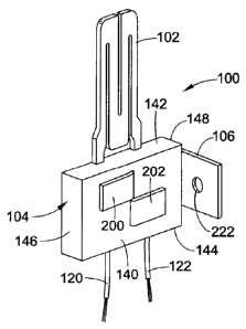
support the gas igniter, a mounting device or bracket is generally connected
to the gas
igniter. The mounting bracket can be securely fastened to the gas igniter
without
damaging the gas igniter and can be securely fastened to the support surface
in the
heating apparatus. Further, the mounting bracket must be capable of
withstanding the
environments in which the gas igniter is to be used. In this respect, gas
igniters are
used to ignite a flammable gas which, in turn, is used to provide the heat for
the heating
apparatus. As a result, the gas igniter and mounting bracket are subjected to
high
temperatures produced by the burning gas. In addition, during the function of
igniting
the gas and the operation of the heating apparatus, the gas igniter and
mounting
bracket are subjected to vibrations. Due to the adverse conditions in which
the gas
igniter and bracket are used, it is common practice to produce the mounting
bracket
from a thin sheet metal corrosion resistant metal.
[0004] An example of a conventional gas igniter 50 is shown in FIG. 1. The
gas
igniter 50 includes an igniting or heating element 52, a bushing 54 and a
mounting
device or bracket 56. Lead wires 58 are electrically connected to the heating
element.
The bracket includes a U-shaped portion 60 dimensioned to securably receive
the
bushing 54. The bushing can include a surface artifact (not shown) that
projects from
the surface and is configured so as to mechanically engage an aperture (not
shown) in
1
CA 02761942 2011-11-14
WO 2010/132793
PCT/US2010/034941
the bracket 56. The bracket 56 further includes a flange portion 70 connected
to the U-
shaped portion 60. The flange portion 70 includes a pair of through apertures
72,74 by
which the bracket 56 is secured to the support surface of the heating
apparatus, thereby
also securing the gas igniter 50 to the support surface. The connection of the
bracket
56 to the bushing 54 is done manually to be effective.
[0005] While known mounting brackets for gas igniters, such as bracket 56
of FIG. 1,
are designed to adequately maintain the gas igniter in an operating position
relative to
the support surface of the heating apparatus, conventional brackets do not
sufficiently
withstand and absorb shock and vibrations produced by the heating apparatus
while
maintaining the proper orientation of the heating element of the gas igniter.
This, in
turn, reduces the life expectancy of the gas igniter. Further, the known
mounting
brackets are relatively expensive and require a number of formed sheet metal
components and a multitude of assembly operations. Thus, there is a commercial
need
for a mounting device or bracket to be used with a gas igniter which
sufficiently absorbs
shock, but involves use of less metal, has a lower cost and requires fewer
assembly
operations.
BRIEF DESCRIPTION
[0006] In accordance with one aspect, a gas igniter comprises a heating
element, a
bushing and a mounting bracket. The bushing is formed of a generally rigid
electrically
insulating material and supports the heating element. The bushing includes an
elongated slot extending through the bushing. The mounting bracket includes a
first
connecting portion and a second mounting portion. The first connecting portion
is
inserted through the elongated slot located on the bushing for connecting the
mounting
bracket to the bushing. The second mounting portion is configured to attach
the gas
igniter to an associated support surface.
[0007] In accordance with another aspect, a gas igniter comprises a heating
element
having rear poles, a bushing for supporting the heating element and a mounting
bracket. The bushing is rectangular shaped and is formed of a generally rigid
electrically insulating material. The bushing defines a first cavity and a
second cavity.
The first and second cavities are adapted to laterally receive and
electrically isolate the
2
CA 02761942 2011-11-14
WO 2010/132793
PCT/US2010/034941
rear poles of the heating element. The bushing includes a laterally = oriented
slot
extending through the bushing. The mounting bracket including a connecting
portion.
The connecting portion is inserted through the slot, an end section of the
connecting
portion being configured to engage the bushing for connecting the mounting
bracket to
the bushing.
[0008] In accordance with yet another aspect, a flat igniter comprises a
heating
element having rear poles, a bushing for supporting the heating element and a
mounting bracket. The bushing is rectangular shaped and is formed of a
generally rigid
electrically insulating material. The bushing defines a first cavity and a
second cavity
separated from the first cavity by a laterally extending wall. The first and
second
cavities are adapted to laterally receive and electrically isolate the rear
poles of the
heating element. An elongated slot is located on the wall and extends through
the
bushing. High temperature ceramic adhesive is located in the first and second
cavities
for fixedly securing the rear poles of the heating element in the bushing. The
mounting
bracket includes a connecting portion and a mounting portion. The connecting
portion
is inserted through the elongated slot. An end section of the connecting
portion
extending through the slot includes at least one bendable flap configured to
engage the
bushing for firmly connecting the mounting bracket to the bushing. The
mounting
portion is configured to attach the flat igniter to an associated support
surface.
BRIEF DESCRIPTION OF THE DRAWINGS
[0009] FIG. 1 is a perspective view of a known gas igniter.
[0010] FIG. 2 is a perspective view of an exemplary gas igniter according
to the
present disclosure, the exemplary gas igniter including a heating element, a
bushing for
supporting the heating element and a mounting bracket.
[0011] FIG. 3 is a front view of the gas igniter of FIG. 2.
[0012] FIGS. 4-6 illustrate a first partial assembly of the gas igniter of
FIGS. 2 and 3,
particularly the connection of the heating element to the bushing.
[0013] FIG. 7-9 illustrate a second partial assembly of the gas igniter of
FIGS. 2 and
3, particularly the connection of the mounting bracket to the bushing
3
CA 02761942 2011-11-14
WO 2010/132793
PCT/US2010/034941
[0014] FIG. 10 is a simplified schematic view of a heating apparatus having
the gas
igniter of FIGS. 2 and 3 mounted to a support surface.
DETAILED DESCRIPTION
[0015] It should, of course, be understood that the description and
drawings herein
are merely illustrative and that various modifications and changes can be made
in the
structures disclosed without departing from the present disclosure. It will
also be
appreciated that the various identified components of the exemplary gas
igniter
disclosed herein are merely terms of art that may vary from one manufacturer
to
another and should not be deemed to limit the present disclosure. The present
disclosure is particularly applicable for use in connection with heating
applications.
However, the present disclosure has broader applications and may be used with
any
type of appliance and/or heating apparatus which utilizes a gas igniter.
[0016] Referring now to the drawings, wherein like numerals refer to like
parts
throughout the several views, FIGS. 2 and 3 illustrate an exemplary gas
igniter 100
according to the present disclosure. The gas igniter 100 is a hot surface flat
igniter
used to ignite a flammable gas for use in connection with all types of heating
appliances. The gas igniter 100 generally comprises a heating element 102, a
bushing
104 and a shock absorbing assembly or mounting bracket 106.
[0017] With reference to FIG. 4, the heating element 102 for use with the
flat igniter
100 includes a generally rectangular shaped coil 110 and rear poles or
terminals
112,114. The coil 110 extends outwardly from the bushing 104 which it is
secured to
and is formed of a high resistance heating material The rear poles 112,114 are
connected to respective input leads 120,122 to cause rapid heating of the coil
110. As
explained further below in connection with FIG. 10, these input leads 120,122
are
selectively and electrically interconnected to an electrical power source 126
through an
electrical power switch 128. As is known in the art, the heating element 102
of the gas
igniter 100 is heated to a desired temperature by passing an electrical
current through
the heating element, similar in principle to the electrical heating element
for a
conventional stove, for the purposes of igniting a flammable gas of a heating
appliance
300 (FIG. 10).
4
CA 02761942 2011-11-14
WO 2010/132793
PCT/US2010/034941
[0018] The bushing 104 is formed of a generally rigid electrically
insulating material
and supports the heating element 102. As shown in FIGS. 2, 4 and 5, the
bushing 104
is generally rectangular shaped and includes a base 140, sidewalls 142,144 and
end
walls 146,148. The sidewalls and the end walls extend outwardly from the base.
Located on sidewall 142 are a pair of spaced apart first notches or openings
160,162
dimensioned to receive the rear poles 112,114 of the heating element 102. A
pair of
spaced apart second notches or openings 164,166 are located on sidewall 144
and are
dimensioned to receive the input leads 120,122. The base together with the
opposed
sidewalls and opposed end walls define a first cavity 170 and a second cavity
172. The
first and second cavities 170,172 are adapted to laterally receive and
electrically isolate
the rear poles 112,114 of the heating element 102.
[0019] To electrically isolate the rear poles, the first and second
cavities 170,172 are
separated by a wall 180. In the depicted exemplary embodiment, the wall 180
extends
laterally between the sidewalls 142,144 to separate the first and second
cavities
170,172. The wall 180 includes a slot 182 which extends through the bushing
102. The
elongated slot extends laterally between the sidewalls 142,144 and is equally
spaced
from the end walls 146,148. Each end portion of the elongated slot 182 is
spaced from
one of the sidewalls of the bushing 104. As will be discussed in greater
detail below,
the slot is dimensioned to receive a connecting portion 190 of the mounting
bracket 106.
To secure fixedly secure the rear poles 112,114 of the heating element 102 in
the
bushing 104, an adhesive 184 is provided in the first and second cavities
170,172.
According to one aspect, the adhesive is high temperature ceramic cement;
although,
alternative adhesives are contemplated.
[0020] With reference now to FIGS. 7-9, the mounting bracket 106 supports
the
bushing 104 of the gas igniter 100 to a remote external support surface or
structure 304
(FIG. 10) so that the gas igniter 100 is in the proper position for efficient
ignition of the
flammable gas of a heating appliance. The mounting bracket 106 is capable of
withstanding high temperatures created by the burning gas. In addition,
because the
gas igniter 100 and bracket 106 are both subjected to intermittent vibrations,
the
mounting bracket 106 is generally rigid and capable of absorbing shock, while
maintaining the proper orientation of the heating element 102 of the gas
igniter 100.
CA 02761942 2011-11-14
WO 2010/132793
PCT/US2010/034941
Due to the adverse conditions in which the gas igniter 100 and mounting
bracket 106
are used, the mounting bracket is produced from a single sheet of shock
resistant,
corrosion resistant metal.
[0021] The mounting bracket 106 is generally U-shaped and includes the
connecting
portion 190, a mounting portion 192 and a base portion 194 which spans between
the
connecting and mounting portions. The connecting portion 190 is inserted
orthogonally
through the elongated slot 182 located on the wall 180 of the bushing 104.
According to
one aspect, an end section 198 of the connecting portion 190 that extends
through the
elongated slot 182 includes at least one tab or flap which can be folded or
bent towards
the base 140 of the bushing 104 for firmly connecting the mounting bracket to
the
bushing. In the depicted embodiment, the at least one flap include a first
flap 200 and a
second flap 202 which are folded in opposite directions toward the base 140.
As
shown, the first flap 200 is folded towards sidewall 142 and the second flap
is folded
towards sidewall 144. This attachment of the bracket 106 to the bushing 104
simplifies
the automation of the assembly. It should be appreciated that the first and
second flaps
200,202 are sufficiently sized to prevent the connecting portion 190 of the
bracket 106
from moving out of the elongated slot 182. For example, the combined length of
the
folded first and second tabs 200,202 is about one-half the length of the
bushing 104.
[0022] As depicted in FIGS. 4-6, to assemble the gas igniter 100, the rear
poles
112,114 of the heating element 102 are positioned in the first and second
cavities
170,172. The input leads 120,122 are connected to the rear poles. To firmly
secure the
heating element 102 to the bushing 104, the first and second cavities 170,172
are then
filled with the adhesive 184. As shown in FIGS. 7-9, the connecting portion
190 is
inserted through the slot 182 on the wall 180 until the end section 198
projects
outwardly from the base 140 of the bushing 104. The first and second tabs
200,202
located on the end section 198 are then folded in opposite directions against
the base
140. According to another exemplary embodiment, an adhesive passage (not
shown)
can be provided in the wall 180. This allows the adhesive 184 to flow between
the first
and second cavities 170,172. Prior to the adhesive hardening, the bracket 106
is
connected to the bushing 104 in the same manner described above. According to
this
6
CA 02761942 2011-11-14
WO 2010/132793
PCT/US2010/034941
aspect, the connecting portion 190 will pass through the adhesive 184 located
in the
passage, the adhesive further securing the mounting bracket 106 to the bushing
104.
[0023] The mounting portion 192 of the mounting bracket is configured to
attach the
gas igniter 100 to the associated support surface 304 (FIG. 10). According one
aspect
of the present disclosure, the mounting portion 192 includes spaced apart
mounting
apertures 220,222 by which the bracket 106 is secured to the associated
support
surface. For example, threaded ends of fasteners, such as bolts, can extend
through
the apertures 220,222 and corresponding apertures in the support (not shown)
and
threadably received in the threaded apertures of nuts (not shown). As is known
in the
art, the nuts and fasteners are tightened thereby securing the mounting
bracket 106 to
the support surface 304. In this way, the gas igniter 100 is directly secured
to the
support surface 304 of a heating device, which support surface can be the
burner tube
of the heating device 300 (FIG. 10).
[0024] Although a nut and bolt type of connection is described above, this
shall not
constitute a limitation on the mechanism that secures mounting bracket 106 of
the gas
igniter 100 to the support surface 304. For example, the apertures in the
support can
be a threaded aperture in which is threadably received the threaded ends of
the bolts.
The fasteners also can be a well known self-tapping screws that can be screwed
into
corresponding blind holes comprising the apertures in the support. Also the
support
surface can be configured with studs that extends outwardly from the support.
The
apertures 220,222 can be slotted and secured to the studs using any of a
number of
techniques known to those skilled in the art. Such examples are illustrative
of a few
techniques for securing the mounting portion 106 to the support surface 304
and thus
shall not be construed as limiting the different ways in which the gas igniter
100 can be
secured to the support surface.
[0025] With reference again to FIG. 7, the base portion 194 of the mounting
bracket
106 has an offset section 230 and an arcuate section 232. This offset section
230 is
connected to the an end of the connecting portion 190 so that a length of the
connecting
portion is less than a length of the mounting portion 192. The arcuate section
232 is
connected to an end of the mounting portion192. As indicated previously, to
secure the
bracket 106 to the bushing 104, the connecting portion is inserted through the
elongated
7
CA 02761942 2011-11-14
WO 2010/132793
PCT/US2010/034941
slot 182. The first and second tabs 200,202 are then folded onto the base 140
of the
bushing. Once secured, the offset section 230 of the base portion 194 together
with the
connecting portion 190 lifts the bushing 104 away from the mounting portion
192. In
other words, the bushing is spaced from the mounting portion by the arcuate
section
232. This allows the mounting portion 192 to be easily attached to the support
surface
via one of the exemplary manners described above. Further, because the gas
igniter
100 and mounting bracket 106 are both subjected to intermittent vibrations, by
spacing
the bushing 104 from the support surface via the arcuate section 232, at least
some of
the intermittent vibrations can be dampened by the arcuate section.
[0026] As indicated above, the bushing 104 is secured to the support
surface 304
and is configured to make the gas igniter 100 more resistant to external
loads, such as
external impact loads, occurring during manufacturing, shipping and handling
or during
installation of the heating device. In other words, a larger percentage of the
external
loads being applied to the gas igniter 100 during manufacturing, shipping and
handling
or during installation of the heating device, in particular external impact
loads, do not
cause a failure of the gas igniter 100 as compared to the loads causing
failures of
ignition devices that are secured to a support without a shock absorbing
assembly.
The external loads or external impact loads of particular interest to the
failure of the
heating element 102 of the gas igniter 100 illustrated in FIG. 1, are those
that can be
applied in one of the directions transverse to a longitudinal axis of the
heating element
102. The shock absorbent mounting bracket 106 is generally made of a material
having
a thickness and firmness sufficient to resist external impact loads applied to
the gas
igniter 100 when the gas igniter is secured directly to the support surface
304. The
material for forming the mounting bracket 106 can be any of a number of
materials
known in the art that are appropriate for the environment (e.g., temperature,
humidity,
pressure conditions) of the intended use as well as to resist an external load
applied to
the heating element 102. Generally, the firmness and thickness of the material
being
chosen are considered in combination for a given application.
[0027] Now referring to FIG. 10, there is shown a simplified schematic view
of a
heating device 300, comprising one of an appliance or a heating apparatus,
having gas
igniter 100 mounted to support surface 304 in accordance with the present
disclosure.
8
CA 02761942 2011-11-14
WO 2010/132793
PCT/US2010/034941
The heating device 300 being illustrated is described hereinafter as being
used with a
gaseous hydrocarbon (such as natural gas, propane) as the material to be
combusted
therein to produce the heat energy. This shall not be construed as a
limitation to the
present disclosure. The heating device 300 includes the gas igniter 100, the
burner
tube 304, control circuitry 306, a fuel admission valve 308 and the power
switch 128.
The control circuitry 306 is electrically interconnected to the fuel admission
valve 308
and the power switch 128 so as each can be selectively operated to produce
heat
energy as hereinafter described. The fuel admission valve is fluidly
interconnected
using piping or tubing to a source 310 of a combustible material as the fuel
for the
heating device 300. The power switch 128 is electrically interconnected to the
source of
electrical power 126 and is electrically interconnected to the gas igniter 100
via lines
316. The power source 126 generally has sufficient capacity to heat-up the
heating
element 102 of the gas igniter 100 to the temperature required for ignition of
the
combustible mixture. The electrical power source is any of a number of sources
of
electrical power known to those skilled in the art. The control circuitry 306
is electrically
interconnected to an external switch device 320 that provides the appropriate
signals to
the control circuitry for appropriate operation of the heating device 300.
[0028] In use, the control circuitry 306 receives a signal from the eternal
switch
device 320 calling for the heating device 300 to be turned on. In response to
such a
signal, the control circuitry 306 actuates the power switch 128 thereby
causing
electricity to flow through the heating element 102 of the gas igniter 100 to
heat the
heating element to the desired temperatures for causing a fuel/air mixture to
ignite. After
the heating element 102 is heated to the desired temperature, the control
circuitry 306
actuates the fuel admission valve 308 so that fuel flows through the burner
tube 304 to
the heating element 102. As is known in the art, air is mixed with the fuel
that is
presented to the heating element so that a combustible mixture is thereby
created and
ignited by the heating element. This ignited fuel/air mixture is passed to the
combustion
area so that useable heat energy can be extracted and used for the intended
purpose of
the heating device. A sensor 326 is typically located proximal the heating
element 102
to sense the temperature of the heating element and/or the temperature of the
area in
which the fuel/air mixture is being ignited by the heating element. When the
heating
9
CA 02761942 2016-07-04
function is completed, the control circuitry 306 again receives a signal from
the external
switch device 320 calling for the heating device to be turned off. In response
to such a
signal, the control circuitry closes the fuel admission valve 308 to cut off
the flow of fuel,
thereby stopping the combustion process.
[0029] Although
one type of a gas igniter 100 is illustrated in FIGS. 2 and 3, the
teachings of the present disclosure can be adapted for use to secure other
types of hot
surface igniters as well as other types of ignition devices or igniters to an
associated
support surface of a heating device. It will be appreciated that various of
the above-
disclosed and other features and functions, or alternatives thereof, may be
desirably
combined into many other different systems or applications. Also that various
presently
unforeseen or unanticipated alternatives, modifications, variations or
improvements
therein may be subsequently made by those skilled in the art. The scope of the
claims
should not be limited by the preferred embodiments set forth in the examples,
but should
be given the broadest interpretation consistent with the description as a
whole.