Note: Descriptions are shown in the official language in which they were submitted.
CA 02762018 2011-12-15
WELDED HAMMER
BACKGROUND
Field
[0001] The present invention relates to hammers. Conventional hammers
typically include a head and a handle. During use, a strike surface disposed
on the head
of the hammer is configured to strike against an object, such as a nail or
chisel. The
present invention provides various advantages over prior art hammers. For
example, in
some embodiments the hammer provides an improved weight distribution to
provide
equivalent or better striking force with a hammer that feels lighter in weight
to the user,
and in some aspects facilitates a faster hammer swing. In other aspects, the
hammer
provides an enlarged striking surface. In other aspects, the hammer is cost-
effective to
manufacture. In other aspects, the hammer provides unique dimensional and
weight
ratios that provide one or more of ergonomic, weight distribution, and/or
aerodynamic
attributes.
SUMMARY
[0002] One aspect of the present invention provides a hammer that includes a
handle and a head. The handle includes a bottom end and an upper end. The head
is
disposed on the upper end of the handle. The handle and the head are
separately formed
structures. The handle is formed from sheet metal.
[0003] Another aspect of the present invention provides a hammer that
includes a handle and a head. The handle has a bottom end and an upper end.
The head
is disposed on the upper end of the handle and the head has a bell portion and
a claw
portion. The head of the hammer has a width measurement and the handle of the
hammer has a maximum thickness measurement. The width measurement and the
maximum thickness measurement are measured at a section that is positioned at
portions
of the hammer where the head adjoins the handle. A ratio of the width
measurement of
the head to the maximum thickness measurement of the handle is at least 2Ø
[0004] Yet another aspect of the present invention provides a hammer that
includes a handle and a head. The handle has a bottom end and an upper end.
The head
CA 02762018 2011-12-15
-2--
is disposed on the upper end of the handle and the head has a bell portion and
a claw
portion. The handle of the hammer has a maximum width measurement and a
maximum
thickness measurement, at one or more measurement sections taken along a
measurement axis parallel to a central axis of the bell portion, between 20 mm
and 40
mm below the central axis of the bell portion. A ratio of the maximum width
measurement to the maximum thickness measurement of the handle is at least
3.5.
[0005] Yet another aspect of the present invention provides a hammer that
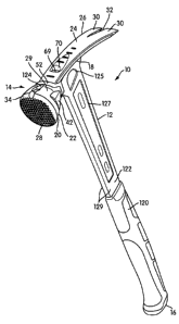
includes a handle and a head. The handle has a bottom end and an upper end.
The head
is disposed on the upper end of the handle and the head has a bell portion and
a claw
portion. The hammer having an overall length dimension and an overall mass
measurement. A ratio of the overall length dimension of the hammer measured in
inches
to the overall mass measurement of the hammer measured in ounces is less than
2.10.
[0006] Yet another aspect of the present invention provides a hammer that
includes a handle and a head. The handle has a bottom end and an upper end.
The head
is disposed on the upper end of the handle and the head has a bell portion and
a claw
portion. The hammer having an overall length dimension and the head of the
hammer
having a weight measurement. A ratio of the weight measurement of the head of
the
hammer measured in ounces to the overall length dimension of the hammer
measured in
inches is less than 1.10.
[0007] Yet another aspect of the present invention provides a hammer that
includes a handle and a head. The handle has a bottom end and an upper end.
The head
is disposed on the upper end of the handle and the head has a bell portion and
a claw
portion. The hammer having an overall weight measurement and the head of the
hammer having a weight measurement. A ratio of the overall weight measurement
of the
hammer measured in ounces to the weight measurement of the head of the hammer
measured in ounces is at least 1.98.
[0008] Yet another aspect of the present invention provides a hammer that
includes a handle and a head. The handle has a bottom end and an upper end.
The head
is disposed on the upper end of the handle and the head has a bell portion and
a claw
portion. The hammer having an overall weight measurement and the head of the
CA 02762018 2011-12-15
-3 -
hammer having a weight measurement. A ratio of the overall weight measurement
of the
hammer measured in ounces to the weight measurement of the handle of the
hammer
measured in ounces is less than 2.02.
[0009] These and other aspects of the present invention, as well as the
methods
of operation and functions of the related elements of structure and the
combination of
parts and economies of manufacture, will become more apparent upon
consideration of
the following description and the appended claims with reference to the
accompanying
drawings, all of which form a part of this specification, wherein like
reference numerals
designate corresponding parts in the various figures. In one embodiment of the
invention,
the structural components illustrated herein are drawn to scale. It is to be
expressly
understood, however, that the drawings are for the purpose of illustration and
description
only and are not intended as a definition of the limits of the invention. It
shall also be
appreciated that the features of one embodiment disclosed herein can be used
in other
embodiments disclosed herein. As used in the specification and in the claims,
the
singular form of "a", "an", and "the" include plural referents unless the
context clearly
dictates otherwise.
BRIEF DESCRIPTION OF THE DRAWINGS
[0010] FIG. 1 is a perspective view of a hammer in accordance with an
embodiment of the present invention;
[0011] FIG. 2 is a front view of the hammer in accordance with an
embodiment of the present invention;
[0012] FIG. 3 is a rear view of the hammer in accordance with an embodiment
of the present invention;
[0013] FIG. 4 is a left hand side elevational view of the hammer in accordance
with an embodiment of the present invention;
[0014] FIG. 5 is a right hand side elevational view of the hammer in
accordance with an embodiment of the present invention;
CA 02762018 2011-12-15
-4-
[0015] FIG. 6 is a top view of the hammer in accordance with an embodiment
of the present invention;
[0016] FIG. 7 is a bottom view of the hammer in accordance with an
embodiment of the present invention;
[0017] FIG. 8 is an exploded view of the hammer, with grip portions of the
handle removed for sake of clarity, in accordance with an embodiment of the
present
invention;
[0018] FIG. 9 is another exploded view of the hammer, with grip portions of
the handle removed for sake of clarity, in accordance with an embodiment of
the present
invention;
[0019] FIG. 10 is a side perspective view of a bell portion of the hammer in
accordance with an embodiment of the present invention;
[0020] FIG. 11 is another side perspective view of a bell portion of the
hammer
in accordance with an embodiment of the present invention;
[0021] FIG. 12 is a left hand side elevational of the bell portion in
accordance
with an embodiment of the present invention;
[0022] FIG. 13 is a top view of the bell portion in accordance with an
embodiment of the present invention;
[0023] FIG. 14 is a sectional view thereof along the line 14--14 of FIG. 12 in
accordance with an embodiment of the present invention;
[0024] FIG. 15 is a right hand side elevational view of the bell portion in
accordance with an embodiment of the present invention;
[0025] FIG. 16 is a side perspective view of a claw portion of the hammer in
accordance with an embodiment of the present invention;
[0026] FIG. 17 is another perspective view of a claw portion of the hammer in
accordance with an embodiment of the present invention;
CA 02762018 2011-12-15
- 5 -
[0027] FIG. 18 is a top view of the claw portion in accordance with an
embodiment of the present invention;
[0028] FIG. 19 is a bottom view of the claw portion in accordance with an
embodiment of the present invention;
[0029] FIG. 20 is a sectional view thereof along the line 20-20 of FIG. 18 in
accordance with an embodiment of the present invention;
[0030] FIG. 21 is a right hand side elevational view of the claw portion in
accordance with an embodiment of the present invention;
[0031] FIG. 22 is a side perspective view of the handle in accordance with an
embodiment of the present invention;
[0032] FIG. 23 is a front view of the handle in accordance with an embodiment
of the present invention;
[0033] FIG. 24 is a side elevational view of the handle in accordance with an
embodiment of the present invention;
[0034] FIG. 25 is detailed view of a projection disposed on the handle in
accordance with an embodiment of the present invention;
[0035] FIG. 26 is a sectional view thereof along the line 26--26 of FIG. 24 in
accordance with an embodiment of the present invention;
[0036] FIG. 27 is a sectional view thereof along the line 27--27 of FIG. 24 in
accordance with an embodiment of the present invention;
[0037] FIG. 28 is an assembled view of the hammer in accordance with an
embodiment of the present invention;
[0038] FIG. 29 is a side perspective view of the handle in accordance with
another embodiment of the present invention;
[0039] FIG. 30 is a front view of the handle in accordance with another
embodiment of the present invention;
CA 02762018 2011-12-15
-6 -
[0040] FIG. 31 is a side elevational view of the handle in accordance with
another embodiment of the present invention;
[0041] FIG. 32 is detailed view of a projection disposed on the handle in
accordance with another embodiment of the present invention;
[0042] FIG. 33 is a sectional view thereof along the line 33--33 of FIG. 30 in
accordance with another embodiment of the present invention;
[0043] FIG. 34 is a sectional view thereof along the line 34--34 of FIG. 30 in
accordance with another embodiment of the present invention;
[0044] FIG. 35 is an assembled view of the hammer in accordance with
another embodiment of the present invention;
[0045] FIG. 36A is a partial front view of the hammer in accordance with an
embodiment of the present invention;
[0046] FIG. 36B is a partial left hand side elevational view of the hammer
illustrating a central axis of a strike surface of the bell portion in
accordance with an
embodiment of the present invention;
[0047] FIG. 37 is a sectional view thereof along the line A--A of FIG. 36B in
accordance with an embodiment of the present invention;
[0048] FIG. 38 is a sectional view thereof along the line B--B of FIG. 36B in
accordance with an embodiment of the present invention;
[0049] FIG. 39 is a sectional view thereof along the line C--C of FIG. 36B in
accordance with an embodiment of the present invention;
[0050] FIG. 40 is a sectional view thereof along the line D--D of FIG. 36B in
accordance with an embodiment of the present invention;
[0051] FIG. 41 is a sectional view thereof along the line E--E of FIG. 36B in
accordance with an embodiment of the present invention;
CA 02762018 2011-12-15
- 7 -
[0052] FIG. 42 is a sectional view thereof along the line F--F of FIG. 36B in
accordance with an embodiment of the present invention;
[0053] FIG. 43 is a perspective view of a hammer, with grip portions of the
handle removed for sake of clarity, in accordance with another embodiment of
the
present invention;
[0054] FIG. 44 is an exploded view of the hammer, with grip portions of the
handle removed for sake of clarity, in accordance with another embodiment of
the
present invention;
[0055] FIG. 45 is another perspective view of the hammer, with grip portions
of the handle removed for sake of clarity, in accordance with another
embodiment of the
present invention;
[0056] FIG. 46 shows TABLES 1-3, TABLE 1 provides measurement data
(e.g., width measurement of the head and thickness measurement of the handle)
measured at sections that are positioned at portions of the hammer where the
claw
portion adjoins the handle in accordance with the present invention, while
TABLES 2
and 3 provide the same measurement data for various hammers across a sampling
of
multiple brands and/or models;
[0057] FIG. 47 shows TABLES 4-7, TABLE 4 provides measurement data
(e.g., width measurement and thickness measurement of the handle) measured at
a
predetermined measurement sections of the hammer in accordance with the
present
invention, while TABLES 5-7 provide the same measurement data for various
hammers
across a sampling of multiple brands and/or models;
[0058] FIG. 48 shows an exemplary hammer being sectioned as shown in order
to obtain weight of the head and weight of the handle; and
[0059] FIG. 49 shows a TABLE 8 providing a comparison and overview of
embodiments of the hammers in accordance with the present invention in
comparison
with various hammers across a sampling of multiple brands and/or models;
CA 02762018 2011-12-15
-8-
DETAILED DESCRIPTION OF THE INVENTION
[0060] FIGS. 1-7 show a hammer 10 in accordance with an embodiment of the
present invention. The hammer 10 includes a handle 12 and a head 14. The
handle 12
includes a bottom end 16 and an upper end 18. The head 14 is disposed on the
upper end
18 of the handle 12. The head 14 and the handle 12 are separately formed
structures. A
weld connection 56 (as shown in FIGS. 2 and 45) connects the head 14 with the
handle
12.
[0061] In one embodiment, the handle 12 is formed from sheet metal having a
thickness of less than 8 mm. In another embodiment, the handle 12 is formed
from sheet
metal having a thickness between 4 and 6 mm. In yet another embodiment, the
handle
12 is formed from sheet metal having a thickness between 4.5 and 5.5 mm.
[0062] FIGS. 1-7 show views of the illustrative hammer 10 in its assembled
condition. In one embodiment, the head 14 includes a bell portion 20 at one
end 22 and
a claw portion 24 at the other end 26 thereof.
[0063] As shown in FIG. 2, the hammer 10 includes an overall length
dimension OAL. In one embodiment, as shown in FIG. 2, the overall length
dimension
OAL of the hammer 10 is measured along (or relative to) the central
longitudinal axis L-
L of the hammer 10. The overall length dimension OAL is measured from the
bottom-
most end surface 16 of the handle 12 to a top most end 54 of the head 14,
taken along
axis L-L as shown. In the illustrated embodiment, the top-most axial point of
the head 14
is disposed at a top surface of the bell portion 20.
[0064] In one embodiment, as shown in FIGS. 1-7, the handle 12, the bell
portion 20 and the claw portion 24 are separately formed structures. A weld
connection
52 connects the bell portion 20 with the claw portion 24, a weld connection 53
connects
the bell portion 20 with the handle 12, and a weld connection 55 connects the
claw
portion 24 with the handle 12. The method of securing these separately formed
structures to each other is described in detail below.
[0065] In another embodiment, as shown and explained with respect to FIGS.
43-45, the bell portion 20 and the claw portion 24 are one-piece integral
structures. In
CA 02762018 2011-12-15
-9 -
such an embodiment, the integrally formed bell portion 20 and claw portion 24
are joined
with the separately formed handle 12. For example, the weld connection 56 (as
shown in
FIG. 45) connects the integrally formed bell portion 20 with claw portion 24
and the
handle 12.
[0066] In one embodiment, the handle 12 is formed chromium molybdenum
(chromoly) steel. For example, the handle 12 may be formed 4130 chromoly steel
or
4135 chromoly steel. In one embodiment, the handle 12 is made from chromium-
molybdenum steel of a different grade than that that of the bell portion 20 or
of the claw
portion 24.
[0067] In one embodiment, the handle or shaft 12 is made from steel having a
lower carbon content than that used for the claw portion 24 or the bell
portion 20. When
the hammer 10 undergoes a heat treatment process, the low carbon steel
material
provides the handle 12 with a lower hardness, which in turn provides a
vibration
dampening for the hammer 10.
[0068] In one embodiment, the handle 12 is made of a composite material. In
another embodiment, the handle 12 of the hammer 10 is made from stamped sheet
metal.
In other embodiments, the handle 12 is formed from a carbon steel material.
For
example, the handle 12 may be formed AISI 1060 steel. In one embodiment, the
handle
12 is made from aluminum material.
[0069] In one embodiment, the handle 12 is formed by stamping. In another
embodiment, the handle 12 is formed by laser cutting or water jet cutting. In
other
embodiments, the handle 12 is formed by fine blanking, plasma cutting,
electrochemical
machining, electrical discharge machining, cold forging, hot forging, milling,
die cutting,
computer numeric controlled machining operation, or any other suitable
machining or
manufacturing process. In yet other embodiments, the handle 12 may be rolled
or
extruded.
[0070] As shown in FIGS. 1-5, the hammer 10 includes a manually engageable
grip portion 120. In one embodiment, the manually engageable grip portion 120
of the
hammer 10 is molded onto an inner or core portion 122 of the handle 12. In one
embodiment, the grip portion 120 of the handle 12 is made of an elastomeric
material, a
CA 02762018 2011-12-15
-10-
rubber based material, a plastic based material or other suitable material.
Optionally, the
grip portion 120 can be ergonomically shaped. In another embodiment, the grip
portion
120 is simply the outer surface of the handle material (e.g., metal).
[0071] In one embodiment, a surface texture or pattern (e.g., ribbed) may be
provided on the grip portion 120. The surface texture or pattern is
constructed and
arranged to improve the grip of the user. The surface texture or pattern may
be provided
by knurling, sand blasting, rubber coating, or any other surface texturing
methods known
in the art. In one embodiment, the grip portion 120 may include a slip-
resistant surface
that is constructed and arranged to be used in all weather conditions. In one
embodiment, the grip portion 120 may include a cushioned grip.
[0072] In one embodiment, the manually engageable grip portion 120 (e.g.,
made from a plastic based material) may be partially or entirely over-molded
onto the
inner or core portion 122 of the handle 12 to mimic the appearance of the two-
piece
hammer, for example. The over-molded plastic portion may serve as a protective
covering for environments where metal to metal contact may damage portion of
the
hammer that is being struck. For example, the hammer with the over-molded
plastic
portion may provide different functions, such as spark resistance, overstrike
protection,
or simply provide an aesthetic appearance. In one embodiment, a surface 155
(near the
lower end 16 of the hammer) of the manually engageable grip portion 120 may
have
indicia (not shown) such as instructions for using the hammer 10.
[0073] In one embodiment, the manually engageable grip portion 120 is
formed from one or two layers of resilient material that may be configured to
reduce
vibration and provide torsion control.
[0074] In one embodiment, the hammer 10 may optionally include an over-
strike protector structure constructed and arranged to surround a portion of
the handle 12
adjacent to (beneath) the upper end 18 of the handle 12. The over-strike
protector
structure is constructed and arranged to protect the handle 12 and/or reduce
vibration
imparted to the user's hand during an overstrike (i.e., when a strike surface
28 of the
hammer 10 misses an intended object, such as nail or a chisel, and the handle
12 strikes
the wood or other surface). In one embodiment, the over-strike protector
structure
CA 02762018 2011-12-15
- 11 -
includes an additional or extra layer or mass of resilient material (such as
an elastomer or
rubber based material) molded on the portion of the handle 12 to dissipate
impact energy
and stress due to an overstrike. In one embodiment, the over-strike protector
structure is
constructed and arranged to provide a high degree of cushioning to protect the
user's
hand from the kinetic energy transferred thereto during impact of the striking
surface
against the object, such as a nail or a chisel.
[0075] FIGS. 8 and 9 show exploded views of the hammer 10, with the grip
portion 120 removed for sake of clarity, in accordance with an embodiment of
the
present invention. FIGS. 8 and 9 show the hammer 10 in which the handle 12,
the bell
portion 20 and the claw portion 24 are separately formed structures. These
separately
formed structures are secured to each other, for example, using weld
connections. The
handle core portions 122 of the hammers shown in FIGS. 8 and 9 are different
from each
other. These handle core portions 122 of the hammers shown in FIGS. 8 and 9
are
explained in further detail with respect FIGS. 22-34.
[0076] Detail views of the bell portion 20 are shown in FIGS. 10-15. FIGS. 12-
15 show portions and dimensions of various parts of the bell portion in
accordance with
an embodiment of the present invention. The portions and dimensions of various
parts of
the bell portion shown in FIGS. 12-15 are intended to be merely exemplary and
not
limiting in any way. The various parts of the bell portion shown in FIGS. 12-
15 are
drawn to scale in accordance with one embodiment, although other scales and
shapes
may be used in other embodiments. The dimensions of various parts of the bell
portion
as shown in FIGS. 12-15 are measured in millimeters unless indicated
otherwise. In one
embodiment, the dimensions of various parts of the bell portion, as shown in
FIGS. 12-
15, are up to 10 percent greater than or up to 10 percent less than those
illustrated. In
another embodiment, the dimensions of various parts of the bell portion, as
shown in
FIGS. 12-15, are up to 5 percent greater than or up to 5 percent less than
those
illustrated.
[0077] In one embodiment, the weight of the bell portion 20 is within the
range
of from approximately 0.178 kilograms to 0.196 kilograms. In one embodiment,
the
weight of the bell portion 20 is 0.187 kilograms.
CA 02762018 2011-12-15
-12-
[0078] In one embodiment, the bell portion 20 is formed chromium
molybdenum (chromoly) steel. For example, the bell portion 20 may be formed
4140
chromoly steel. In one embodiment, the bell portion 20 is made from chromoly
steel of a
different grade than that of the handle 12. In one embodiment, the bell
portion 20 is
made from substantially same grade of chromoly steel as the claw portion 24.
Chromoly
steel is used to provide structural strength and toughness to the bell portion
20.
[0079] In another embodiment, the bell portion 20 is made from a shock
resistant tool steel to withstand impact. In another embodiment, the bell
portion 20 is
formed from cold formed metal. In other embodiments, the bell portion 20 is
formed
from a carbon steel material. For example, the bell portion 20 may be formed
AISI 1060
steel or AISI 1055 steel.
[0080] In one embodiment, the bell portion is formed from cold forging. In
other embodiments, the bell portion 20 may be formed by hot forging, cold
forming, cold
heading, casting, rolling, extrusion, metal injection molding (MIM), or formed
from
stamped sheet metal.
[0081] When the bell portion 20 is made from the metal injection molding
(MIM) operation, the bell portion 20 may be made using a powered metal
material. The
metal injection molding is configured to eliminate the need for secondary
forming
operations on the bell portion 20. For example, the "waffle" pattern that is
generally
machined onto a strike surface 28 of the head 14 may be made during the same
operation
that makes the bell portion 20.
[0082] The bell portion 20 located at the forward portion of the head 14 of
the
hammer 10 includes the strike surface 28. A chamfer or bevel 34 is located
circumferentially along the edges of the strike surface 28 of the hammer 10.
When the
hammer 10 is swung in a swing plane of the hammer, the strike surface 28
strikes an
object, such as a nail or a chisel.
[0083] In one embodiment, the strike surface 28 of the hammer 10 is slightly
convex in order to facilitate square contact during driving of nails. In one
embodiment,
as can be clearly seen in FIGS. 13 and 14, the strike surface 28 is convex in
both
horizontal and vertical directions.
CA 02762018 2011-12-15
- 13 -
[0084] In one embodiment, the strike surface 28 may be made larger while
keeping the overall weight of the hammer 10 lower (i.e., when compared to
traditional
hammers made from steel). In one embodiment, a ratio of head weight of the
hammer,
measured in ounces at 3.0 inches from top of the head, to surface area of the
striking
surface of the head measured in square inches, is less than 16.25. In another
embodiment, a ratio of the head weight of the hammer measured in ounces to the
surface
area of the striking surface of the head measured in square inches is less
than 14Ø A
hammer having such a large strike surface configuration is described in detail
in a U.S.
Patent No. 8,047,099, filed on May 18, 2009 and issued on November 1, 2011,
the
entirety of which is hereby incorporated into the present application by
reference.
[0085] In one embodiment, an additional or extra portion of the hammer's
mass may be concentrated in the bell portion 20 or behind the strike surface
28. During
use the hammer generally rotates along the handle axis due to the mass of the
claw
portion, which continues forward after the blow has been delivered. This
rotation may
cause fatigue to the user since the user must continuously try to counter the
rotation of
the hammer during the striking by the squeezing the grip harder. The hammer 10
of the
present invention is constructed and arranged to counter the rotation of the
hammer
during the striking of the object by concentrating more of the hammer's mass
in the bell
portion 20 or behind the strike surface 28.
[0086] In one embodiment, the bell portion 20 tapers so as to be reducing in
diameter as it extends away from the chamfer 34. In one embodiment, the bell
portion
20 is devoid of a cylindrically shaped structure, and wherein the tapered
portion 29 of the
bell portion 20 adjoins the chamfer 34.
[0087] In one embodiment, a plurality of circumferentially spaced recesses 42
are located adjacent to but spaced from the strike surface 28 of the head 14.
A relatively
large strike surface 28 is provided without substantially increasing the
overall weight of
the overall hammer 10 or of the head 14 by providing these recesses 42. The
material in
these plurality of circumferentially spaced recesses 42 is removed in
comparison with
prior art configurations; the term "removed" as used herein does not require
that the
material first be provided in such regions and then taken away. Rather the
recesses can
be formed during the initial machining or manufacturing process of the bell
portion, or
CA 02762018 2011-12-15
- 14 -
can be formed after the initial machining or manufacturing process of the bell
portion to
provide a large strike surface 28 and maintain the overall weight of the
hammer 10.
[0088] In one embodiment, the bell portion 20 may include claw portion
receiving portion 58 (as shown in FIGS. 11 and 15) that is constructed and
arranged to
receive a portion 60 (as shown in FIGS. 16-20) of the claw portion 24, when
securing the
bell portion 20 to the claw portion 24, for example, using a welding
operation. In
another embodiment, as noted above, the bell portion 20 and the claw portion
24 may be
integrally formed as one-piece structures. In such an embodiment, the bell
portion 20
may not include the claw portion receiving portion 58.
[0089] In one embodiment, the bell portion 20 may include handle receiving
portion 59 (as shown in FIGS. 11 and 15) that is constructed and arranged to
receive a
portion 61 (as shown in FIGS. 22, 23, 29 and 30) of the handle 12, when
securing the
bell portion 20 to the handle 12, for example, using a welding operation.
[0090] In one embodiment, a groove 124 may be located along a top surface of
the bell portion 20. The groove 124, if provided, is constructed and arranged
to receive
and retain a portion of a nail 71 (shown in dashed lines in FIG. 2) therein,
when the nail
71 is placed in an initial nail driving position to facilitate the start of a
nail driving
operation.
[0091] In one embodiment, as shown in FIGS. 11, 13, and 14, an opening 66
located on the top surface of the bell portion 20 that is configured to
receive a magnet 67.
The magnet 67 is constructed and arranged to help retain the nail 71 in the
initial nail
driving position in the groove 124 to facilitate the start of the nail driving
operation.
[0092] Referring to FIGS. 1 and 2, a notch 70 is disposed on the top surface
head 14. As shown in FIG. 2, a surface 69 of the hammer 10 is constructed and
arranged
to support a head of the nail 71 (shown in dashed lines in FIG. 2). In one
embodiment,
the notch 70 and the surface 69 are formed on the top surface of the claw
portion 24.
Thus, the groove 124, the magnet 67, and the surface 69 act together to
position and to
initially drive the nail 71 in a first blow into a work piece. The nail
starter arrangement
that includes the groove 124, magnet 67, and the surface 69 is optional.
CA 02762018 2011-12-15
-15-
[0093] Detail views of the claw portion 24 are shown in FIGS. 16-21. FIGS.
18-21 show portions and dimensions of various parts of the claw portion in
accordance
with an embodiment of the present invention. The portions and dimensions of
various
parts of the claw portion shown in FIGS. 18-21 are intended to be merely
exemplary and
not limiting in any way. The various parts of the claw portion shown in FIGS.
18-21 are
drawn to scale in accordance with one embodiment, although other scales and
shapes
may be used in other embodiments. The dimensions of various parts of the claw
portion
as shown in FIGS. 18-21 are measured in millimeters unless indicated
otherwise. In one
embodiment, the dimensions of various parts of the claw portion, as shown in
FIGS. 18-
21, are up to 10 percent greater than or up to 10 percent less than those
illustrated. In
another embodiment, the dimensions of various parts of the claw portion, as
shown in
FIGS. 18-21, are up to 5 percent greater than or up to 5 percent less than
those
illustrated.
[0094] In one embodiment, the weight of the claw portion 24 is within the
range of from approximately 0.134 kilograms to 0.148 kilograms. In one
embodiment,
the weight of the claw portion 24 is 0.141 kilograms.
[0095] In one embodiment, the claw portion 24 is formed chromium
molybdenum (chromoly) steel. For example, the claw portion 24 may be formed
4140
chromoly steel. In one embodiment, the claw portion 24 is made from chromoly
steel
material of a different grade than that of the handle 12. In one embodiment,
the claw
portion 24 is made from substantially same grade of chromoly steel as the bell
portion
20. Chromoly steel is used to provide structural strength and toughness to the
claw
portion 24.
[0096] In another embodiment, the claw portion 24 is made from high carbon
spring steel material. The high carbon steel material provides not only high
hardness but
also high yield strength to the claw portion 24. In one embodiment, the claw
portion 24
is formed from stamped sheet metal. In other embodiments, the claw portion 24
is
formed from a carbon steel material. For example, the claw portion 24 may be
formed
AISI 1060 steel or AISI 1055 steel.
CA 02762018 2011-12-15
- 16 -
[0097] In one embodiment, the claw portion 24 is formed from hot forging. In
another embodiment, the claw portion 24 is formed from stamping sheet metal or
cold
forging. In other embodiments, the claw portion 24 may be cold forming,
forging,
casting, rolling, extrusion, or metal injection molding.
[0098] In the illustrated embodiment, as shown in FIGS. 16-19, the claw
portion 24 of the head 14 includes a pair of tapered, spaced-apart (forked)
nail removing
members 30. The nail removing members 30 provide a V-shaped or triangular
space 32
therebetween. The shank of a nail can be received in the V-shaped space 32
with the top
of the hammer 10 facing the work piece and the nail is removed by engaging the
spaced
apart claw members 30 with the head of the nail and withdrawing the nail from
a work
piece.
[0099] In some embodiments, a forked claw portion is not provided, but rather
a single rearwardly extending portion is provided, as is known in masonry
applications.
Such single rear portion is not typically considered to be a "claw" in the
art, as a single
rear portion has a different function and purpose than a nail pulling claw.
For
convenience and for the purposes of the claims contained in this application,
however,
the term "claw portion" as used herein should be construed broadly to cover a
single rear
extension as well as the forked arrangement.
[00100] In one embodiment, the claw portion 24 is generally straight to
provide
a rip or straight claw hammer that is constructed and arranged for use in
framing and
ripping. In another embodiment, the claw portion 24 is generally curved to
provide a
curved claw hammer that is constructed and arranged to remove nails.
[00101] In one embodiment, the claw portion 24 of the head 14 may include
handle receiving opening(s) on a bottom surface 27 thereof that are
constructed and
arranged to receive a portion of the handle 12, when securing the claw portion
24 to the
handle 12, for example, using a welding operation. In another embodiment, the
claw
portion 24 may not have any such opening(s) on the bottom surface 27. In such
an
embodiment, the handle 12 is held in place against the bottom surface while it
is being
welded or secured to the claw portion 24.
CA 02762018 2011-12-15
-17-
[00102] In one embodiment, the claw portion 24 may include the portion 60 (as
shown in FIGS. 16-20) that is constructed and arranged to be received in the
claw
portion receiving portion 58 (as shown in FIGS. 11 and 15) of the bell portion
20, when
securing the bell portion 20 to the claw portion 24, for example, using a
welding
operation.
[00103] Detail views of the handle, without the grip portion, are shown in
FIGS.
22-27 and 29-34. FIGS. 23-27 show portions and dimensions of various parts of
handle
core portion 122 in accordance with an embodiment of the present invention,
while
FIGS. 30-34 show portions and dimensions of various parts of the handle core
portion
122 in accordance with another embodiment of the present invention.
[00104] The portions and dimensions of various parts of the handle core
portion
122 shown in FIGS. 22-27 and 29-34 are intended to be merely exemplary and not
limiting in any way. The various parts of the handle core portion 122 shown in
FIGS.
22-27 and 29-34 are drawn to scale in accordance with one embodiment, although
other
scales and shapes may be used in other embodiments. The dimensions of various
parts
of the handle core portion 122 as shown in FIGS. 22-27 and 29-34 are measured
in
millimeters unless indicated otherwise. In one embodiment, the dimensions of
various
parts of the handle core portion 122, as shown in FIGS. 22-27 and 29-34, are
up to 10
percent greater than or up to 10 percent less than those illustrated. In
another
embodiment, the dimensions of various parts of the handle core portion 122, as
shown in
FIGS. 22-27 and 29-34, are up to 5 percent greater than or up to 5 percent
less than those
illustrated.
[00105] In one embodiment, the weight of the handle 12 (without the grip
portion 120) or handle core portion 122 is within the range of from
approximately 0.32
kilograms to 0.362 kilograms. In one embodiment, the weight of the handle core
portion
122 (as shown in FIGS. 22-27) is within the range of from approximately 0.328
kilograms to 0.362 kilograms. In one embodiment, the weight of the handle core
portion
122 is 0.345 kilograms. In another embodiment, the weight of the handle core
portion
122 (as shown in FIGS. 29-34) is within the range of from approximately 0.32
kilograms
to 0.354 kilograms. In one embodiment, the weight of the handle core portion
122 is
0.337 kilograms.
CA 02762018 2011-12-15
-18-
[00106] As shown in FIGS. 1-3 and 22-23, in one embodiment, the handle core
portion 122 may include recess portions 125 or 127 on at least one side
surface 129
thereof so as to reduce the overall weight of the hammer 10. In one
embodiment, the
handle 12 may include recess portion 125 and elongated recess portion 127. In
another
embodiment, as shown in FIGS. 29 and 30, the handle core portion 122 may
include an
elongated recess portion 131 on at least one side surface 129 thereof.
[00107] In one embodiment, the recess portions 125, 127 or 131 may have
advertising or promotional information such as indicia (not shown) for
identifying the
product and/or manufacturer to the customers. These recess portions 125, 127
or 131
can be formed during the initial machining or manufacturing process of the
handle core
portion 122, or can be formed after the initial machining or manufacturing
process of the
handle core portion 122.
[00108] The elongated recess portions 127 and 131 are configured to extend for
at least a certain length of the handle core portion 122. The handle core
portion 122 has
a substantially uniform thickness except for the portions where the recess
portions 125,
127 or 131 are disposed. That is, the portions of the handle core portion 122
where
recess portions are disposed have reduced or decreased thickness than the rest
of the
handle core portion 122.
[00109] Peripheral edge surfaces 133 of the recess portions 125, 127 or 131
facilitate gradually blending or transition of the recess portions 125, 127 or
131 to the
surrounding handle portions.
[00110] In one embodiment, the handle core portion 122 may include the
portion 61 (as shown in FIGS. 22, 23, 29 and 30) that is constructed and
arranged to be
received in the handle receiving portion 59 (as shown in FIGS. 11 and 15) of
the bell
portion 20, when securing the bell portion 20 to the handle core portion 122,
for
example, using a welding operation.
[00111] In one embodiment, as shown in FIGS. 22, 23, 29 and 30, the handle
core portion 122 may include a plurality of projections 135 and an opening 137
positioned on a lower half section 139 of the handle core portion 122. In one
embodiment, the handle core portion 122 and the grip portion 120 (as shown in
FIGS. 1-
CA 02762018 2011-12-15
-19-
5) are secured together and are interlocked by the projections 18 extending
into the grip
portion 120. In one embodiment, the grip portion 120 has a portion disposed in
the
opening 137 to interlock the grip portion 120 and the handle core portion 122,
when the
grip portion 120 is being secured to the handle core portion 122. Detailed
views of the
projections are shown in FIGS. 25 and 32.
[00112] In one embodiment, the handle core portion 122 includes a surface 141
that is constructed and arranged to engage with or rest against the surface 27
of the claw
portion 24, when securing the claw portion 24 to the handle 12, for example,
using a
welding operation.
[00113] FIGS. 26 and 27 show sectional views of the handle core portion 122
(as shown in FIGS. 22-24) along the lines 26--26 and 27--27 of FIG. 24 in
accordance
with an embodiment of the present invention. FIGS. 33 and 34 show sectional
views of
the handle core portion 122 (as shown in FIGS. 29-31) along the lines 33--33
and 34--34
of FIG. 30 in accordance with an embodiment of the present invention.
[00114] FIG. 26 shows a section view of the handle core portion 122 in a
portion in which the recess portion 127 is disposed, while FIG. 33 shows a
section view
of the handle core portion 122 in a portion in which the recess portion 131 is
disposed.
As shown in the illustrative embodiments of FIGS. 26 and 33, the handle core
portion
122 has an I-shaped cross-sectional configuration in portions where the recess
portion
127 or 131 is disposed. Such I-shaped cross-section configuration has a
central web
portion 145 having a reduced or decreased thickness than the surrounding
flange portions
147. Such I-shaped cross-section configuration is configured to increase the
strength of
the handle core portion while reducing the material usage. Other cross-
sectional shapes
are also contemplated as within the scope of this invention.
[00115] In the illustrative embodiment of FIG. 33, the central web portion 145
has a substantially uniform thickness and the surrounding flange portions 147
have a
substantially uniform thickness that is different from the thickness of the
central web
portion 145.
[00116] In another embodiment, as shown in FIG. 26, the central web portion
145 may have varying thickness along the central web portion 145. In one
embodiment,
CA 02762018 2011-12-15
- 20 -
the central web portion 145 may have a stepped cross-sectional configuration.
In one
embodiment, thickness of a central portion 151 of the web portion 145 is lower
than the
thickness of the surrounding portions 153 of the web portion 145.
[00117] FIGS. 27 and 34 show section views of the handle core portions 122 in
portions having no recess portions. As shown in the illustrative embodiment of
FIGS. 27
and 34, the thickness of the handle core portion is substantially uniform in
the portions
with no recess portions.
[00118] As shown in the cross-sectional views of FIGS. 26 and 27, in one
embodiment, the handle core portion 122 has substantially rounded corner
portions 143.
[00119] FIGS. 28 and 34 show hammers in their assembled view. The hammers
in FIGS. 28 and 34 are similar to each other, except for the differences as
will noted
below.
[00120] The hammer shown in FIG. 28 has the handle core portion 122 as
shown in FIGS. 22-27, while hammer shown in FIG. 34 has the handle core
portion 122
as shown in FIGS. 29-34. In illustrated embodiment, as shown in FIGS. 28 and
34, the
grip portions of the hammers are different from each other. In another
embodiment, the
grip portions of the hammers may be same.
[00121] In one embodiment, the components of the hammer, such as the handle
12, the claw portion 24 and the bell portion 20, may be made from any suitable
metallic
materials that are selected for their intended use and cost. For example, a
steel hammer
having a weight similar to that of a titanium hammer may be economically
produced.
[00122] In one embodiment, the handle 12, the claw portion 24, and the bell
portion 20 are formed from dissimilar materials. In another embodiment, the
claw
portion 24 and the bell portion 20 are formed from same material and are
connected to
the handle 12 formed from a different material. In yet another embodiment, the
claw
portion 24 and the bell portion 20 are integrally formed from same material
and are
connected to the handle 12 formed from a different material.
[00123] In non-limiting examples, the weight of the hammer 10 having
separately formed bell portion, claw portion and handle is nominally between
26.5 and
CA 02762018 2011-12-15
-21 -
31.0 ounces; and the overall length dimension of such hammer is between 13.5
and 16.5
inches.
[00124] In non-limiting examples, the weight of the hammer 10 having handle
and integrally formed bell portion and the claw portion is nominally between
26.5 and
31.0 ounces; and the overall length dimension of such hammer is between 13.5
and 16.5
inches.
[00125] The amount of energy a hammer can deliver, called kinetic energy
(KE), is a function of the weight of the hammer and the speed at which it
travels. The
equation 1 provides the formula for Kinetic Energy.
Kinetic Energy (KE) = (1/2) x m x v2 Equation (1)
where m = mass (weight of the hammer)
v = velocity (speed at which the hammer is traveling)
[00126] As can be seen from the above Equation (1), velocity (v) has much
more influence than mass (m) on the amount of energy the hammer can deliver
because
the value of velocity is squared. A user typically swings a lighter hammer
faster.
[00127] For example, a 28oz (e.g., made by Estwing ) framing hammer, with a
total weight of 1.09 kilograms (Kg) may be swung at around 10 meters per
second (m/s)
of velocity to deliver approximately 55 joules of kinetic energy. In contrast,
the hammer
of the present application, with a total weight of approximately 0.8 Kilograms
(Kgs),
may be swung at around 12.2 meters per second (m/s) of velocity to deliver
approximately 60 joules of kinetic energy. In one embodiment, the hammer
described in
the present application weighs 35-40% less than a traditional 28oz framing
hammer.
[00128] FIG. 36A shows a partial front view of the hammer and FIG. 36B
shows a partial left hand side elevational view of the hammer 10 illustrating
different
cross-sections being therethrough in accordance with an embodiment of the
present
invention. FIGS. 37-42 show the progressive cross-sectional views of the
hammer 10
taken along various sections A-A through F-F of FIG. 36B. FIGS. 37-42 show
width
CA 02762018 2011-12-15
-22 -
measurement A of the head 14 and the maximum thickness measurement 13 of the
handle
core portion 122 measured at section lines A-A through F-F, respectively.
[00129] TABLES 1-3 in FIG. 46 provide a comparison and overview of
particular embodiments of the hammer in accordance with the invention
disclosed herein
in comparison with various hammers across a sampling multiple brands and/or
models.
Among other things, these tables provide a comparative or a relative
measurement of the
ratio of width measurement of the head to maximum thickness measurement of the
handle for the various hammers.
[00130] The top row of each table has a model number of the hammer under
consideration. For example, TABLE 1 provides the measurement data for Stanley
FatMax Framing Rip Claw hammer described and shown with respect to FIGS. 29-35
of
the present application. TABLES 2 and 3 provide the measurement data for
Estwing
22ounces Straight Rip Claw Framing Hammer (model number: E322S) and Plumb
(Cooper hand tools) 28ounces Solid Steel Rip Hammer (model number: SS28RCF),
respectively.
[00131] The first column in TABLES 1-3 provides a section at which the width
measurement of the head and the thickness of the handle are taken. In one
embodiment,
as shown in FIG. 36B, the sections A-A through F-F are positioned at portions
of the
hammer 10 where the head 14 adjoins the handle 12. In one embodiment, the
sections
A-A through F-F are taken generally parallel to a longitudinal axis L--L of
the hammer
10, and generally perpendicular to a central axis X--X of the bell portion.
[00132] The second column in TABLES 1-3 provides a width measurement A
of the head measured at the section. In one embodiment, the width measurement
A of
the head is a width measurement A of the claw portion. In one embodiment, the
width
measurement A of the head is measured in millimeters.
[00133] The third column in TABLES 1-3 provides a thickness measurement B
of the handle measured at the section. In one embodiment, the thickness
measurement B
of the handle is a maximum thickness measurement B of the handle. As noted
above, the
handle may include cutouts, recesses portions or reduced thickness portions
125, 127 or
131 disposed thereon. In one embodiment, the maximum thickness measurement B
of
CA 02762018 2011-12-15
-23 -
the handle is a thickness measurement measured at the section at portions of
the handle
where the thickness of the handle is maximum (i.e., at portions of the handle
other than
where the cutouts or reduced thickness portions are disposed). In one
embodiment, the
thickness measurement B of the handle is measured in millimeters.
[00134] In the illustrated embodiment, the thickness measurement of the handle
is measured in a predefined area. In one embodiment, an upper boundary UB and
a
lower boundary LB of the predefined area may be parallel to the central axis X-
-X of the
bell portion. In one embodiment, the upper boundary UB of the predefined area
is a
parallel line that matches the upper contour of the head and is spaced 12
millimeters
away from the upper contour of the head. In one embodiment, the lower boundary
LB of
the predefined area may be parallel to the central axis X--X of the bell
portion and is
positioned at a longitudinal distance of 60 millimeters from the central axis
X--X of the
bell portion.
[00135] In one embodiment, a right side boundary RSB and a left side boundary
LSB of the predefined area may be parallel to the longitudinal axis L--L of
the hammer
10. In one embodiment, the right side boundary RSB and the left side boundary
LSB are
positioned at a distance of 25 millimeters from the longitudinal axis L--L of
the hammer
10 and on each side of the longitudinal axis L--L of the hammer 10.
[00136] The fourth column in TABLES 1-3 provides a ratio of the width
measurement A of the head 14 to the maximum thickness measurement B of the
handle
12. In one embodiment, a ratio of the width measurement A of the head 14 to
the
maximum thickness measurement B of the handle 12 is at least 2Ø
[00137] In one embodiment, the ratio of the width measurement A of the head
14 to the maximum thickness measurement B of the handle 12 is within the range
of
from approximately 4.0 to 5Ø
[00138] In one embodiment, the ratio of the width measurement A of the head
14 to the maximum thickness measurement B of the handle 12 is up to 40 percent
greater
than or up to 40 percent less than those noted in TABLE 1. In one embodiment,
the ratio
of the width measurement A of the head 14 to the maximum thickness measurement
B of
the handle 12 is up to 20 percent greater than or up to 20 percent less than
those noted in
CA 02762018 2011-12-15
-24 -
TABLE 1. In one embodiment, the ratio of the width measurement A of the head
14 to
the maximum thickness measurement B of the handle 12 is up to 10 percent
greater than
or up to 10 percent less than those noted in TABLE 1. In one embodiment, the
ratio of
the width measurement A of the head 14 to the maximum thickness measurement B
of
the handle 12 is up to 5 percent greater than or up to 5 percent less than
those noted in
TABLE 1.
[00139] In one embodiment, the ratio of the width measurement A of the head
14 to the maximum thickness measurement B of the handle 12 increases as the
section
lines move further away from the strike face 28.
[00140] TABLES 4-7 in FIG. 47 provide a comparison and overview of
particular embodiments of the hammer in accordance with the invention
disclosed herein
in comparison with various hammers across a sampling multiple brands and/or
models.
Among other things, these tables provide a comparative or a relative
measurement of the
ratio of maximum width measurement of the handle to maximum thickness
measurement
of the handle for the various hammers.
[00141] The top row of each table has a model number of the hammer under
consideration. For example, TABLE 4 provides the measurement data for Stanley
FatMax Framing Rip Claw hammer described and shown with respect to FIGS. 29-35
of
the present application. TABLES 5-7 provide the measurement data for EstWing
22ounces Straight Rip Claw Framing Hammer (model number: E322S), Plumb
(Cooper hand tools) 28ounces Solid Steel Rip Hammer (model number: SS28RCF)
and
Dead On (Dead On Tools(10) 22ounces 18-Inch Steel Milled Face Hammer (model
number: DOS22M), respectively.
[00142] The first column in TABLES 4-7 provides measurement sections. The
width measurement and thickness measurement of the handle are taken at one or
more
measurement sections. In one embodiment, the measurement sections taken along
a
measurement axis parallel to the central axis X--X of the bell portion 20,
between 20
millimeters and 40 millimeters below the central axis X--X of the bell portion
20.
[00143] In the illustrated embodiment, as shown in FIG. 36B, two measurement
sections MS1 and MS2 are shown. The first measurement section MS1 is taken
along a
CA 02762018 2011-12-15
-25 -
measurement axis 20--20 parallel to the central axis X--X of the bell portion
20 and is
positioned at 20 millimeters below the central axis X--X of the bell portion
20 and the
second measurement section MS2 is taken along a measurement axis 40--40
parallel to
the central axis X--X of the bell portion 20 and is positioned at 40
millimeters below the
central axis X--X of the bell portion 20. In one embodiment, width measurement
and
thickness measurement of the handle are taken at one or more measurement
sections that
are placed between the measurement sections MS1 and MS2.
[00144] The second column in TABLES 4-7 provides a width measurement of
the handle measured at the measurement section. In one embodiment, the width
measurement of the handle is a maximum width measurement of the handle. In one
embodiment, the width measurement of the handle is measured in millimeters.
[00145] The third column in TABLES 4-7 provides a thickness measurement of
the handle measured at the measurement section. In one embodiment, the
thickness
measurement of the handle is a maximum thickness measurement of the handle. In
one
embodiment, the thickness measurement of the handle is measured in
millimeters.
[00146] The fourth column in TABLES 4-7 provides a ratio of the maximum
width measurement to the maximum thickness measurement of the handle. In one
embodiment, a ratio of the maximum width measurement to the maximum thickness
measurement of the handle is at least 3.5.
[00147] In one embodiment, the ratio of the maximum width measurement to
the maximum thickness measurement of the handle is within the range of from
approximately 5.8 to 6.6.
[00148] In one embodiment, the ratio of the maximum width measurement to
the maximum thickness measurement of the handle is up to 40 percent greater
than or up
to 40 percent less than those noted in TABLE 4. In one embodiment, the ratio
of the
maximum width measurement to the maximum thickness measurement of the handle
is
up to 20 percent greater than or up to 20 percent less than those noted in
TABLE 4. In
one embodiment, the ratio of the maximum width measurement to the maximum
thickness measurement of the handle is up to 10 percent greater than or up to
10 percent
less than those noted in TABLE 4. In one embodiment, the ratio of the maximum
width
CA 02762018 2011-12-15
- 26 -
measurement to the maximum thickness measurement of the handle is up to 5
percent
greater than or up to 5 percent less than those noted in TABLE 4.
[00149] As can be appreciated from TABLES 4-7 and 8, in one aspect of the
hammer of the present invention, the weight of the present hammer is
distributed such
that it is less top heavy than prior art hammers. This weight distribution
allows the
hammer to be swung faster (with more velocity), imparting more kinetic energy
in
comparison with a hammer of equal weight, but in which there is more relative
weight in
the head.
[00150] In one embodiment, the ratio of the maximum width measurement to
the maximum thickness measurement of the handle 12 decreases as the
measurement
sections move further away from the central axis X--X of the bell portion 20.
[00151.] In one embodiment, a method of making a hammer includes forming
the handle core portion 122 from sheet metal; forming the claw portion 24;
forming the
bell portion 20; connecting or securing the sheet metal handle 122 to the bell
portion 20;
connecting or securing the claw portion 24 and the bell portion 20; and
pressing or over-
molding the manually gripping portion 120 onto the handle 12.
[00152] In one embodiment, a first piece of sheet metal is stamped to form the
handle 12, a second piece of metal is hot forged to form the claw portion 24
and a third
piece of metal is cold forged to form the bell portion 20.
[00153] In other embodiments, as noted above, the handle 12 may be formed
from laser cutting, water jet cutting, fine blanking, plasma cutting,
electrochemical
machining, electrical discharge machining, cold forging, hot forging, milling,
die
cutting, computer numeric controlled machining operation, or any other
suitable
machining process, the claw portion 24 may be formed from cold forming,
forging,
casting, rolling, extrusion, or metal injection molding, and the bell portion
20 may be
formed from hot forging, cold forming, cold heading, casting, rolling,
extrusion, metal
injection molding (MIM), or formed from stamped sheet metal.
[00154] In one embodiment, because a separately formed handle, made from
sheet metal, is connected to the head (e.g., by being welded), this permits
for the creation
CA 02762018 2011-12-15
-27 -
of unusual handle shapes (by stamping, laser cutting, etc.), particularly at
the transition
between the handle and head, and elsewhere in the handle. This enables the
hammer to
be provided with one or more of enhanced aerodynamics, weight distributions,
ergonomics and/or design attributes. The sheet metal also provides the handle
with a
relatively thin front view profile or dimension (as shown in Fig. 31) in
comparison to its
side profile (as shown in Fig. 30) in terms of the ratio therebetween, while
also
maintaining the head with relatively wide strike face (as can be appreciated
from Fig. 4).
These various aspects and relative measurements can be appreciated from this
specification and drawings taken as a whole.
[00155] In one embodiment, the bell portion 20 and the claw portion 24 are
separately formed structures. In one embodiment, the portion 60 of the claw
portion 24
is received in the claw portion receiving portion 58 of the bell portion 20
and the weld
connection 52 connects the bell portion 20 with the claw portion 24 to secure
them with
each other. In one embodiment, the portion 61 of the handle core portion 122
is received
in the handle receiving portion 59 of the bell portion 20 and the weld
connection 53
connects the bell portion 20 with the handle core portion 122 to secure them
with each
other. In one embodiment, the surface 141 of the handle core portion 122 rests
against
the surface 27 of the claw portion 24 and the weld connection 55 connects the
claw
portion 24 with the handle 12 to secure them with each other.
[00156] In one embodiment, the welding operation may include a Gas Metal
Arc Welding (GMAW) or a Metal Inert Gas Welding (MIGW). For example, in GMAW
process, a continuous and consumable wire electrode and a shielding gas are
fed through
a welding gun to make the weld connection.
[00157] In one embodiment, individual hammer components (handle, claw
portion and bell portion) are manually loaded into a welding fixture and a MIG
(Metal
Inert Gas) welding operation is performed by a robot for strong and consistent
welds.
Other known welding operations may alternatively be used. Exemplary weld
operations
used to connect or secure the portions of the hammer are described in detail
in a U.S.
Patent Serial No. 12/827,484, filed on June 30, 2010, the entirety of which is
hereby
incorporated into the present application by reference.
CA 02762018 2011-12-15
-28-
[00158] In one embodiment, the claw portion 24 and the bell portion 20 are
integrally formed as one-piece structures. In one embodiment, the weld
connection 56
connects the stamped sheet metal handle 122 with integrally formed claw
portion and
bell portion. In one embodiment, the portion 61 of the handle core portion 122
is
received in the handle receiving portion 59 of the bell portion 20 and the
surface 141 of
the handle core portion 122 rests against the surface 27 of the claw portion
24 as the
weld connection 56 connects the stamped sheet metal handle 122 with integrally
formed
claw portion and bell portion.
[00159] FIGS. 43-45 illustrate an alternative embodiment in accordance with
various aspects of the present invention. This embodiment is similar to the
embodiments
previously described, except for the differences as will be noted below.
[00160] In the embodiment, as shown in FIGS. 43-45, the claw portion 24 and
the bell portion 20 are integrally formed as one-piece structures. In one
embodiment, the
weld connection 56 connects the stamped sheet metal handle 122 with integrally
formed
claw portion and bell portion. In one embodiment, the portion 61 of the handle
core
portion 122 is received in the handle receiving portion (not shown) of the
bell portion 20
and the surface 141 of the handle core portion 122 rests against the surface
27 of the
claw portion 24 as the weld connection 56 connects the stamped sheet metal
handle 122
with integrally formed claw portion and bell portion.
[00161] In the embodiment, as shown in FIGS. 43-45, the handle core portion
122 is similar to that shown in FIGS. 22 and 23. In another embodiment, the
handle core
portion 122 that is similar to one shown in FIGS. 29 and 30 may be used
instead. The
hammer shown in FIGS. 43-45 may optionally include a nail starter arrangement
similar
to the one described above.
[00162] FIG. 50 shows a TABLE 8 which provides a comparison and overview
of particular embodiments of the hammers in accordance with various aspects of
the
present disclosure in comparison with various prior art hammers across a
sampling of
multiple brands and/or models.
[00163] For example, rows three through eleven of TABLE 8 provide the
measurement data for various prior art hammers across a sampling multiple
brands
CA 02762018 2011-12-15
- 29 -
and/or models. In contrast, the last two rows (i.e., rows twelve and thirteen)
of TABLE 8
provide the measurement data for Dewalt framing hammer (shown with respect to
FIGS. 1-7) and Dewalt rip claw hammer both representing various embodiments
of the
present disclosure.
[00164] Among other things, this table provides a comparative or a relative
measurement of the ratio of the weight of the head to the weight of the handle
for the
various hammers; a comparative or a relative measurement of the ratio of the
overall
weight or mass of the hammer to the weight of the head for the various
hammers; a
comparative or a relative measurement of the ratio of the overall weight or
mass of the
hammer to the weight of the handle for the various hammers; a comparative or a
relative
measurement of the ratio of the weight of the head to the overall length
dimension OAL
of the hammer for the various hammers; a comparative or a relative measurement
of the
ratio of the weight of the handle to the overall length dimension OAL of the
hammer for
the various hammers; and a comparative or a relative measurement of the ratio
of the
overall weight or mass of the hammer to the overall length dimension OAL of
the
hammer for the various hammers.
[00165] The first, the second and the third columns in TABLE 8 provide
manufacturer name, model number, and brief description, respectively of the
hammer
under consideration.
[00166] The brief description of the hammer may include information related to
the type of the hammer under consideration, nominal weight listed on the
hammer under
consideration and/or information related to the type or the style of the claw
disposed on
the head of the hammer under consideration. For example, the type of the
hammer may
include framer type hammer or nailer type hammer. The type or the style of the
claw
may include rip-type or claw-type.
[00167] Note that the weight of the hammer nominally listed on the hammer
itself is an approximate measure of the weight of the head and is not the
weight of the
entire hammer. The overall weight of the hammer is higher than the weight
listed and
this overall weight of the hammer is provided in column five of TABLE 8.
CA 02762018 2011-12-15
-30-
[00168] Alternative descriptive information for some models is also provided
for identification purposes as will be appreciated by those skilled in the
art. For
example, the surface finish (e.g., checkered or smooth) of the strike face was
provided
for some models. For example, Dewalt framing hammer of the present
application,
under consideration in TABLE 8, includes a checkered strike face.
[00169] The fourth column in TABLE 8 provides the overall length dimension
OAL, which is the total maximum axial height of the entire hammer (as shown in
FIG.
2), of the hammer under consideration. The overall length dimensions OALs of
the
hammer under consideration is measured in inches. For example, the overall
length
dimension OAL of Dewalt framing hammer and Dewalt rip claw hammer of the
present application, under consideration in TABLE 8, are 16 inches and 14
inches,
respectively.
[00170] The fifth column in TABLE 8 provides overall mass or weight,
measured in ounces, of the hammer under consideration. The overall weight or
mass of
the hammer is higher than the weight nominally listed on the hammer. The
overall
weight or mass of the hammer includes the weight of the entire hammer. For
example,
the overall masses or weights of Dewalt framing hammer and Dewalt rip claw
hammer of the present application, under consideration in TABLE 8, are 30.28
ounces
and 27.20 ounces, respectively.
[00171] The sixth column in TABLE 8 provides a weight of the head, measured
in ounces, of the hammer under consideration. For example, the head masses or
weights
of Dewalt framing hammer and Dewalt rip claw hammer of the present
application,
under consideration in TABLE 8, are 15.08 ounces and 13.50 ounces,
respectively.
[00172] The seventh column in TABLE 8 provides a weight of the handle,
measured in ounces, of the hammer under consideration. For example, the handle
masses or weights of Dewalt framing hammer and Dewalt rip claw hammer of the
present application, under consideration in TABLE 8, are 15.20 ounces and
13.70
ounces, respectively.
[00173] The weight of the head and the weight of the handle of the hammer
under consideration were measured by sectioning the hammer as shown in FIG.
48. As
CA 02762018 2011-12-15
-31--
shown in FIG. 48, the hammer 100' was cut along a section S-S, where the
section S-S is
disposed at a tangent to a bottom most end 329' of the head 114' and is
perpendicular to
the centerline L'-L' of the hammer handle. In one embodiment, the bottom-most
axial
point of the head 114' is disposed at a bottom surface of the bell portion. In
one
embodiment, the hammers under consideration were cut along their respective
sections
S-S using an electro discharge machine (EDM) during which a negligible amount
of
material was lost.
[00174] After performing the cutting operation, the weight of head 150' and
the
weight of the handle 250' were measured and are provided in columns six and
seven,
respectively. The overall length dimension OAL and the overall weight or mass
of the
hammers under consideration were measured prior to the cutting operation and
are
provided in columns four and five, respectively.
[00175] The eighth column in TABLE 8 provides a ratio of the weight of the
head to the weight of the handle of the hammer under consideration. The weight
of the
head and the weight of the handle are both measured in ounces.
[00176] In one embodiment, a ratio of the weight of the head to the weight of
the handle of the hammer is less than 1.02.
[00177] In one embodiment, the ratio of the weight of the head to the weight
of
the handle of the hammer is within the range of from approximately 0.80 to
1.02. In one
embodiment, the ratio of the weight of the head to the weight of the handle of
the
hammer is 0.99.
[00178] The ninth column in TABLE 8 provides a ratio of the overall weight or
mass of the hammer to the weight of the head of hammer under consideration.
The
overall weight of the hammer and the weight of the head of the hammer are both
measured in ounces.
[00179] In one embodiment, a ratio of the overall weight or mass of the hammer
to the weight of the head of hammer is at least 1.98.
[00180] In one embodiment, the ratio of the overall weight or mass of the
hammer to the weight of the head of hammer is within the range of from
approximately
CA 02762018 2011-12-15
-32-
1.98 and 2.40. In one embodiment, the ratio of the overall weight or mass of
the hammer
to the weight of the head of hammer is 2.01.
[00181] The tenth column in TABLE 8 provides a ratio of the overall weight of
the hammer to the weight of the handle of hammer under consideration. The
overall
weight of the hammer and the weight of the handle of the hammer are measured
in
ounces.
[00182] In one embodiment, a ratio of the overall weight of the hammer to the
weight of the handle of hammer is less than 2.02.
[00183] In one embodiment, the ratio of the overall weight of the hammer to
the
weight of the handle of hammer is within the range of from approximately 1.60
and 2.02.
In one embodiment, the ratio of the overall weight of the hammer to the weight
of the
handle of hammer is 1.99.
[00184] The eleventh column in TABLE 8 provides a ratio of the weight of the
head of the hammer to the overall length dimension (OAL) of hammer under
consideration. The overall length dimension (OAL) of hammer is measured in
inches
and the weight of the head of the hammer is measured in ounces.
[00185] In one embodiment, a ratio of the weight of the head of the hammer to
the overall length dimension (OAL) of hammer is less than 1.10.
[00186] In one embodiment, the ratio of the weight of the head of the hammer
to
the overall length dimension (OAL) of hammer is within the range of from
approximately 0.75 and 1.10. In one embodiment, the ratio of the weight of the
head of
the hammer to the overall length dimension (OAL) of hammer is 0.96. In another
embodiment, the ratio of the weight of the head of the hammer to the overall
length
dimension (OAL) of hammer is 0.94.
[00187] The twelfth column in TABLE 8 provides a ratio of the weight of the
handle of the hammer to the overall length dimension (OAL) of hammer under
consideration. The overall length dimension (OAL) of hammer is measured in
inches
and the weight of the handle of the hammer is measured in ounces.
CA 02762018 2011-12-15
-33-
[00188] In one embodiment, the ratio of the weight of the handle of the hammer
to the overall length dimension (OAL) of hammer is 0.95. In another
embodiment, the
ratio of the weight of the handle of the hammer to the overall length
dimension (OAL) of
hammer is 0.98.
[00189] The thirteenth column in TABLE 8 provides a ratio of the overall
weight of the hammer to the overall length dimension (OAL) of hammer under
consideration. The overall length dimension (OAL) of hammer is measured in
inches
and the overall weight of the hammer is measured in ounces.
[00190] In one embodiment, a ratio of the overall weight of the hammer to the
overall length dimension (OAL) of hammer is less than 2.10.
[00191] In one embodiment, the ratio of the overall weight of the hammer to
the
overall length dimension (OAL) of hammer is within the range of from
approximately
1.50 and 2.10. In one embodiment, the ratio of the overall weight of the
hammer to the
overall length dimension (OAL) of hammer is 1.89. In another embodiment, the
ratio of
the overall weight of the hammer to the overall length dimension (OAL) of
hammer is
1.94.
[00192] Although the invention has been described in detail for the purpose of
illustration, it is to be understood that such detail is solely for that
purpose and that the
invention is not limited to the disclosed embodiments, but, on the contrary,
is intended to
cover modifications and equivalent arrangements that are within the spirit and
scope of
the appended claims. In addition, it is to be understood that the present
invention
contemplates that, to the extent possible, one or more features of any
embodiment can be
combined with one or more features of any other embodiment.