Note: Descriptions are shown in the official language in which they were submitted.
CA 02762070 2013-09-16
DISSOLVABLE DOWNHOLE TOOL, METHOD OF MAKING AND USING
BACKGROUND
[0001] In the subterranean drilling and completion industry there are times
when a
downhole tool located within a wellbore becomes an unwanted obstruction.
Accordingly,
downhole tools have been developed that can be deformed, by operator action,
for example,
such that the tool's presence becomes less burdensome. Although such tools
work as
intended, their presence, even in a deformed state can still be undersirable.
Devices and
methods to further remove the burden created by the presence of unnecessary
downhole tools
are therefore desirable in the art.
BRIEF DESCRIPTION
[0002] Disclosed herein is a dissolvable downhole tool. The tool includes, a
dissolvable body constructed of at least two materials and at least one of the
at least two
materials is a reactive material, and a first material of the at least two
materials being
configured to substantially dissolve the dissolvable body and a second
material configured to
control reaction timing of the first material.
[0003] Further disclosed herein is a method of dissolved a downhole tool. The
method includes, positioning the downhole toll fabricated of a first material
and a second
material within a wellbore, reacting the second material, exposing the first
material to a
downhole environment, reacting the first material with the downhole
environment, and
dissolving the downhole tool.
[0004] Further disclosed herein is a method of making a dissolvable downhole
tool.
The method includes, encasing particulates of a first reactive material with a
second ractive
material, and sintering the encased particulates to form the dissolvable
downhole tool.
[0005] Further disclosed herein is a method of making a dissolvable downhole
tool.
The method includes, constructing a core of the dissolvable downhole tool with
a first reactive
material, and coating the core with a second reactive material, the second
reactive material
being significantly less reactive than the first reactive material.
1
CA 02762070 2013-09-16
[0005a] Further disclosed herein is a dissolvable downhole tool, comprising a
dissolvable body comprising a plurality of encased particles sintered
together, the plurality of
encased particles being constructed of at least two materials with at least
one of the at least
two materials being a reactive material, a first material of the at least two
materials being
configured to substantially dissolve the dissolvable body downhole and a
second material
configured to control reaction timing of the first material, the first
material and the second
material being selected to promote oxidation or reduction reactions when they
react, the first
material being encased in the second material and the second material being
encased in a third
material before being sintered.
[0005b] Further disclosed herein is a method of dissolving a downhole tool,
comprising: positioning a downhole tool fabricated of a plurality of particles
sintered together,
the plurality of particles having cores made of a first material and a first
shell made of a
second material and a second shell made of a third material prior to
sintering, within a
wellbore; reacting the third material; exposing the second material to a
downhole
environment; reacting the second material; exposing the first material to the
downhole
environment; reacting the first material with the downhole environment; and
dissolving the
downhole tool.
[0005c] Further disclosed herein is a method of making a dissolvable downhole
tool,
comprising: encasing particulates of a first dissolvable material with a
second reactive material
such that they promote oxidation or reduction reactions when they react;
encasing the encased
particulates with a third reactive material; and sintering the encased
particulates to form the
dissolvable downhole tool.
BRIEF DESCRIPTION OF THE DRAWINGS
[0006] The following descriptions should not be considered limiting in any
way.
With reference to the accompanying drawings, like elements are numbered alike:
la
CA 02762070 2011-11-15
=
WO 2010/135115 PCT/US2010/034543
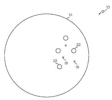
[0007] FIG. 1 depicts a cross-sectional view of an embodiment of a dissolvable
downhole tool disclosed herein;
[0008] FIG. 2 depicts a magnified partial cross-sectional view of a structure
of the
dissolvable downhole tool of FIG. 1 in a green state;
[0009] FIG. 3 depicts a magnified partial cross-sectional view of the
structure of the
dissolvable downhole tool of FIG. 1 in a forged state;
[0010] FIG. 4 depicts a magnified partial cross-sectional view of a structure
of an
alternate embodiment disclosed herein in a forged state; and
[0011] FIG. 5 depicts a cross-sectional view of an alternate embodiment of a
dissolvable downhole tool disclosed herein.
DETAILED DESCRIPTION
[0012] A detailed description of one or more embodiments of the disclosed
apparatus
and method are presented herein by way of exemplification and not limitation
with reference
to the Figures.
[0013] Referring to Figure 1, a cross-sectional view of an embodiment of a
dissolvable downhole tool, depicted in this embodiment as a tripping ball, is
illustrated at 10.
Alternate embodiments of the downhole tool include 10, ball seats and cement
shoes, for
example, as well as other tools whose continued downhole presence may become
undesirable. The downhole tool 10 includes a body 14 constructed of at least
two reactive
materials with this particular embodiment disclosing specifically two reactive
materials 18,
22. The first reactive material 18 being much more reactive than the second
reactive material
22. These reactivities being defined when the reactive materials 18, 22 are in
an environment
wherein they are reactive (as will be described in detail below), such as may
exist in a
downhole environment, for example. The body 14 is configured by the reactive
materials 18,
22 to cause the body 14 to dissolve in response to reaction of at least one of
the reactive
materials 18, 22. The reaction of the at least one reactive material 18, 22
causes dissociation
and subsequent dissolving of the downhole tool 10. The dissolving of the
downhole tool 10
removes any obstructive effects created by the presence of the downhole tool
10, as any
remnants of the body 14 can simply be washed away.
[0014] The reactive materials 18, 22 can be selected and configured such that
their
reactivity is dependent upon environments to which they are exposed. As such,
the reactive
materials 18, 22 may be substantially non-reactive until they are positioned
downhole and
exposed to conditions typically found in a downhole wellbore environment.
These conditions
CA 02762070 2011-11-15
=
WO 2010/135115 PCT/US2010/034543
include reactants, such as typical wellbore fluids, oil, water, mud and
natural gas, for
example. Additional downhole conditions that may be reactive with or affect
reactivity of the
reactive materials 18, 22 alone or in combination with the wellbore fluids
include, changes in
temperature, changes in pressure, differences in acidity level and electrical
potentials, for
example. These reactions include but are not limited to oxidation and
reduction reactions.
These reactions may also include volumetric expansion that can add mechanical
stress to aid
and accelerate the dissolving of the body 14. Materials that can be reactive
in the downhole
environment and thus are appropriate choices for either or both of the
reactive materials 18,
22 include, magnesium, aluminum, tin, tungsten, nickel, carbon steel,
stainless steel and
combinations of the aforementioned.
[0015] The reactive materials 18, 22 are configured in the body 14 to control
a rate at
which the first reactive material 18 (the more reactive of the two reactive
materials) reacts
thereby also controlling the rate at which the body 14 dissolves. This is in
part due to the
significant difference in reactivity between the first reactive material 18
and the second
reactive material 22. This difference is so significant that a rate of
reaction of the first
material 18 may be insignificant in comparison to a rate of reaction of the
second reactive
material 22. This relationship can allow an operator to substantially control
the time from
first exposure of the downhole tool 10 to a reactive environment until
completion of
dissolving of the body 14 with primarily just the second reactive material 22.
As such, the
reactive materials 18, 22 can be configured in relation to one another in
various ways, as will
be discussed below, to assure the time to dissolve is controlled primarily by
the second
reactive material 22.
[0016] Referring to Figures 2 and 3, the reactive materials 18, 22, as
illustrated, are
configured in this embodiment such that the time to dissolve is controlled by
the second
reactive material 22. Sinterable first particles 28 of the first reactive
material 18, and
sinterable second particles 32 of the second reactive material 22 are shown in
Figure 2 in a
green state and in Figure 3 in a forged state. The green state being defined
as after the
particles 28, 32 are thoroughly mixed and pressed into the shape of the body
14, but prior to
sintering. The forged state is after sintering and at a point where
fabrication of the downhole
tool 10 is complete. ln the forged state the first particles 28 are sealed
from direct exposure
to the downhole environment by sealing of adjacent second particles 32 to one
another,
including interstitial webbing 36 formed during the sintering process. This
sealing of the first
particles 28 prevents their reacting. A thickness 40 of the interstitial
webbing 36 is the
thinnest and weakest portion of the seal created by the sintering of the
second particles 32.
3
= CA 02762070 2011-11-15
=
WO 2010/135115 PCT/11S2010/034543
As such, a leak path through the seal will likely occur first at the
interstitial webbing 36 in
response to reaction and subsequent degradation of the second material 22.
Through control
of the sintering process the thickness 40 of the interstitial webbing 36 can
be accurately
controlled. Such control allows an operator to forecast the time needed to
degrade the
interstitial webbing 36 to the point that the first particles 28 begin to be
exposed to the
downhole environment and begin to react. Once the first particles 28 begin to
react the
additional time needed for the body 14 to dissolve is short.
[0017] The body 14 can be configured such that once reaction of the first
particles 28
has begun reaction of other nearby first particles 28 can be accelerated
creating a chain
reaction that quickly results in dissolving of the body 14. This acceleration
can be due to
newly reactive chemicals that are released by reactions of the first reactive
material 18, or by
heat given off during reaction of the first particles 28, in the case of an
exothermic reaction,
or by volumetric expansion of the reaction that mechanically opens new
pathways to expose
new first particles 28 to the downhole environment.
[0018] In an alternate embodiment, reactivity of the second reactive material
22 can
be so slow as to be considered fully non-reactive. In such an embodiment the
reaction rate of
the first reactive material 18 is controlled, not by the reaction rate of the
second reactive
material 22 (since the second reactive material is does not react) but instead
by sizes of
interstitial openings (not shown but would be in place of the interstitial
webbing 36 of the
previous embodiment) between adjacent sintered second particles 32 of the
second reactive
material 22. The small size of the interstitial openings limits the exposure
of the first
particles 28 of the first reactive material 18 that controls a reaction rate
of the first reactive
material 18.
[0019] Referring to Figure 4, an alternate embodiment of a sintered structure
110 is
illustrated. The sintered structure 110 includes sintered particles 112 having
an inner core
118 made of the first reactive material 18 and a shell 122 made of the second
reactive
material 22. In this embodiment, the first reactive material 18 is sealed from
the downhole
environment by the shell 122 made of the second reactive material 22.
Degradation of the
shell 122 in response to reaction of the second reactive material 22 causes a
breach of the
shell 122 and results in exposure of the first reactive material 18 to the
downhole
environment. All other things being equal, control of a thickness 140 of the
shell 122 can
determine the time from initial exposure of the tool 10 to the downhole
environment until
initiation of exposure, and subsequent reaction of the first reactive material
18, and
consequently the time for dissolving of the downhole tool 10.
4
= CA 02762070 2011-11-15
=
WO 2010/135115 PCT/US2010/034543
[0020] Alternate embodiments of structures contemplated but not specifically
illustrated herein include, sintering mixtures of particles with some
particles having multiple
reactive materials, such as the sintered particles 112, and some having just
one reactive
material such as the first particles 28 or the second particles 32. Still
other embodiments may
include particles having two or more shells of reactive materials with each
additional shell
being positioned radially outwardly of the previous shell.
[0021] Referring to Figure 5, another embodiment of a dissolvable downhole
tool,
depicted herein as a tripping ball, is illustrated at 210. The downhole tool
210 includes, an
inner portion 218, made of the first reactive material 18 and a shell 222 made
of the second
reactive material 22. The shell 222 sealingly encases the inner portion 218
thereby occluding
direct contact between the first reactive material 18 and the downhole
environment. The
shell 222 is configured to react with the downhole environment thereby
degrading the shell
222 resulting in exposure the first reactive material 18 of the inner portion
218 directly to the
downhole environment, and subsequent reaction therewith. Similar to the
process described
above, in reference to the downhole tool 10, reaction of the first reactive
material 18 causes
the dissolvable downhole tool 210 to dissolve.
[0022] Several parameters of the downhole tool 210 can be selected to control
the rate
of reaction of the second reactive material 22 and ultimately the exposure of
the first reactive
material 18 and the full dissolving of the downhole tool 210. For example, the
chemical
make up of the second reactive material 22, an amount of alloying of the
second reactive
materials 22 with other less reactive or non-reactive materials, density, and
porosity. As
described above a thickness 240 of the shell 222 can be established to control
a time lapse
after exposure to a reactive environment until a breach of the shell 222
exposes the first
reactive material 18 to the reactive environment. Additionally, an
electrolytic cell between
either the first reactive material 18 and the second reactive material 22 or
between at least one
of the reactive materials 18, 22 and another downhole component can be
established to create
an anodic reaction to effect the reaction rate and the associated time to
dissolve the downhole
tool 210.
[0023] The aforementioned parameters can be selected for specific applications
such
that the reaction is estimated to result in the downhole tool 10, 210
dissolving within a
specific period of time such as within two to seven days of being positioned
downhole, for
example. Such knowledge allows a well operator to utilize the downhole tool
10, 210 for a
specific purpose and specific period of time while not having to be burdened
by the presence
of the tool 10, 210 after usefulness of the downhole tool 10,210 has expired.
CA 02762070 2011-11-15
WO 2010/135115 PCT/US2010/03-1543
[0024] While the invention has been described with reference to an exemplary
embodiment or embodiments, it will be understood by those skilled in the art
that various
changes may be made and equivalents may be substituted for elements thereof
without
departing from the scope of the invention. In addition, many modifications may
be made to
adapt a particular situation or material to the teachings of the invention
without departing
from the essential scope thereof. Therefore, it is intended that the invention
not be limited to
the particular embodiment disclosed as the best mode contemplated for carrying
out this
invention, but that the invention will include all embodiments falling within
the scope of the
claims. Also, in the drawings and the description, there have been disclosed
exemplary
embodiments of the invention and, although specific terms may have been
employed, they
are unless otherwise stated used in a generic and descriptive sense only and
not for purposes
of limitation, the scope of the invention therefore not being so limited.
Moreover, the use of
the terms first, second, etc. do not denote any order or importance, but
rather the terms first,
second, etc. are used to distinguish one element from another. Furthermore,
the use of the
terms a, an, etc. do not denote a limitation of quantity, but rather denote
the presence of at
least one of the referenced item.
6