Note: Descriptions are shown in the official language in which they were submitted.
MODULAR CRYPT AND MODULAR CRYPT SYSTEM WITH NICHE SIDE WALL
[0001]
BACKGROUND OF THE INVENTION
Field of the Invention
[0002] This invention relates to an indoor or outdoor modular crypt structure
and, in particular,
to a crypt structure which minimizes the need to pour concrete to construct
the crypt structure.
Description of Related Art
[0003] Crypt structures, or alternatively mausoleums, are structures that
compnse a plurality of
chambers for the entombment of bodily remains and/or corpses. Normally, crypt
structures are
above-ground structures which are freestanding or located within an existing
building. The
exteriors of these structures are oftentimes covered with granite, marble or
other various finish
materials to make them aesthetically pleasing.
[0004] Crypt structures are generally constructed in situ by pouring concrete
into erected forms,
usually constructed of wood, to form the walls and chambers of the crypt
structure. This process is
expensive and time consuming. The forms are removed after the concrete has
cured. Oftentimes,
concrete can contain excessive voids which can compromise structural
integrity. Thus, skilled
laborers must usually be employed to ensure proper formation of the crypt
structure. Some
circumstances require that the concrete crypts are precast off-site. This
would require the
additional expenses associated with transporting and installing concrete
structures of great weight.
Special installation equipment, such as large trucks, cranes, or the like may
also be required to
properly install such constructions.
[0005] Some examples of modular crypt structures can be found in United States
Patent Nos.
4,048,772 to Gaul; 5,243,794 to Pikor; and 6,105,315 to Stoecklein et al. The
assemblies
disclosed in these patents require almost complete fabrication of the crypt
chambers and chamber
walls prior to erecting the resulting crypt structure at the installation
site, thereby still
necessitating significant expense.
1
CA 2762740 2018-02-28
CA 02762740 2011-12-23
[0006] Therefore, a need exists to provide a modular crypt structure which
overcomes the
above-described deficiencies.
SUMMARY OF THE INVENTION
[0007] One embodiment of the present invention is directed to a modular crypt
structure
comprising a first frame, at least one module insert comprising a plurality of
walls defining a
chamber having at least one open end, and a closure panel. The insert is
positioned within
the first frame and the chamber adapted to receive bodily remains, which may
be contained
within a casket. The closure panel is attached to the first frame at an end
adjacent to the at
least one open end of the insert. The module insert may include both one open
end and one
closed end. The first frame may comprise a plurality of horizontal bars
vertically aligned
with one another, a plurality of vertical bars horizontally aligned with one
another, and a
plurality of support beams. The horizontal bars may intersect the vertical
bars and the
support beams may intersect the horizontal bars in a horizontal plane, thereby
forming a
platform. The module insert may then be positioned on the resulting platform.
The crypt
module may also comprise a crypt sealing cap, which is attached to the module
insert at an
end adjacent to the at least one end of the chamber. Additionally, the modular
crypt structure
may comprise a plurality of module inserts. The module inserts may each
comprise a
plurality of walls defining a plurality of chambers having at least one open
end, wherein the
inserts are situated within the first frame, and the chambers function as
crypt modules for the
insertion of bodily remains. The modular crypt structure may also comprise a
trim plate
which is attached to a bottom portion of the frame.
100081 In other embodiments, the frame may comprise a metal, such as aluminum,
the
module insert may comprise a plastic, fiberglass, polymer material, or a
metal, and the
closure panel may comprise marble or granite.
[0009] In one embodiment of the present invention, the modular crypt structure
comprises
an anchor assembly for attaching the closure panel to the frame. The anchor
assembly may
secure the periphery of the closure panel to the frame. The anchor assembly
may comprise
an anchor assembly body, a spring-loaded flange, an extension attached to the
anchor
assembly body and defining a hole therein, at least one bolt, a rosette
defining a hole therein,
and a screw. The bolt secures the anchor assembly body to the frame, and the
screw extends
through the rosette hole and the extension hole, such that the screw secures
the rosette to the
extension. The closure panel rests on a top surface of the extension, and the
spring-loaded
flange biases the rear surface of the closure panel such that the front
surface of the closure
CA 02762740 2011-12-23
panel is biased against the rosette. The anchor assembly may also comprise
bronze and/or
stainless steel.
[0010] Yet another embodiment is directed to a modular crypt structure which
comprises a
second frame. The second frame may be positioned such that a back end of the
second frame
is adjacent to a back end of the first frame. The first frame and second frame
may also be
integrally formed. In these embodiments, the module insert may comprise a
second open end
and extend through the first and second frames. Alternatively, this embodiment
may
comprise at least two inserts, each comprising a plurality of walls defining
chambers having
at least one open end. A first insert is positioned within the first frame
with the at least one
open end located at an end of the first frame opposite the back end of the
first frame. A
second insert is positioned within the second frame with the at least one open
end located at
an end of the second frame opposite the back end of the second frame. The
chambers are
adapted to receive bodily remains or portions thereof. A second closure panel
may be
attached to the second frame at an end opposite the back end of the second
frame.
100111 Further, the present invention is directed to an embodiment comprising
a roof and
at least two walls. A first wall may be positioned parallel to a first side of
the first frame, and
a second wall may be positioned parallel to the second side of the first
frame. The roof may
be positioned above the frame and supported by the first and second walls such
that the first
frame is surrounded by the roof and walls. The modular crypt structure may
also comprise a
plurality of wall support bars. The wall support bars may be positioned on the
first and
second sides of the frame, such that they bias an inside surface of the first
and second wall.
Alternatively, when the frame comprises a plurality of vertical bars, the roof
may extend
across the width and length of the frame being supported by and secured
directly to the
vertical bars.
(0012I One embodiment of a modular crypt system may include a crypt frame
having a
first side and a second side; at least one module insert, the insert
comprising a plurality of
walls defining a chamber having at least one open end, wherein the insert is
positioned within
the crypt frame and the chamber is adapted to receive bodily remains or
portions thereof; a
closure panel, the closure panel being attached to the crypt frame at an end
of the crypt frame
adjacent to the at least one open end of said chamber; and a first niche side
wall positioned
parallel to at least one of the first side and the second side of the crypt
frame. The first niche
side wall includes a side wall frame attached to at least one of the first
side and second side of
the crypt frame; a niche insert; and a niche closure panel. The niche insert
has a closed end
and an open end, and is positioned in the side wall frame such that the closed
end faces
3
CA 02762740 2011-12-23
toward the crypt frame and the open end faces away from the crypt frame. The
niche insert
defines a plurality of niches accessible from the opened end of the niche
insert and adapted to
receive bodily remains. The niche closure panel is attached to the side wall
frame adjacent
the open end of the niche insert closing the plurality of niches. The niche
insert may also
include a plurality of internal niche walls defining the plurality of niches.
The internal niche
walls may be intersecting vertical and horizontal walls. The niche side wall
frame may
include a plurality of horizontal bars vertically aligned with one another and
a plurality of
vertical bars horizontally aligned with one another, with the horizontal bars
intersecting the
vertical bars. The niche insert may include a flanged edge positioned around
the periphery of
the open end of the niche insert. The flange edge may engage the front surface
of the
horizontal and vertical bars. The modular crypt system may also include a
plurality of niche
inserts and/or a plurality of niche closure panels.
100131 Additionally, a second niche side wall may be provided such that a
niche side wall
is provided on each of the first and second sides of the crypt frame. The
second niche side
wall includes a second side wall frame attached to a side of the crypt frame;
a second niche
insert; and a second niche closure panel. The second niche insert has a closed
end and an
open end and is positioned in the side wall frame such that the closed end
faces toward the
crypt frame and the open end faces away from the crypt frame. The second niche
insert
defines a plurality of niches accessible from the open end of the niche insert
and adapted to
receive bodily remains. The second niche closure panel is attached to the side
wall frame
adjacent the open end of the niche insert closing the plurality of niches.
10014] An embodiment of a modular crypt system may also include a roof
positioned
above the crypt frame and supported by the first niche side wall and/or the
second niche side
wall. The roof may also be supported by and secured to vertical bars of the
crypt frame, the
first side wall frame, and the second side wall frame.
100151 Lastly, other embodiments of the present invention are directed to
methods for
constructing a modular crypt and for encapsulating bodily remains. These
methods may
comprise the steps of erecting a frame; providing at least one module insert;
configuring the
insert to define a chamber having at least one open end adapted to receive
bodily remains or
portions thereof; positioning the module insert in the frame; and closing the
crypt module at
an end associated with the at least one open end of the module insert. The
methods may also
comprise attaching a closure panel to the frame at an end of the frame
associated with the at
least one open end of the chamber. Further, walls and a roof may be provided
around the
frame. The method for encapsulating bodily remains may further comprise
inserting bodily
4
CA 02762740 2011-12-23
remains or portions thereof into the crypt module before closing the crypt
module and
providing a sealing cap in the chamber near the open end of the chamber. Both
methods may
comprise providing a plurality of vertical bars, horizontal bars and support
beams; aligning
the vertical bars horizontally and the horizontal bars vertically in an
intersecting manner;
forming a platform by arranging the support beams in a horizontal plane with
the horizontal
bars such that they intersect the horizontal bars; and positioning the module
insert on the
platform.
BRIEF DESCRIPTION OF THE DRAWINGS
100161 Fig. 1 shows a modular crypt structure with schematically represented
walls, roof,
and base;
100171 Fig. 2 shows a modular crypt structure frame with a module insert
therein and
attached closure panel;
100181 Fig. 3 shows a perspective view of a frame assembly;
100191 Fig. 4 shows a bottom view of a platform formed by a frame assembly;
100201 Fig. 5 shows a module insert construction;
100211 Fig. 6 shows an anchor assembly;
100221 Fig. 7 shows a perspective view of a closure panel which is attached to
a frame;
100231 Fig. 8 shows two frame assemblies in a back-to-back orientation;
100241 Fig. 9 shows a module insert in conjunction with a crypt sealing cap;
100251 Fig. 10 shows an elongated frame assembly;
100261 Fig. 11 shows a frame assembly with a roof connected directly to the
frame.
[00271 Fig. 12 shows a front plan view of a niche side wall frame;
100281 Fig. 13 shows a perspective view of a niche insert for a niche side
wall assembly;
10029) Fig. 14 shows a top cross-sectional view of a niche side wall assembly;
[0030] Fig. 15 shows a perspective view of a modular crypt system having a
niche side
wall attached to a side of a modular crypt frame assembly;
[0031] Fig. 16 shows a perspective view of a modular crypt system having a
niche side
wall attached to a side of a modular crypt frame assembly with a roof; and
100321 Fig. 17 shows a front plan view of a modular crypt system having two
niche side
walls attached.
CA 02762740 2011-12-23
DESCRIPTION OF THE PREFERRED EMBODIMENTS
100331 In the following Description of the Preferred Embodiments, "crypt
module" is a
chamber, vault, or another space defined within a crypt structure or mausoleum
for
encapsulating and/or entombing bodily remains.
[0034] "Module insert" is a piece of material which defines a crypt module
within a frame
according to the present invention. The module insert may be a flexible or a
rigid material. It
may comprise plastic, a polymer, fiberglass, or any material sufficient to
encapsulate and/or
entomb bodily remains.
[0035] "Bodily remains" refers to deceased persons and/or animals, human
and/or animal
corpse or corpses, portions of corpses and/or deceased persons, cremated
remains, or any
combination thereof, either enclosed in a casket and/or coffin or not.
[0036] For purposes of the description hereinafter, spatial orientation terms,
if used, shall
relate to the referenced embodiment as it is oriented in the accompanying
drawing Figs. or
otherwise described in the following detailed description. However, it is to
be understood
that the embodiments described hereinafter may assume many alternative
variations and
embodiments and that the specific embodiments illustrated in the accompanying
drawing
Figs. and described herein are simply exemplary and should not be considered
as limiting.
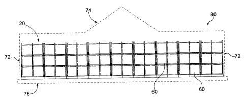
[0037] Fig. 1 shows an embodiment of the present invention, wherein a modular
crypt
structure 80 comprises a frame 20, which defines spaces, or alternatively
crypt modules 60,
for insertion of bodily remains. Frame 20 sits atop a base 76, and is covered
by a roof 74,
which is supported by walls 72. A crypt module 60 is formed by placing a
module insert 30
within frame 20, as indicated in Fig. 2. Module insert 30, which is shown in
Fig. 5, includes
walls 34 with outside surfaces 32 and inside surfaces 36. Walls 34 define a
chamber 35
having a chamber opening 37 at an end of module insert 30. Generally, an end
of module
insert 30 opposite chamber opening 37 is sealed, as represented by rear wall
surface 38 in
Fig. 2. Chamber 35 functions as crypt module 60 for insertion of bodily
remains or portions
of bodily remains when module insert 30 is placed within frame 20. Crypt
module 60 may
also be closed by attaching a closure panel 50 having front face 52, such as a
stone crypt
front, to an end of frame 20 adjacent to chamber opening 37 of module insert
30, thereby
encapsulating the bodily remains.
100381 As shown in Fig. 3, frame 20 comprises a plurality of vertical bars 22
horizontally
aligned and a plurality of horizontal cross bars 24 vertically aligned.
Additionally, frame 20
may comprise a plurality of support beams 26 which are vertically aligned.
Cross bars 24
are perpendicularly oriented to and intersect vertical bars 22 in a vertical
plane. As shown in
_
6
CA 02762740 2011-12-23
Figs. 3-4, when cross bars 24 and support beams 26 intersect and are
perpendicularly oriented
in a horizontal plane, cross bars 24 and support beams 26 form a platform 25
for supporting
module insert 30. Cross bars 24 may be attached to vertical bars 22 via nuts
and bolts at
joints 21, and cross bars 24 and support beams 26 may be welded at joints 23.
Alternatively,
horizontal cross bars 24, vertical bars 22 and support beams 26 may be
integrally formed.
However, any means of attachment sufficient to support module insert 30 are
contemplated.
Moreover, frame 20 may comprise any material or combination of materials
sufficient to
support the weight of bodily remains, and preferably comprises a metal, such
as steel or
aluminum. The vertical bars 22 may, for example, comprise 2 inch by 5 inch
tube aluminum
and horizontal cross bars 24 and support beams 26 comprise 1.5 inch by 2 inch
tube
aluminum.
100391 As noted above and as shown in Fig. 5, module insert 30 comprises walls
34 having
outside surfaces 32 and inside surfaces 36, wherein walls 34 form a chamber 35
having
chamber opening 37. Module insert 30 is then placed within frame 20 on top of
and
supported by platform 25, as shown in Fig. 2. In this configuration, chamber
35 of module
insert 30, functioning as a crypt module 60, may receive bodily remains.
Typically, the
bodily remains take the form of a corpse encapsulated within a casket and/or
coffin; however,
crypt module 60 may receive other forms of bodily remains, such as cremated
remains.
Frame 20 may comprise a plurality of platforms 25, as indicated in the
embodiments
represented by Figs. 2-3. As such, a plurality of module inserts 30 may be
placed within
frame 20. Module insert 30 may comprise any material sufficient to receive and
retain bodily
remains, such as a plastic material, a polymer material, fiberglass or a
metal, for example
aluminum.
100401 When module insert 30 or a plurality of module inserts 30 have been
placed within
frame 20, crypt module 60 or a plurality of crypt modules 60 may be sealed by
attaching a
closure panel 50 or a plurality thereof to an end of frame 20 adjacent chamber
opening 37, as
shown in Fig. 2. As illustrated, front face 52 of closure panel 50 may be
larger than the
chamber opening 37 of module insert 30, thereby allowing closure panel 50 to
completely
conceal chamber opening 37. The closure panel 50 biases and is attached to a
front side of
frame 20. A crypt module 60 may also comprise a crypt sealing cap 55, as shown
in Fig. 9.
A crypt sealing cap 55 closes chamber 35 at chamber opening 37, thereby
encapsulating the
bodily remains prior to attaching closure panel 50 to frame 20. A crypt
sealing cap 55 may
comprise a fluid-tight material for preventing leakage of fluid into and/or
out of crypt module
60. In the embodiment shown in Fig. 9, the crypt sealing cap 55 comprises a U-
shaped cap,
7
CA 02762740 2011-12-23
having a concave surface 53, wherein external surfaces of lips 57 of concave
surface 53 of
sealing cap 55 contact inside surfaces 36 of module insert 30, thereby fluidly
sealing crypt
module 60. Line 51 indicates the depth of crypt sealing cap 55 within chamber
35.
[0041] Figs. 2 and 7 show a closure panel 50 attached to both frame 20 and a
trim plate 54,
which is attached to frame 20 at a bottom portion thereof. Trim plate 54 may
be biased by a
base plate 28 shown in Fig. 7. Base plate 28 biases a rear face of trim plate
54, thereby
providing a stable backing for trim plate 54. A plurality of base plates 28
may extend around
the entire perimeter of frame 20 or a portion thereof for supporting a
plurality of trim plates
54 along the sides and front and back ends of frame 20. Closure panel 50 and
trim plate 54
may comprise a stone material, such as granite or marble to provide an
aesthetically pleasing
appearance.
[0042] In one embodiment, closure panel 50 and trim plate 54 are secured to
frame 20 by
an anchor assembly 40. Referring to Fig. 6, the anchor assembly 40 may include
nuts 44,
bolts 42, spring-loaded flanges 43, rosette 46 and extension 47. In one
embodiment,
extension 47 is alternatively referred to as a slide, which is removably
attached to the body of
anchor assembly 40 by sliding thereon. Extension 47 includes top surface 45
and a hole 41.
Rosette 46 also may include hole 49. Anchor assembly 40 is secured to frame 20
near joints
21, as shown in Figs. 2 and 7, by nuts 42 and bolts 44. Referring to Fig. 7,
anchor assembly
40 may secure closure panel 50 at a periphery of the closure panel 50 near its
corners.
Closure panel 50 rests on, and is thereby supported by, top surface 45 of
extension 47.
Rosette 46 biases a front face 52 of closure panel 50, and is secured by
inserting screw 48
through hole 49 of rosette 46 and hole 41 of extension 47. A spring-loaded
flange 43 biases a
rear surface of closure panel 50 pushing closure panel 50 forward against
rosette 46, thereby
biasing front face 52 against rosette 46 and securing closure panel 50 in the
fore and aft
directions. A single anchor assemble 40 may secure up to four closure panels
50, two
supported on top surface 45 of extension 47 and two below extension 47, the
spring-loaded
flanges 43 and rosette 46 biasing corners of a rear surface and the front face
52, respectively,
of each closure panel 50. The anchor assembly 40 may comprise an aesthetically
pleasing
material, such as bronze and/or stainless steel, for example.
10043] Referring to Fig. 8, an alternative embodiment of the described
invention comprises
a second frame 20a. In this embodiment, frames 20 and 20a are provided in
tandem with
back ends 27 and 27a oriented adjacent to one another. In this configuration,
a modular crypt
structure 80 is provided having two opposite ends, wherein module inserts 30
and 30a may be
placed within frame 20 and second frame 20a, respectively, thereby forming two
crypt
8
CA 02762740 2011-12-23
modules 60 and 60a, back to back. Closure panels may then be attached to
frames 20 and 20a
to seal respective crypt modules 60 and 60a. Alternatively, two crypt modules
60 and 60a
may be provided back to back in a single integrally formed elongated frame 20,
such as that
shown in Fig. 10. Additionally, module insert 30 or 30a may be formed such
that it
comprises two opened ends and extends through both frames 20 and 20a,
supported by
platforms 25 and 25a, respectively, as shown in Fig. 8, or through elongated
frame 20, as
shown in Fig. 10, thereby providing a crypt module 60 for the insertion of
bodily remains of
at least two persons.
[0044] A finished modular crypt structure 80 may comprise walls 72, a base 76
and a roof,
74 as shown in Fig. 1, respectively. The walls 72, base 76, and roof 74 may
comprise
aesthetically pleasing materials, such as granite, marble, brick, or stucco;
however, any other
materials sufficient for the user's needs are contemplated. Additionally, in a
finished crypt
structure 80, crypt modules 60 will include a closure panel 50. As such, frame
20 will not be
visible, as it is shown in Fig. 1. The walls 72 may run parallel to the sides
of frame 20 and in
some instances will run behind the rear of frame 20, thereby surrounding frame
20. Roof 74
may then be positioned above frame 20. When a wall 72 is erected and directly
attached to a
side of frame 20, frame 20 may include a wall support bar 29 or a plurality of
wall support
bars 29, as shown in Fig. 3. Wall support bar 29, which is attached to frame
20, provides
additional stability to wall 72 by biasing an inside face of wall 72. In such
constructions, the
walls may take the form of multiple plates or a continuous slab of material.
Wall support bar
29, as shown, is in a vertical position; however wall support bar 29 may be
positioned in
other manners, for example, horizontally. As indicated in Fig. 3, wall support
bar 29 may be
attached to frame 20 via flanges 19. When support bar 29 is positioned in a
horizontal
manner it may be directly connected to vertical bars 22. Both wall support bar
29 and flanges
19 may comprise 1.5 inch by 2 inch aluminum tube. Alternatively, a finished
modular crypt
structure 80 may be constructed and housed within an existing or concurrently
constructed
structure. For example, a frame 20, with accompanying module insert 30 and
closure panel
50, may be directly inserted into a block wall structure comprising for
example, concrete. A
modular crypt structure 80 may be also attached as an extension to a
preexisting structure.
Referring to Fig. 11, the roof 74 may be secured directed to the frame 20,
wherein roof 74
rests directly upon and is supported by vertical bars 22.
[0045] On-site, at a place of installation, frame 20 may comprise a plurality
of frames 20 in
tandem, as discussed above and shown in Fig. 8, side-by-side, as shown in Fig.
1, or in any
combination of arrangements. These arrangements may also comprise a single
integrally
9
CA 02762740 2011-12-23
formed frame 20, for example, in Fig. 1, frame 20 may be a single, elongated
frame, rather
than a plurality of frames, side-by-side. The frame 20 may arrive on-site as a
set of separate
components, for example, as pluralities of vertical bars 22, horizontal cross
bars 24, and
support beams 26, to be assembled at the place of installation. Alternatively,
the frame 20
may arrive on-site pre-constructed, ready for installation into a pre-existing
structure or for
erection of new walls around the frame 20. Upon arrival on-site, a frame 20,
may be grouped
in any desirable arrangement and secured to pre-existing frames. For example,
in Fig. 8,
frame 20 may arrive on-site, subsequently to frame 20a, which would have been
previously
constructed. Frame 20 may then be arranged and secured in tandem with frame
20a.
[00461 In yet another embodiment, a modular crypt system 180, as illustrated
in Figs. 12-
16, and like the embodiments discussed above, may include a frame 120 having
vertical bars
122 and horizontal cross bars 124 with module inserts 130 positioned within
frame 120 to
define crypt modules 160. Crypt module 160 may also be closed by attaching a
closure panel
150 having front face 152, such as a stone crypt front, to an end of frame 120
adjacent to
chamber opening 137 of module insert 130, thereby, encapsulating the bodily
remains. The
modular crypt system 180, however, also includes at least one niche side wall
200 positioned
parallel with a side of crypt module frame 120. The niche side wall 200
includes a frame
220, with a niche insert 230 defining a plurality of niches 235 for receiving,
for example,
cremated bodily remains and/or an accompanying um.
[00471 The niche side wall frame 220, as best illustrated in Figs. 15 and 16,
is positioned
along the side of and attached to modular crypt frame 120. As shown in Figs.
15 and 16,
niche side wall frame 220 may extend the entire length of the side of crypt
frame 120, or it
may extend only partially along the length of the side of crypt frame 120. In
the case where
niche side wall 200 does not extend the entire length of the side of modular
crypt frame 120,
as illustrated in Fig. 15, the portion of the crypt frame 120 side that does
not include niche
side wall 200 will generally comprise a wall, such as wall 72, illustrated in
Fig. 1.
[00481 Niche side wall frame 220 includes a plurality of vertical bars 222
horizontally
aligned and a plurality of horizontal cross bars 224 vertically aligned.
Referring to Figs. 15
and 16, the vertical bars 222 located at the rear portion of niche side wall
200 may be
positioned against vertical bars 122 of crypt module frame 220. These adjacent
vertical bars
122, 222 may be secured together, such as by nuts and bolts, by welding,
rivets, or any other
means sufficient to secure niche side wall frame 220 to modular crypt frame
120.
Alternatively, the top view of niche side wall frame 220 in Fig. 14 shows
vertical bars 222
connected to preexisting vertical bars 122 of modular crypt frame 120 via
horizontal cross
CA 02762740 2011-12-23
bars 224, as opposed to vertical bars 122, 222 being positioned against each
other. This will
generally be the case, i.e., bars 224 being connected to vertical bar 122,
such that niche side
wall frame 220 and modular crypt frame 120 share a vertical bar, when the
modular crypt
system 180, including the niche side wall 200 are installed as a single new
construction, as
opposed to retrofitting a preexisting modular crypt with a niche side wall
200, wherein
vertical bars 122, 222 may be positioned against each other. As shown, a
single vertical bar
222 on the back portion of niche side wall frame 220 may be necessary where
the niche side
wall 200 does not extend the entire length of the side of module crypt frame
120 in order to
secure niche side wall frame 220 to vertical bars 122 of modular crypt frame
120. As
illustrated, the single vertical bar 222 on the back portion of niche side
wall frame 220, in
conjunction with the preexisting vertical bar 122 of modular crypt frame 120
and horizontal
cross bars 224, form a corner recess at the portion of the side of modular
crypt frame 120 of
which niche side wall 200 does not extend across. Niche side wall frame 220
may also be
attached to modular crypt frame 120 at other locations, for example where
horizontal cross
bars 224 of niche side wall frame 220 contact cross bars 122 of modular crypt
frame 120.
100491 The cross bars 224 and vertical bars 222 of niche side wall frame 220
intersect and
are perpendicularly oriented in a vertical plane. As shown in Figs. 12 and 14-
16, horizontal
bars 224 extend across the front of frame 220 between adjacent vertical bars
222, and from
the front to back of frame 220 between adjacent vertical bars 222. Where cross
bars 224 and
vertical bars 222 intersect, cross bars 224 define a support shelf 225 for
receiving niche insert
230. Cross bars 224 may be attached to vertical bars 222 via nuts and bolts at
joints 221 or
may be welded at joints 221. Alternatively, horizontal cross bars 224 may be
integrally
formed with vertical bars 222. However, any means of attachment sufficient to
support niche
insert 230 are contemplated. Moreover, frame 220 may comprise any material or
combination of materials sufficient to support niche insert 230 and,
preferably, comprises a
metal, such as steel or aluminum. The bars 222, 224 may, for example, be
constructed of
tube aluminum.
100501 As best shown in Fig. 13, the niche insert 230 includes a plurality of
side walls 234
and defines a plurality of niches 235 for receiving, for example, cremated
bodily remains
and/or an accompanying urn. The niche insert 230 includes a closed end 237 and
an open
end 239. The niches 235 are defined at and accessible from the open end 239 of
the niche
insert 230. The niches 235 may, for example, be defined in niche insert 230 by
the presence
of internal, horizontal and vertical walls 232, 233 which are oriented
perpendicularly to one
another. The horizontal and vertical walls 232, 233 may be integrally formed
with side walls
11
CA 02762740 2011-12-23
234 or, alternatively, may be separate wall components attached to side walls
234 by, for
example, welding or mechanical fastening, such as by nuts and bolts. The open
end 239 of
niche insert 230 may also include a flange edge 236 positioned about the
periphery of the
open end 239 for attaching the insert 230 to the bars 222, 224 of niche side
wall frame 220.
The niche insert 230 may be constructed of the same material as the side wall
frame 220.
The niched insert 230 may be constructed of a metal, such as Aluminum or
steel, for
example.
[0051] Referring to Figs. 12, 15, and 16, the niche insert 230 may be inserted
into frame
220 and positioned on support shelf 225 defined by vertical and horizontal
bars 222, 224 with
the open end 239 facing away from modular crypt frame 120 and closed end 237
facing
toward modular crypt frame 120. The flange edge 236 provided around the
periphery of
niche insert 230 provides a means of securely fastening niche insert 230 to
niche side wall
frame 220. The flange edge 236 is positioned in abutment with a front face of
the vertical
and horizontal bars 222, 224, and may be secured to the vertical and
horizontal bars, 222,
224 mechanically, for example, by nuts and bolts extending through flange edge
236 and
horizontal and vertical walls 232, 233. However, the niche insert 230 may be
attached to
niche side wall frame 220 by any suitable means to fixedly secure the niche
insert 230 to
niche side wall frame 220.
[0052] When niche insert 230 has been adequately secured to niche side wall
frame 220,
niches 235 may be closed by attaching a closure panel 250 having a front face
252 to the
niche side wall frame 220 adjacent the open end 239 of niches 235. As
illustrated, front face =
252 of closure panel 50 may be larger or equal in size to the cross-sectional
area of niche
insert 230, thereby concealing all niches 235 defined in niche insert 230.
This may be the
case even where all of niches 235 of niche insert 230 do not contain bodily
remains, such as
cremated remains contained in an urn. The closure panel 250 may provide an
aesthetically
pleasing appearance by, for example, being constructed of a stone material,
such as granite or
marble. Fig. 14 shows closure panel 250 attached to niche side wall frame 220
from a top
view. Also shown in Fig. 14 is a closure panel 150 attached to modular crypt
frame 120 and
a wall extension 255 extending across a side and around the comer of niche
side wall frame
220. Wall extension 255, like closure panel 250, may be constructed of a stone
material, such
as granite or marble. When every support shelf 225 of niche side wall frame
220 is provided
with a niche insert 230, which is closed by closure panel 250, the closure
panels 250, in
conjunction with wall extension 255 and closure panels 150 of modular crypt
frame 120,
provide the appearance of a continuous granite wall around the periphery of
module crypt
12
CA 02762740 2011-12-23
system 180. The closure panel 250 and wall extension 255 may be secured to
frame via an
anchor assembly 240, which may operate in substantially the same manner as
anchor
assemble 40 described above with respect to Fig. 6. Additionally, as described
with respect
to the above discussed embodiments, a trim plate 254, shown in Figs. 15-17,
may be attached
to a bottom portion of niche side wall frame 220 below closure panel 250, in
the same
manner as trim plate 54 shown in Fig. 7. Trim plate 254, like closure panel
250, may be
constructed of a stone material, such as granite or nimble. At the comers of
frames 120, 220,
the modular crypt system 180 may include a side trim which is supported by a
trim angle
connected to vertical bar 222 or 122 located at the ends of the frames 120,
220. The side trim
outlines the corners of modular crypt system 180 and may close any gaps
between the closure
panels or wall extensions.
[0053] Referring to Fig. 16, the modular crypt system 180 may include a roof
174
extending across the top of both frames 120, 220 and supported by the vertical
bars 122, 222.
The roof may be directly secured to vertical bars 122, 222. Referring to Fig.
17, the crypt
structure may include two niche side walls 200, 200a positioned on and
attached to each side
of modular crypt frame 120. The roof 174 may extend across each of the modular
crypt
frame 120, and the niche side wall frames 220, 220a of niche side walls 200,
200a.
Alternatively, if a roof 174 takes the form of roof 74, as illustrated in Fig.
1, the roof 174 may
be supported by niche side walls 200, 200a only. If the niche side walls 200,
200a extend the
entire length of the sides of modular crypt frame 120, such as niche wall 200,
illustrated in
Fig. 16, then no unmemorialized side walls, such as walls 72 in Fig. 1, would
be required to
construct a complete modular crypt system 180. In this configuration, modular
crypt system
180 may take the form of a mausoleum having memorial faces, such as closure
panels 150,
250 on at least three of four sides. In the case when modular crypt frame 120
takes the form
of an elongated frame having crypt modules 160 on both first and second ends,
such as frame
20 of Fig. 10, modular crypt system 180, as shown in Fig. 17, would include
memorial faces
on all four sides. No unmemorialized side walls would be required to construct
modular crypt
system 180, thereby, providing for an inexpensive and aesthetically pleasing
mausoleum that
maximizes use of its space.
[0054] In any of the above-discussed embodiments, time and man-power are
significantly
reduced in comparison to that required to build a typical crypt structure.
There is no longer a
need to pour excessive amounts of concrete using wood forms to construct the
entire crypt
structure, including each crypt module. The time to construct a modular crypt
structure 80 or
a modular crypt system 180 on-site, according to the present invention, is
estimated to be
13
CA 02762740 2011-12-23
approximately one-third of the time required to construct and cure a typical
concrete crypt
structure. Additionally, with frames 20, 120, 220 comprising a lightweight
material, such as
aluminum for example, manufacturing and transportation expenses are reduced.
[0055] As noted above, while specific embodiments of the invention have been
described,
it will be appreciated by those skilled in the art that various modifications
and alternatives to
those details could be developed in light of the overall teachings of the
disclosure. The
presently preferred embodiments described herein are meant to be illustrative
only and not
limiting as to the scope of the invention which is to be given the full
breadth of the appended
claims and any and all equivalents thereof.
14