Note: Descriptions are shown in the official language in which they were submitted.
CA 02762791 2011-11-18
WO 2010/135484 PCT/US2010/035501
WIND TURBINE
TECHNICAL FIELD AND BACKGROUND OF THE INVENTION
100011 The present invention relates generally to a wind turbine and control
system for the wind
turbine, and, more particularly, to a wind turbine that may operate at
relatively low wind speeds while
still generating electricity.
[0002] Conventional wind turbines typically start to operate when the wind
speed is at or above 8
mph. This is due in part to the weight of the turbine blades and also in part
to the friction in the gears
between the turbine blade shaft and the generator. Therefore, current wind
turbines do not typically
harness energy from wind speeds of less 8 mph. Given that wind speeds below 8
mph represent a
significant component of the overall wind speed spectrum in the U.S. and,
elsewhere, the current wind
turbines overlook a significant potential source of energy.
[0003] Conventional wind turbines also tend to be relatively expensive;
difficult to install,
maintain, and operate; and not easily integrated into the electrical system of
a residential or small
business setting. Conventional wind turbines may also become damaged if the
wind speeds are
excessive.
SUMMARY OF THE INVENTION
[0004] The present invention provides a wind turbine that can harness energy
from low wind
speeds to generate electricity. Further, the wind turbine can be assembled
using relatively simple and
inexpensive components and, further, can be constructed so that it can be
portable and mounted on top
of existing structures. Additionally, the wind turbine may be configured so
that there is a significant
reduction in noise generated when the wind turbine is operating, even under
high wind speeds.
Optionally, the wind turbine may be adapted to harness energy wind from beyond
the outer periphery of
the wind turbine blades to further enhance the efficiency of the wind turbine.
[00051 In one form of the invention, a wind turbine includes a rotary shaft
having an axis of
rotation, a plurality of turbine blades supported for rotary motion about the
shaft, a plurality of magnets,
which are supported by and spaced outwardly from the axis of rotation and
outwardly from the rotary
shaft, and a coil. The blades are mounted to the shaft by a mount that is
radially inward of the magnets
wherein the magnets have an angular velocity of at least the angular velocity
of the blades. Further, the
coil is located outwardly from the magnets, and optionally such that the coil
surrounds the magnets.
[0006] In another form of the invention, a wind turbine includes a support and
a plurality of turbine
blades mounted for rotational movement relative to the support. Each of the
blades has a proximal end
inward of its distal end, with the distal end of each blade having a greater
width than its inward proximal
ends. Further, each blade has an asymmetrical cross-section which varies along
its length.
1
CA 02762791 2011-11-18
WO 2010/135484 PCT/US2010/035501
[0007] In yet another form of the invention, a wind turbine includes a support
and a plurality of
turbine blades mounted for rotational movement relative to the support. Each
of the blades has a
proximal end inward of its distal end, with the distal end of each blade
having a greater width than its
inward proximal ends, Further, each blade has an attack angle that varies
along its length, with the
greatest attack angle at its distal end and the smallest attack angle at its
proximal end.
[0008] According to yet another form of the invention, a wind turbine includes
a support and a
plurality of turbine blades rotatably mounted relative to the support. Each of
the blades is formed from
a flexible membrane, Optionally, blades on opposed sides of the support are
tied together so that the
radial forces acting on the opposed blades are balanced. Additionally, the
blades may be tied together
by an elastic member or a spring so that the blades may move away from the
support under high wind
conditions. Further, the blades may be configured to assume a more compact
configuration, e.g. fold or
compress, to reduce the surface area of the blade and hence the wind turbine's
solidity.
[0009] In another form of the invention, a wind turbine includes a turbine
wheel with a plurality of
wind turbine blades, which is mounted for rotation in a plane, and at least
one magnet extending
outwardly from the turbine wheel in a direction angled with respect to the
plane of rotation of the wind
turbine wheel.
[0010] According to yet another form of the invention, a wind turbine includes
a wind turbine wheel
with an outer rim and a plurality of stators, The stators are generally
aligned with at least a portion of
the outer rim of the wheel, with at least a portion of the stators being
radially inward of the outer
perimeter of the outer rim.
[0011] In any of the above turbine, the turbine blades may be formed from a
flexible membrane.
For example, each blade may include a frame with the flexible membrane applied
to the frame.
Suitable frames include metal frames, such as aluminum frames, stainless steel
frames, or the like.
Alternately, the frame may be integrally formed with the membrane. The
membrane can be formed
from a flexible sheet of material, such as a fabric, including nylon or a
KEVLAR , or from a polymer,
such as a plastic. The membrane is then mounted to the frame, for example, by
welds, stitches,
fasteners or the like,
[0012] Alternately, the blade may be molded from a moldable material, such as
plastic, including a
glass-filled nylon, polyethylene, a carbon fiber reinforced nylon, or KEVLAR .
For example when
molded, the blade may be formed with an integral frame. For example, the blade
may be molded with
an outer perimeter rim and a thin web that extends between the outer rim, with
the rim reinforcing the
thin web. Further, the web may be reinforced by ribs that extend across the
blade and optionally
between two opposed sides of the rim. In this manner, a separate frame may not
be needed.
[0013] In addition, the blades may be adapted to reduce the solidity of the
turbine. For example,
the turbine blades may be configured to assume a more compact configuration
when the wind speed
increases above a pre-determined wind speed. For example, the blades may be
configured to form an
2
CA 02762791 2011-11-18
WO 2010/135484 PCT/US2010/035501
opening in the blade that increases with an increase in wind speed above a
predetermined wind speed.
In one form the turbine blade is bifurcated with a bifurcated membrane, with
one portion of the
membrane being fixed and other separating from the fixed membrane in response
to the wind speed
exceeding the predetermined wind speed.
[0014] In further aspects, the wind turbines may include a spoked wheel with a
central hub and a
plurality of spokes extending outwardly from the hub, which then support an
annular ring or rim at their
outer distal ends, The turbine blades are then mounted to the spokes, In this
application, the magnets
may be mounted to the annular rim of the wheel.
[0015] According to yet further aspects, the magnets may be mounted to the rim
and extended
from the rim along radii of the spoked wheel frame so that they lie in the
same plane as the wheel. In
another form, the magnets can be mounted to extend in a direction angled from
the plane of rotation of
the wheel. For example, the magnets may be mounted to the rim in a generally
perpendicular
orientation relative to the wheel so that they may extend in a horizontal
direction around the axis of
rotation of the wheel.
[0016] In other aspects, the stator coil or stator coils are configured with a
generally U-shaped
cross-section with a channel. Further, the magnets extend into the channel so
that the coil straddles or
surrounds the magnets on at least two sides. Additionally, the coil may be
configured so that one leg of
U-shaped cross-section of the coil generates current that is additive with the
current generated in the
second leg of the U-shaped cross-section of the coil. In this manner, when a
magnet passes through
the coil, the magnet generates double the electricity in the coil than if the
coil was positioned at only one
side of the magnet.
[0017] In a further aspect, the stator coil or stator coils are configured to
extend at least partially
around the circumferential path of the magnets. Optionally, the coil or coils
may be extended around
the full circumferential path of the magnets.
[0018] Accordingly, the present invention provides a wind turbine that can
operate at low wind
speeds, for example at wind speeds that are below 8 mph, less than 6 mph, less
than 4 mph, and even
below 2 mph, for example, at about 0.3 mph.
[0019] According to other aspects, the present invention provides a wind
turbine and control
system that automatically controls the orientation of the wind turbine and the
generation of electrical
power therefrom in such a manner so as to avoid damage to the wind turbine and
to increase the
efficiency of the wind turbine system. The wind turbine system is easy to
install in residential and
similar type settings and may incorporate one or more conventional parts, such
as automobile batteries,
to reduce the cost of the overall system.
[0020] According to another aspect, a system for generating electricity from
wind is provided.
The system includes a wind turbine and a control subsystem for the wind
turbine. The wind turbine
includes a plurality of blades adapted to rotate about an axis and to thereby
generate an output voltage.
3
CA 02762791 2011-11-18
WO 2010/135484 PCT/US2010/035501
The wind turbine has an electrical impedance and the control subsystem has a
variable impedance
controlled by a controller. The controller extracts power from the wind
turbine in a pulsed manner by
changing the variable impedance of the control subsystem between levels that
are below and above the
electrical impedance of the wind turbine,
[00211 According to another aspect, a system for generating electricity from
wind is provided.
The system includes a wind turbine and a control subsystem. The wind turbine
includes a plurality of
blades adapted to rotate about an axis and to thereby generate an output
voltage. The control
subsystem extracts electrical power from the wind turbine in a substantially
continuous manner when
the wind speed is less than a wind speed threshold, and the control subsystem
extracts electrical power
from the wind turbine in a pulsed manner when the wind speed is greater than
the wind speed
threshold.
[0022] According to another aspect, a control system for a wind turbine having
a plurality of
blades adapted to rotate about an axis is provided. The control system
includes a first sensor, a
second sensor, a motor, and a controller. The first sensor determines wind
direction; the second
sensor determines wind speed; and the motor changes an orientation of the
rotational axis of the wind
turbine. The controller is in communication with the first and second sensors
and activates the motor
such that the axis aligns with the wind direction when the wind speed is less
than a threshold. The
controller further activates the motor such that the axis is misaligned with
the wind direction when the
wind speed is greater than the threshold.
[00231 According to another aspect, a system for generating electricity from
wind power is
provided. The system includes a wind turbine, a voltage sensor, a switching
converter-such as, but
not limited to-a buck converter, an inverter, a transfer switch, a battery,
and a controller. The wind
turbine includes a plurality of blades adapted to rotate about an axis and
generate a voltage output.
The voltage sensor measures the voltage of the output from the wind turbine.
The switching converter
is in electrical communication with the wind turbine voltage output and
reduces the voltage level of the
wind turbine voltage output. The inverter converts direct current into
alternating current, The transfer
switch selectively couples either an output of the inverter or a utility-
supplied source of electrical energy
to a distribution panel in the residence or business setting to which the wind
turbine is supplying
electrical energy. The controller is in communication with the voltage sensor,
the buck converter, the
battery, and the transfer switch. The controller monitors the charge level of
the battery and switches
the transfer switch to couple the utility-supplied source of electrical energy
to the distribution panel
when the charge level of the battery falls below a charge threshold and the
output voltage falls below a
voltage threshold.
[00241 According to other aspects, the second sensor may be an anemometer
physically spaced
away from the wind turbine blades, or it may be one or more sensors adapted to
measure a speed of
the plurality of blades. The controller may further activate the motor such
that the amount of
4
CA 02762791 2011-11-18
WO 2010/135484 PCT/US2010/035501
misalignment between the axis and the wind direction increases as the wind
speed increases above the
threshold. The voltage regulator may supply a regulated voltage to the
inverter and one or more
batteries. The blades of the wind turbine may have a profile that occupies a
relatively large portion of
the circular area defined by the rotation of the blades, such as 50% or more,
although other levels of
solidity may be used. The wind turbine itself may include a plurality of
magnets mounted adjacent an
outer end of the plurality of blades, The controller may be adapted to
automatically couple the battery
to the distribution panel upon detecting a loss of utility-supplied power. The
controller may also be
configured to monitor a charge level of the battery and prevent the battery
from experiencing a deep
cycle discharge except when the controller detects a loss in the utility-
supplied power. The controller
may re-charge the battery by applying a substantially constant current to the
battery until a threshold
level of charge is reached and thereafter supply a substantially constant
voltage to the battery after the
threshold level of charge is reached. The battery may be a conventional
automobile battery, or a
plurality of conventional automotive batteries electrically coupled together
in any suitable manner. The
control subsystem may change its electrical impedance in a pulsed manner that
alternates between
slowing the wind turbine down to a low speed threshold and allowing the wind
turbine to regain speed
up to an upper speed threshold, and which repeats in a like manner.
[00251 According to still other aspects, the controller may transmit
electricity generated by the
wind turbine directly to the inverter if the level of voltage generated by the
wind turbine exceeds a
voltage threshold. The inverter may convert direct current into alternating
current having a voltage of
substantially 120 volts so that the voltage may be supplied directly to
residences and business in North
American homes or small businesses. In other embodiments, the inverter may be
configured to convert
the direct current into alternating current having a voltage equal to the
customary household voltage
supplied to the residences of a particular country or geographical region
(e.g. 230V for European
residences). The controller may include a display panel that displays one or
more of the following: wind
speed, wind direction, battery charge, cumulative energy generated to date,
and voltage being
generated by the wind turbine.
[00261 These and other objects, advantages, purposes, and features of the
invention will become
more apparent from the study of the following description taken in conjunction
with the drawings.
BRIEF DESCRIPTION OF THE DRAWINGS
[00271 FIG. 1 is an elevation view of a wind turbine of the present invention;
[00281 FIG. 2 is a side end view of the turbine of FIG. 1;
[00291 FIG. 3 is an elevation view of another embodiment of the wind turbine
of the present
invention;
[00301 FIG. 4 is a side end view of the turbine of FIG. 3;
[00311 FIG. 5 is an enlarged view partial fragmentary view of the stator coil
of FIG. 4 illustrating
the magnet in the channel formed by the stator coil;
CA 02762791 2011-11-18
WO 2010/135484 PCT/US2010/035501
[0032] FIG. 6 is an elevation view of another embodiment of the wind turbine
of the present
invention with a spoked wheel;
[0033] FIG. 7 is an enlarged view of the wheel and magnet mounting
arrangement;
[0034] FIG, 8 is an enlarged view of the wind turbine blade mounting details;
[0035] FIG. 9 is an elevation view of the spoked wheel with the turbine blades
removed for clarity;
[0036] FIG. 10 is an enlarged view of one mounting arrangement of the magnet
to the rim of the
spoked wheel;
[0037] FIG. 11 is a similar view to FIG. 6 with the coil cover and blades
removed for clarity;
[0038] FIG. 12 is an enlarged view of the stator coil mounting arrangement;
[0039] FIG. 12A is a schematic drawing of the stator coils and their
interconnecting circuit;
[0040] FIG. 13 is another enlarged view of the stator coil mounting
arrangement and magnet
mounting arrangement;
[0041] FIG. 14 is an enlarged view of a turbine blade;
[0042] FIG. 14A is an enlarged view of the turbine blade frame;
[0043] FIG. 15 is an elevation view of another embodiment of the turbine
blade;
[0044] FIG. 15A is a side view of the turbine blade of FIG. 15;
[0045] FIG. 15B is an enlarge view illustrating the turbine blade of FIG. 15
mounted to the turbine
wheel;
[0046] FIG. 16 is an enlarged view of another embodiment of the turbine blade
that incorporates a
partial membrane mounted to the turbine blade frame;
[0047] FIG. 17 illustrates the turbine blade of FIG.16 with a second partial
membrane support
mounted to the frame for movably mounting a second partial membrane to the
frame;
[0048] FIG, 17A is a plan view of the membrane support of FIG. 17;
[0049] FIG. 18 illustrates the turbine blade of FIG. 16 with the second
partial membrane mounted
to the frame;
[00501 FIG. 19 illustrates the turbine blade of FIG. 18 with a biasing member
for biasing the
second partial membrane in a position that provides the maximum solidity to
the turbine blade;
[00511 FIG. 20 is a side end elevation view of another embodiment of the wind
turbine of the
present invention;
[00521 FIG. 21 is an enlarged view of the turbine wheel and magnet mounting
arrangements;
[0053] FIG. 22 is an enlarged view of the magnet mounting arrangement;
[0054] FIG. 23 is an enlarged partial view of the turbine blade wheel of FIG.
21 illustrating the
magnets and stator mounting arrangements;
[0055] FIG. 24 is an enlarged view of the another embodiment of the wheel and
stator mounting
arrangement;
[0056] FIG. 25 is an enlarged view of the stator coil and magnet mounting
details;
6
CA 02762791 2011-11-18
WO 2010/135484 PCT/US2010/035501
[0057] FIG. 26 is an elevation view of another embodiment of the wind turbine
of the present
invention;
[0058] FIG, 27 is a side elevation view of the wind turbine of FIG. .26;
[0059] FIG. 28 is an elevation view of the another embodiment of the wind
turbine of the present
invention incorporating a wind concentrator mounted to the windward facing
side of the wind turbine;
[0060] FIG. 28A is an enlarged fragmentary view of the stator coil assembly
and magnet
mounting details to the turbine wheel;
[0061] FIG. 28B is another enlarged fragmentary view of the stator coil
assembly and mounting
details;
[0062] FIG. 28C is an enlarged fragmentary view of the wind turbine frame and
mounting details
for the wind concentrator;
[0063] FIG. 28D is an enlarged fragmentary view illustrating the turbine
blades coupled together
by a tie support and of the wind turbine frame mounting details;
[0064] FIG. 29 is an enlarged fragmentary view illustrating a lateral support
or guide for the turbine
wheel;
[0065] FIG. 29A is an enlarged front elevation view illustrating another
embodiment of a lateral
support or guide;
[0066] FIG. 29B is a rear elevation view of the lateral support or guide of
FIG. 29A also illustrating
the magnet mounting details to the turbine wheel;
[0067] FIG, 30 is an elevation view of the cover of the wind turbine of FIG.
28;
[0068] FIG. 30A and 30B are perspective views of two sections of the cover of
FIG. 30;
[0069] FIG. 30C is a cross-section view of the cover of FIG. 30;
[0070] FIG. 31 is an elevation view of another embodiment of the wind
concentrator mounted to
the windward facing side of the wind turbine with optional stabilizers;
[0071] FIG. 32 is a schematic drawing of the wind turbine of the present
invention mounted on top
of a dwelling; and
[0072] FIG. 33 is a chart illustrating a Class 4 wind distribution.
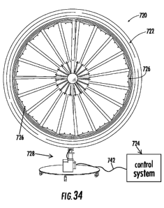
[0073] FIG. 34 is a front elevational view of an electrical generation system
including a wind-
turbine and a control system;
[0074] FIG. 35 is a side, elevational view of the wind-turbine of FIG. 34;
[0075] FIG. 36 is a front, elevational view of a residence and wind turbine
showing an illustrative
environment in which the electrical generation system may be used;
[0076] FIG. 37 is a diagram showing interconnections of various components of
a control system
for a wind turbine;
[0077] FIG. 38 is more detailed diagram of the control system of FIG. 37;
[0078] FIG. 39 is a detailed diagram of several internal components of a
charge controller;
7
CA 02762791 2011-11-18
WO 2010/135484 PCT/US2010/035501
[0079] FIG. 40 is a diagram of one embodiment of an electrical generation
system showing more
components than the view of FIG. 34;
[ooso] FIG. 41 is a diagram of the generator and generator control structures
of the system of
FIG. 40;
[0081] FIG. 42 is a diagram of the control system of the system of FIG. 40;
[0082] FIG. 43 is a chart showing various states that may be assumed by any of
the electrical
generation systems described herein;
[0083] FIG. 44A is a chart illustrating an arbitrary wind speed over a period
of time;
[0084] FIG. 44B is a chart illustrating power that may be generated by an
embodiment of the wind
turbine system disclosed herein when experiencing the wind speeds shown in
FIG. 44A; and
[0085] FIG. 44C is a chart illustrating pulsed power that may be generated by
another
embodiment of the wind turbine system disclosed herein when experiencing the
wind speeds shown in
FIG. 44A.
DESCRIPTION OF THE PREFERRED EMBODIMENTS
[00861 Referring to FIG. 1, the numeral 10 generally designates one embodiment
of a wind turbine
of the present invention, As will be more fully described below, wind turbine
10, as well as the other
wind turbines described herein, may be configured to operate at low wind
speeds. For example, the
wind turbines can be configured to operate at wind speeds that are below 8
mph, below 6 mph, below 4
mph, below 2 mph, for example, and even as low as about 0.3 mph. As will be
understood, this is
partially achieved by forming the wind turbine from low weight wind turbine
blades, and which therefore
have low inertia, and also by providing a gearless turbine. Although a
gearless turbine is initially
described, it should be understood that a geared turbine may also be used. In
addition, by mounting
magnets at a location with increased angular speed for a given wind speed over
conventional wind
turbines, increased electrical generation can be realized for the same wind
speed over a conventional
wind turbine and, further, can be realized by harnessing magnetic flux from
both sides of the magnet.
[0087] Referring to FIGS. 1 and 2, wind turbine 10 includes a frame 12 and a
base 14. Frame 12
and base 14 may be formed from suitable metal components, including aluminum
or stainless steel
components, depending on their application. In some applications composite
materials may also be
suitable. Frame 12 includes an outer perimeter or annular member 18 and brace
members 20, which
are supported by the perimeter member 18 and provide a mounting surface for
the wind turbine blade
assembly 22. Turbine blade assembly 22 includes a hub 24, such as a central
disk or plate, and a
plurality of turbine blades 26 that are mounted to hub 24 and extend radially
outwardly from hub 24,
which is mounted to frame 12, namely at brace members 20, by a shaft 22a.
Shaft 22a is journaled or
rotatably supported in brace members 20, for example, by bearings 22b, and
rotatably mounts hub 24
and blades 26 inwardly of perimeter member 18. Therefore, as noted above, the
connection between
8
CA 02762791 2011-11-18
WO 2010/135484 PCT/US2010/035501
the blade assembly and the supporting structure for the blade assembly is
gearless, though as noted a
gear may be included.
[0088] Also mounted to shaft 22a is a plurality of arms 28 that support
magnets 30. Suitable
magnets include nickel plated neodymium iron boron magnets. The size of the
magnet may vary but a
suitable size includes a 2 inch by 2 inch by 1/2 inch thick magnet, or may
include thicker magnets, such
as about 07", 0.8" or 1,0" thick magnets. As will be more fully described
below, magnets 30 are
positioned in relatively close proximity to a stator coil assembly 32, which
is supported in perimeter or
annular member 18 so that when the turbine blade assembly 22 rotates with
shaft 22a, arms 28 and
magnets 30 will similarly rotate to thereby induce current flow in the coils
of the stator coil assembly.
[0089] In the illustrated embodiment, turbine blade assembly 22 includes six
blades 26, which are
evenly spaced around shaft 22a. The diameter of the turbine blade assembly may
be varied depending
on the application, but for home use, including roof-top mountings, or even
commercial use, a diameter
of about 6 feet has been found to balance aesthetics and mounting logistics,
with electrical generation,
though larger or smaller sizes can be used. For other applications, including
for example marine
applications where the turbine is used to recharge a boat battery, for
example, the size may be smaller.
Additionally, the number of blades and magnets may be varied. As will be more
fully appreciated from
the following description, in addition to being able to make the wind turbine
compact in size, the weight
of the wind turbine may be significantly less than conventional wind turbines.
For example, the weight
may be less than 150 lbs., less than 125 lbs, or less than 100 lbs depending
on the size.
[00901 Further, the blades may be designed with aerodynamic profiles so as to
optimize energy
transfer from the wind to the rotating turbine blade system. For example, such
optimized aerodynamic
blade profile may employ tapering of the blade extremity to reduce the wind
shear and blade deflections
at high speeds. While suitable blades may include commercially available
blades, which are commonly
used in conventional turbines, the blades may alternately be rectangular bars
with a wind attack angle
between 5 and 100, which may offer more efficient operation at low wind
speeds and, further, can be
made at lower cost than conventional blades. Further, as will be more fully
described below the blades
may have a varying wind attack angle along its wind facing edge. It should be
understood that the
blade design selection and attack angle can be varied for a given turbine size
and wind speed operating
regime. Additionally, the shaft may be configured to offer minimal drag to the
wind and can be made of
an aerodynamic cross-sectional profile, including a round cross-section,
depending on the wind regimes
and weight considerations.
[0091] As shown in FIG. 2, magnets 30 are positioned so that they extend into
perimeter frame
member 18 and into the stator coil assembly. In this manner, when shaft 22a
rotates about its
rotational axis, the magnets will translate relative to the stator coil
assembly and thereby induce current
flow in the coils of the stator coil assembly. For further details of the
coils in the stator coil assembly,
reference is made to U.S. Patent applications serial numbers 12/138,818 and
12/698,640, both entitled
9
CA 02762791 2011-11-18
WO 2010/135484 PCT/US2010/035501
TURBINE ENERGY GENERATING SYSTEM, filed June 13, 2008 and February 2, 2010,
respectively,
by Imad Mahawili, Ph.D, the disclosure of both of which are hereby
incorporated herein by reference in
their entirety.
[0092] Arms 28 may be formed from a transverse rod 35, such as a metal rod,
including an
aluminum rod, which as noted is supported by shaft 22a of turbine blade
assembly 22. In this manner,
rod 35 is independent from turbine blades 26 but rotates in unison with the
respective blades by virtue
of rotation with shaft 22a, While only two arms or one rod is illustrated, it
should be understood that
more than one rod and one set of magnets may be used to double, triple or
quadruple the number of
magnets in the turbine. However, it should be noted that with an increased
number of magnets, the
weight of the rotating system is increased. As a result, with an increased
number of magnets, the wind
speed at which the turbine can start generating power may be increased.
[0093] By placing the magnets at the ends of the rod, the turbine blades are
allowed to deflect
under the high wind speeds without affecting the accuracy and placement of the
magnets within the
stator housing, which may simplify operation and extend electricity generation
performance. As will
more fully described below, however, the magnets may be supported at the
distal ends or tips of the
respective turbine blades by a rim or ring that is mounted to the turbine
blades, which would reduce the
blade deflections and which is more fully described below.
[0094] Referring to FIGS. 3 and 4, the number 110 generally designates another
embodiment of a
wind turbine of the present invention, Turbine 110, similar to turbine 10,
includes a frame 112 and a
base 114. Frame 112 and base 114 may be also be formed from suitable metal
components, including
aluminum or stainless steel components, or in some applications composite
materials may also be
suitable. In the illustrated embodiment, base 114 includes a fixed base
portion 114a and a rotatable
base portion 114b to which frame 112 is mounted. In this manner, the frame may
be repositioned, for
example, to reposition the turbine blades relative to the wind. Suitable
control systems for controlling
the position of turbine blade assembly and frame, as well as managing the
electrical energy generated,
are described in greater detail below.
[0095] Frame 112 includes an annular member 118 and two annular frame members
120a and
120b, which support annular member 118 on base 114, and more specifically on
rotatable base portion
114b. Frame members 120a and 120b also support turbine blade assembly 122 and,
similar to
members 20, include bearings 122b for supporting shaft 122a of turbine blade
assembly 122. Annular
member 118 also similar to the previous embodiment supports a stator coil
assembly 132, which is
supported radially outward of turbine blade assembly 122, and more
specifically radially outward of
turbine blades 126.
[0096] In the illustrated embodiment, frame members 120a and 120b comprise
wire fame
members formed from, for example, heavy gauge metal wire or small diameter
rods, such as aluminum
wire or rods, that form two concentric annular members 134a and 134b, which
support a plurality of
CA 02762791 2011-11-18
WO 2010/135484 PCT/US2010/035501
radial arms 136, Radial arms 136 in turn support bushings 122b that rotatably
support shaft 122a of
turbine blade assembly 122. As best seen in FIG. 4, the outer annular members
134a are then
mounted to movable base portion 114b of base 114, on for example a pair of
posts 114c. For example,
annular members 134a may be welded or otherwise fastened to posts 114c.
[00971 Annular member 118 is mounted between frame members 120a and 120b,
inwardly of
outer annular frame member 134a. Similarly to the previous embodiment, magnets
130 are mounted to
arms 128, which are mounted to shaft 122a, such that magnets 130 extend into
the stator coil assembly
132. In addition, with this configuration, magnets 130 have an angular
velocity greater than the angular
velocity of the hub that mounts turbine blade to shaft 122a and equal or
greater than the angular
velocity of the turbine blades, As noted in reference to the first embodiment,
the arms rotate with the
shaft 122a and are therefore rotated when the turbine blades rotate.
[0098 Referring to FIG. 5, annular member 118 is mounted to frame members 120a
and 120b by
fasteners and forms a stator coil assembly housing 140 for stator coil
assembly 132. Housing 140
comprises a generally annular channel-shaped member that may extend around the
full circumference
of the turbine wheel, as shown so that it fully encircles the path of the
turbine blades or just around a
portion of the path. For example, as will be more fully described below, the
stator coil assembly may
extend over only a portion of the path of the turbine wheel and may be
positioned at top most position
(12 o'clock position) of the blades or at the bottom most position (6 o'clock)
or in between.
[00991 Stator coil assembly housing 140 as noted has a generally channel-
shaped cross-section
and forms a channel 140a with an open side 14Db into which the magnets 130
extend. Housing 140 is
formed from a non-magnetic material, for example, plastic. The internal
spacing between the opposed
stator housing side walls is sized to minimize the gap 140c, for example an
air gap, between the
respective side wall of the stator housing and the respective magnet to reduce
the attenuation of the
flux induced by the rotating magnets.
[00100] The stator coil assembly 132 includes a plurality of coils formed from
a conductive wire,
such as copper or aluminum wire. For example, the coils may be made from a
double-loop copper wire
of gauges in a range of about ten to twenty-six, which supported inside
housing 140. The copper wire
gauge can be varied depending on the turbine size and power output design
requirements.
[001011 As described in the referenced application, the coils are formed from
a conductive wire that
is wound in a manner to increase the electric generation efficiency. This
achieved at least in part by
configuring the coil to straddle and extend over the two major surfaces of the
magnets. In this manner,
flux from both sides (major surfaces) of the magnet is harnessed. As described
in the above
referenced application, in order for the current to be additive, the coils
include two leg portions 150a
and 150b that straddle the magnet, which are interconnected by a turn or cross-
over portion 150c,
which cross-over portion allows the electrical current flow induced in both
legs 150a and 150b to be
additive. Further as best seen in FIG. 5, in order to optimize additive
current flow, the magnets are
11
CA 02762791 2011-11-18
WO 2010/135484 PCT/US2010/035501
positioned to extend far enough into the channel formed by the coil loops so
that they are aligned
between the coil loops and further spaced from the loop turn or twist area
(both from the upper and
lower coil turn areas). Also to facilitate the positioning of.the magnets in
the stator housing channel, a
pin 142 may be mounted to the end of the magnet or to the end of the arm,
which extends into a guide
channel 144 formed in housing 140,
[00102] In this manner, when the magnet or magnets pass by the respective
stator coil assembly or
assemblies, the magnetic flux caused by the moving magnet induces electrical
current to flow through
the respective coils. Further, by positioning the coil on either side of the
stator housing and, moreover
connecting the coils in a manner to have their electrical flow additive, the
turbine of the present
invention may provide an increased electrical output for a given rotation of a
shaft of a conventional
turbine. Furthermore, because the turbines of the present invention do not
need to use a gear box to
translate the rotary motion of the turbine blade shaft into rotary motion that
induces current flow, the
various turbines of the present invention may generate electricity at lower
wind speeds than
conventional turbines that incorporate gears or gear boxes. Though it should
be understood that a gear
or gear box may be coupled to the shaft for example to drive a generator to
provide an additional
source of electrical generation.
[00103] Referring to FIG. 6, the numeral 210 generally designates another
embodiment of a wind
turbine of the present invention. Turbine 210, similar to turbines 10 and 110,
includes a frame 212 and
a turbine blade assembly 222 supported by frame 212 on a base 214. Frame 212
and base 214 may
be also be formed from suitable metal components, including aluminum or
stainless steel components,
or in some applications composite materials. In the illustrated embodiment,
base 214 comprises a
movable base portion 214a and a frame mounting portion 214b, which is mounted
to movable base
portion 214a and to which frame 212 is mounted.
[00104] Frame 212 includes an annular cover 218, a post 219, brace frame
members 220, and a
turbine blade assembly 222. Brace frame members 220 mount cover 218 and
turbine blade assembly
222 to post 219, which in turn mounts cover 218, frame members 220 and turbine
blade assembly 222
to base 214. Cover 218 may be made from a metal sheet, such as an aluminum or
stainless steel
sheet, or a polymer, such as plastic, and also may be made from a composite
material, again
depending on the application.
[00105] In the illustrated embodiment, turbine blade assembly 222 includes a
wheel 250 (FIG. 9) to
which a plurality of turbine blades 226 are mounted. As best seen in FIG. 9,
wheel 250 includes a
central hub 250a and a plurality of radially extending spokes 252 that extend
from hub 250a at their
proximal ends and support a ring or rim 254 at their distal ends. As would be
understood, the hub, the
spokes, and the rim may also be formed from a metal material, such as aluminum
or stainless steel. As
best seen in FIG. 7, the spokes are offset at their connections to the hub but
are mounted at spaced
connections along a common annular path at the rim (see FIGS. 8 and 10) so
that one set or group of
12
CA 02762791 2011-11-18
WO 2010/135484 PCT/US2010/035501
spokes lies on one conical surface and the other lies on another conical
surface, similar to a bike wheel.
Stated another way, a first group of the spokes extend from a first set of
spaced connections at the hub
to a second set of spaced connections arranged along an annular path on the
rim. The second group.
of spokes extends from a third set of spaced connections at the hub to a
fourth set of spaced
connections along the same annular path as the second set of connections on
the rim, where the first
set of spaced connections is spaced from the third set of spaced connections
along the hub's axis of
rotation wherein the first group of spokes is offset from the second group of
spokes at the hub but
converge at the rim. As will be more fully described below, spokes 252 provide
mounting surfaces for
the turbine blades 226, which, in the illustrated embodiment, extend over a
high percentage of the
turbine's windward side, for example from about 50% to 70% of the windward
side of the turbine, which
is means the turbine has about a solidity from about 50% to 70%. As will be
described, below the
solidity of the turbine may be varied.
[001061 Referring again to FIG. 7, wheel 250 is supported by and journaled in
brace frame
members 220 by a shaft 250b, which extends through members 220 and is secured
thereto by nuts
250c and optional washers 250d. Members 220 are then mounted to post 219 by
brackets 260 and
posts 262, which receive fasteners 264, such as bolts, that extend through the
respective member 220,
which is proximate post 219, and into post 219. Therefore, as noted above, the
connection between
the wheel and the supporting structure for the wheel is gearless. Though as
noted a gear may be
included.
[001071 In the illustrated embodiment, and as best seen in FIGS. 10 and 11,
magnets 230 are
mounted to wheel 250 and, more specifically, to rim 254 by a bracket 266,
which is secured to rim 254
by a fastener or fasteners 268. Bracket 266 includes a mounting portion 270
that supports frame 272,
which extends radially outward from mounting portion 270, and which supports
magnet 230 therein.
Magnets 230 are mounted such that they extend outwardly and lie (their major
surfaces lie) in the same
plane as the wheel and further between the plane defined by the windward side
(side facing the
incoming wind) of the blades and the plane defined by the leeward side (side
facing the direction the
wind is blowing) of the blades, In the illustrated embodiment, wheel 250
includes ten magnets 230,
which are equally spaced around the wheel; however, it should be understood
that more or fewer
magnets may be used.
[001081 Referring to FIGS. 11 and 13, in the illustrated embodiment, stator
coil assembly 232 is
mounted to frame members 220 and is arranged around the outer perimeter of
wheel 250. Further, in
the illustrated embodiment, stator coil assembly 232 extends around only a
portion of the circumference
of the wheel and, further, is positioned at the top most blade position (12
o'clock). For example, stator
coil assembly 232 may extend over an arcuate span in a range of about 30 to
about 45 ; though, it
should be understood that it could be configured to extend over a greater
range, including the full 360
circumference of the wind turbine. Stator coil assembly 232 includes support
assembly 236, which is
13
CA 02762791 2011-11-18
WO 2010/135484 PCT/US2010/035501
mounted to frame brace member 220 and positioned in close proximity to ring
254. Further, as best
seen in FIG. 12, support assembly 236 consists of a pair of brackets 236a and
236b, which are spaced
apart and respectively mounted to frame members 220. Each bracket may comprise
a generally L-
shaped bracket and, further, include a pair of supports, for example in the
form of cylindrical posts 276a
that extend inwardly and support the stator coils 278a and 278b in a spaced
relationship to thereby
define a gap 280 between the respective stator coils. Stator coil assembly 232
is housed in cover 218
to thereby protect the stator coil assemblies and the respective magnets, as
the magnets move though
their circumferential path,
1001091 Referring to FIG. 12A, each pair of stator coils 278a and 278b are
interconnected by a
circuit 279, which may include a rectifier 279a to locally generate direct
current (DC) from each
individual coil. If rectifiers are not used then alternating current (AC) is
produced. This can be rectified
at a later state if needed. The electrical output can then be converted to a
standard 12 volt DC to
charge a small 12 volt DC car battery or a 120 volt alternating current
standard output voltage for direct
use,
[001101 Referring to FIGS. 14 and 14A, each blade 226 may be formed from a
frame 282, such as
a wire frame, and a flexible membrane 284, which may be formed from a fabric,
such as nylon,
polyester, or KEVLAR, or a thin sheet of a polymer material, such as plastic,
which forms the web of the
blade. Additionally, membrane 284 may be single-sided or two-sided-with one
side mounted to one
side of the frame, and the other side mounted to the other side of the frame.
Frame 282 (FIG. 14A) has
a generally isosceles trapezoid shape with two longitudinal sides 282a, 282b,
which are aligned along
radial axes of the wheel and are interconnected by transverse frame members
282c, 282d, and 282e.
For example, frame 282 may be formed from a metal rod, such as aluminum or
stainless steel or other
rigid but light-weight materials. Membrane 284 is secured to frame 282, for
example, by an adhesive,
welds, stitching, or fasteners or the like.
[00111] Blades 226 then are mounted to the respective spokes 252 along their
lengths by
fasteners, such as snaps, ties, or the like, including clips formed from a
spring material or an elastic
material to allow the blades to deflect parallel to the wind, for example at
high wind speeds. Further, as
best seen in FIG. 8, the proximal end (end nearest hub 250a) of each blade may
be secured to one
spoke by a clip, while the other, wider distal end of the blade may be coupled
to two spokes by two or
more clips to support the distal end of the blade but not necessarily anchor
the distal edge of the blade
to the wheel's rim, thereby leaving a gap or gaps between the blade's distal
edge and the rim of the
wheel, which allows the blade to flex. Optionally, blades 226 are removable
for repair and replacement.
[00112] When mounted to spokes 252, blades 226 are angled with respect to the
central plane of
the wheel. For example, blades 226 may be angled in a range, for example, from
2 degrees to 10
degrees including at about a 5 degree angle. At this angle it has been found
that the turbine generates
electricity at low speeds including as low as one mile per hour or less,
including 0.3 miles per hour.
14
CA 02762791 2011-11-18
WO 2010/135484 PCT/US2010/035501
Depending on the particular materials used, it also has been found that the
turbine will operate up to 40
or even up to 60 miles per hour, though it may be desirable to limit the speed
of the turbine. At the
higher speeds, as described in greater detail below, a microprocessor-based
control system may be
provided to change the direction of the turbine when the wind speed exceeds a
desired maximum wind
speed to thereby reduce the pressure on the blades. For example, the control
system may turn the
turbine into the wind to reduce the stress on the blades and on the wheel
mounting components. In
addition, as described below, the blades may be designed so that at higher
speeds they reduce their
surface area to reduce the solidity of the turbine and hence the speed of the
turbine wheel.
[001131 Referring to FIGS. 15, 15A, and 15B, the numeral 1226 designates an
alternate
embodiment of the turbine blade, In the illustrated embodiment, blade 1226 is
a molded blade and
similar to the previous embodiment is mounted to a spoke 252 at one side and
at its distal end to
another spoke. As best seen in FIG. 15B, each blade 1226 is mounted to a
respective spoke 252 along
one edge along its full length by fasteners, such as snaps, ties, or the like,
so that the blade is fully
supported along its length (either at spaced intervals or continuously) along
one edge by the wheel
spoke and therefore limit deflection at the full range of wind operation of
the wind turbine. However, the
blade may be mounted using a clip that is made of elastic or a spring material
to allow for blade
deflection generally parallel to the wind, for example at high speeds. This
may provide an automatic
safety limit for the turbine wheel rotation.
1001141 For example, blade 1226 may be molded from a moldable material, such
as a polymer,
including a plastic, or a fabric, such as nylon or KEVLAR. Suitable polymers
include glass-filled nylon,
polyethylene, or a carbon fiber reinforced nylon or the like. In order to
stiffen blade 1226, blade 1226
may be formed or provided with an outer perimeter rim 1228 and a web 1230 that
extends between the
outer rim. Rim 1228 may be formed from the same material as the web and simply
have a greater
thickness than the web to thereby in effect form a reinforcement frame, or rim
1228 may be formed from
an insert material, for example a metal frame, such as an aluminum frame, that
is molded with the
blade to impart greater stiffness while reducing the weight of the blade,
again thereby forming a frame
for the web.
[001151 For example, rim 1228 may be formed, for example by molding, from one
material which is
then inserted into the mold where the material forming the web is then
applied, for example, by injection
molding. The rim may also comprise a wire frame similar to the previous
embodiment, with the web
molded over the frame. Alternately, the blade may be molded using two
different materials using two-
shot molding. Further, the web 1230 may be reinforced by ribs 1232 that extend
across the face (either
windward or leeward side) of the blade and optionally between two opposed
sides of the rim 1228.
Ribs 1232 may have a greater thickness than web 1230 and may have the same,
lesser or greater
thickness as rim 1228. Again the ribs may be pre-formed and then inset into
the mold or may be
formed with the web, for example during molding, including using two shot
molding.
CA 02762791 2011-11-18
WO 2010/135484 PCT/US2010/035501
[00116] For a constant wind speed and wheel rotational speed, the blade root,
nearest the wheel
hub, experiences the slowest radial velocity. Whereas the blade tip, nearest
the wheel rim would
experience the maximum radial velocity. As best seen in FIGS. 15A and 15B,.
the blade angle of attack
may thus be varied along its length to accommodate efficient aerodynamic
energy conversion to
mechanical rotation of the wheel. For example, in the illustrated embodiment,
the attack angle of blade
1226 may decrease along its length, from its blade root (proximal end) 1226a
to its blade tip (distal end)
1226b. Therefore, the blade is asymmetrical. For example, the blade root 1226a
may have a very
steep attack angle, for example, in a range of 40 degrees to 50 degrees, or in
a range of 42 degrees to
48 degrees or approximately 45 degrees. The attack angle at the tip may range
from 0 degrees to 10
degrees, or in a range of 2 degrees to 5 degrees or approximately 3 degrees.
This is achieved by the
asymmetrical shape of the blade, which is concave on its windward side and
convex on its leeward
side. Given that the blade is formed form a thin web (except for its perimeter
rim and reinforcing
intermediate ribs), the blade's asymmetry can be formed from twisting the
blade during its formation
from its root end (end nearest to the hub) to its distal end (tip). Therefore,
as would be understood the
wind facing surface of each blade is not perpendicular to the incoming wind.
This design approach
increases the lift coefficient and minimizes the drag forces along the blade
length at various wind
speeds.
[00117] Referring to FIGS. 16-18, the numeral 226' designates an alternate
embodiment of the
blades in which the blades are configured to reduce the solidity of the
turbine wheel. As noted above
solidity refers to the amount of surface area defined by the circumference of
the blade tips covered by
the blades. For example, a 100% solidity would mean that the blades cover the
entire surface. For a
30% solidity, the blades cover 30% of the area. As will be more fully
described below, each blade 226'
may be adapted to self-adjust the solidity in response to increased wind
speeds.
[00118] Referring again to FIGS. 16-19, blade 226' includes a frame 282
similar to blade 226 and a
membrane 284', which is similarly formed from a flexible material, such as a
fabric or thin sheet of
flexible material or the like. In the illustrated embodiment, membrane 284'
comprises a primary, fixed
partial membrane and extends from the inward transverse member 282c of frame
282 to the medial
transverse member 282d and, therefore, only covers a portion of the frame 282.
In order to vary the
solidity, turbine blades 226' are configured to take advantage of the
centrifugal forces acting on the
turbine blade so that as the wind speed increases the solidity of the turbine
blade assembly decreases.
[00119] Referring again to FIGS. 17-19, turbine blade 226' includes a second
membrane 284a'.
Membrane 284a' is mounted about frame 282 and extends between intermediate
transverse frame
member 282d and outermost transverse frame member 282e. Further, membrane
284a' is mounted
such that its inwardly facing end 286a' is secured to a movable member 288' in
the form of a plate 290'.
Plate 290' includes with a pair of elongate guide openings 292', which allow
the plate 290' to be
mounted to side frame members 282a and 282b of frame 282 and slide along the
frame. In this
16
CA 02762791 2011-11-18
WO 2010/135484 PCT/US2010/035501
manner, the inwardly facing end 286a' of membrane 284a' may move relative to
frame 282 and, further,
compress toward its outer end 286b' to allow a gap to form between membranes
284a' and 284' to
thereby reduce the solidity of the respective turbine blade.
[00120] To control the bending or folding of membrane 284a', a pair of springs
are provided 294'.
Springs 294' are coupled on one end to outermost transverse frame member 282e.
and, further, are
extended along the respective side frame members 282a and 282b and coupled at
their distal ends to
transverse member 288'. Further, when mounted springs 294' are compressed so
that the respective
springs bias and urge transverse member 288' toward transverse member 282d of
frame 282 to
thereby maintain membrane 284a' in its extended state wherein the lower end
286a' abuts the outer
end 286' of membrane 284'. As the wind speed increases and the centrifugal
forces on the respective
membranes increase, transverse membrane 288' will compress springs 294' and
thereby allow
membrane 284a' to compress, for example by folding. For example, member 284a'
may be pleated so
that membrane compresses in a controlled fashion.
1001211 It should be understood that the ratio of the secondary membrane 284'
size relative to
membrane 284' size may be varied to vary the change in solidity of the blade,
Furthermore, the
stiffness of the respective springs may be varied to adjust the responsiveness
of the turbine blade.
Therefore, as described above, the blades of the turbine may be adapted to
reduce its solidity based on
the wind speed. Consequently, as the blades rotate, the blades may self open
based on the rpm.
[00122] Another option is to provide membranes formed from a material whose
porosity increases
with air pressure to thereby decrease its solidity.
[001231 Referring to FIG. 20, the numeral 310 designates another embodiment of
the wind turbine
of the present invention. Similar to the previous embodiments, wind turbine
310 includes a frame 312,
a turbine blade assembly 322 supported by frame 312 on a post 319, which
supports the frame on a
base 314. Similar to the second embodiment, base 314 comprises a fixed base
portion 314a but
supports post 319 for rotational motion about fixed base portion 314a. As best
seen in FIG. 20, post
319 is mounted in base 314 by bearings 314b and, further, may be driven by a
motor 314c housed in
base 314, which is controlled by a control system, which may be any of the
control systems described
below or another type of control system. Further, in the illustrated
embodiment, fixed base portion 314a
may include a base plate 314e and a plurality of support legs 314d which are
pivotally mounted to base
plate 314e to allow the height and footprint of the base 314a to be adjusted
as needed. Legs 314d may
be interconnected and reinforced by brace members 314f. Similar to the
previous embodiments, the
connection between the turbine blade assembly and the supporting structure for
the wheel is gearless.
[00124] Turbine blade assembly 322 may be of similar construction to turbine
blade 222 and,
therefore, reference is made to the previous embodiment for details of the
wheel 250 and blades 226
mounted to wheel 250. However, in the illustrated embodiment, magnets 330 are
mounted to wheel
250 with a perpendicular orientation to the rotational plane of wheel 250 so
that their major surfaces
17
CA 02762791 2011-11-18
WO 2010/135484 PCT/US2010/035501
extend in a generally horizontal direction. Magnets 330 extend into a stator
coil assembly 332, which
has a similar construction to stator assembly 232 with exception of its
orientation, which is rotated 90
degrees relative to the orientation of stator coil assembly 232 shown in the
previous embodiment. In
this manner, when wheel 350 experiences some wobble, the magnets will move
generally parallel to
the coils in the stator assembly and will generally maintain their gaps with
the respective coils.
[00125] Referring to FIG. 20, stator coil assembly 332 is similarly mounted at
the twelve-o'clock
position and, further, may extend over an arcuate portion of the circumference
of wheel 250 in a range
of about 30 degrees to 45 degrees (or may extend around the full circumference
of the wheel) and is
mounted to orient the gap 380 between the respective stator coils 378a and
378b in a generally
horizontal arrangement to thereby receive magnets 330 in their respective
horizontal orientation as
shown in FIGS. 20 and 21. Magnets 330 are also mounted to rim 254 of wheel 250
by brackets 366
and pins 366a, which support magnets 330 as noted above, but in a
perpendicular arrangement relative
to the rotational plane of wheel 250 (FIG. 22). Similar to the previous
embodiment, shaft 250b of wheel
250 is rotationally mounted to post 319 by a bracket 260' and, further, by an
additional support arm
319a, which is mounted to post 319 by a bracket 319b, as best seen in FIG. 21.
In this manner, both
ends of the rotational shaft 250b are supported. In the illustrated
embodiment, bracket 260' comprises
a flanged channel-shape member that mounts to post 319 by fasteners that
extend through its flanges.
[00126] Referring to FIGS. 26 and 27, the numeral 410 generally designates
another embodiment
of the wind turbine assembly of the present invention. Similar to the previous
embodiments, wind
turbine 410 includes a frame 412 that supports a wind turbine blade assembly
422 on a base 414.
Wind turbine blade assembly 422 includes a wheel 450 similar to wheel 250 to
which turbine blades
426 are mounted. For further details of wheel 450 and turbine blades 426
reference is made to the
previous embodiments. Frame 412 includes an annular member 418, which supports
a plurality of
stators coils 432 arranged around the circumference of wheel 450, which have a
channel-shaped
arrangement, as described in reference to the previous embodiments, to receive
magnets mounted to
the rim 454 of wheel 450. In this manner, as wheel 450 spins around its axis
450a, the magnets 430
mounted to rim 454 will induce electrical current flow in the stator coils
similar to turbine 210.
[00127] Frame 412 is supported on base 414 by a post 419 and a semicircular
frame member
414a, which mounts frame 412 to post 419. Frame member 414a is secured, for
example, by fasteners
414b to medial transverse frame members 420a and 420b of frame 412. Transverse
frame members
420a and 420b are joined at their opposed ends by transverse frame members 421
a and 421 b, which
provide a mounting surface for semicircular frame member 414a. Shaft 450b of
wheel 450 is then
supported in transverse frame members 420a and 420b, for example in bushings.
Again as noted
above, the components forming the frame and the base may be metal, polymeric
or composite
components.
18
CA 02762791 2011-11-18
WO 2010/135484 PCT/US2010/035501
[001281 Optionally, turbine 410 includes an auxiliary set of turbine blades
526, which are mounted
on blade arms 528, which are rotatably coupled to shaft 450b of wheel 450. In
this manner, when
wheel 450 rotates about its rotational axis 450a, blades 526 will rotate
simultaneously with wheel 450.
Blades 526, therefore, provide additional surface areas to increase the
rotational speed of the wheel
450.
[00129] Optionally, post 419 may be rotatably mounted to base 415 and,
further, rotated about
base 414 by the wind, For example, a wind vane 480 may be mounted to frame 412
so that the wind
will adjust the position of turbine 410.
[00130] Referring to FIG. 28, the numeral 610 generally designates another
embodiment of the
wind turbine of the present invention. Turbine 610 includes wind turbine wheel
250 with a plurality of
blades 626 mounted to wheel 250, a stator coil assembly 322, a base 614, and a
cover 650. Base 614
is similar to base 214 of turbine 210, which allows the wind turbine wheel 250
along with its blades to
change direction in response to the wind speed and direction, as described in
reference to the previous
embodiments.
[00131] In the illustrated embodiment, blades 626 are molded from a plastic,
such as described in
reference to blades 1226, and are similarly mounted to the spokes of the wheel
by fasteners, such as
clips. Also, similar to blades 1226, and as best seen in FIG. 28D, blades 626
may be mounted to the
spokes using clips that allow for deflection of the blades in response to the
wind speed exceeding a
preselected threshold. The longitudinal edge of each blade may be secured by
multiple clips to one
spoke, while the other longitudinal edge may be unrestrained but with the
distal end of the blade (at the
end of the unrestrained longitudinal edge) may be mounted by a clip to an
adjacent spoke, which
accommodates the asymmetrical shape of the blade. Thus, each of the blades'
distal edges (see e.g.
FIG. 28D) are therefore connected to the wheel by at least two clips (one at
the end of the restrained
longitudinal edge and the other at the unrestrained longitudinal edge) but
decoupled from the rim. In
this a manner, there is a gap between the distal edge of each blade and the
rim of the wheel, leaving
the blades with several degrees of freedom at their distal ends (as well as
along their unrestrained
longitudinal edges) so that the blades are allowed to flex or bend under high
wind speeds. For further
details of the wheel and the blades, reference is made to the previous
embodiment.
[00132] Like turbine 310, however, turbine 610 mounts its magnets so that they
extend outwardly
from wheel 250 in a direction angled to the plane of rotation of wheel 250
(see FIGS. 28A, 29, 29A, and
298) and into stator assembly 622 (FIGS. 28A and 28B). Stator assembly 622 is
of similar construction
to stator assembly 322 and is oriented so that its channel is in a horizontal
plane to receive the
generally horizontally arranged magnets.
[00133] Similar to the previous embodiments, wheel 250 is mounted to a post
619 (FIG. 28D) on
shaft 250b by a bracket 660 (similar to bracket 260'). Mounted to post 619 is
a plurality of transverse
frame members or rods 620a, 620b, 620c, which together mount stator assembly
622 to post 619.
19
CA 02762791 2011-11-18
WO 2010/135484 PCT/US2010/035501
Optionally, transverse support member 660a may be braced by diagonal support
members 620d and
620e. Post 619 and members 620a, 620b, 620c, 620d, and 620e may all be formed
from metal
components, including aluminum or stainless steel members, including
aluminum.or stainless steel
tubular members.
[00134] As best seen in FIG. 28B, stator assembly 622 includes a plurality of
stator sub-assemblies
622a that are mounted on a non-conductive plate 622b, which mounts stator
assembly 622 to
transverse support members 620a, 620b, and 620c with fasteners (see e.g. FIG.
28B).
[001351 Similarly, the leeward side (the side facing the direction in which
the wind is blowing) of
cover 650 may be mounted to the transverse support members 660a, 660b, and
660c by fasteners or
brackets (not shown), The windward side of cover 650 is mounted to a frame
620, which supports the
opposed end of shaft 250b in a central frame member 620f. Extending outwardly
from central frame
member 620f, which in the illustrated embodiment is in the form of a block,
are radially extending frame
members 620g, which in turn are coupled to cover 650. In this manner, post 619
supports wheel 250,
stator assembly 322, and cover 650.
[001361 Referring again to FIG. 28D, post 619 is mounted to the upwardly
extending post 614a of
base 614 to provide a rotatable mount for wheel 250. Post 619 is rotatably
mounted to post 614a by a
bracket 619a and bushing (not shown) and further is optionally driven about
post 614a by a driver 614c,
which is driven by a controller to change the orientation of the wind turbine
wheel, as described in the
detailed description of the controls systems below.
[00137] Referring to FIG. 28D, the inner end of each blade may be coupled to
the inner end of its
opposed blade, for example, by a rod, such as a metal rod, or wire member 600.
Member 600 includes
loop ends 600a for extending through openings formed in each respective blade
and thereby engaging
each respective blade. It should be understood that other suitable mounting
methods may be used.
Members 600 therefore tie opposed blades together to balance the centrifugal
forces generated at the
blades and reduce the stresses on the shaft. It should be understood that in
any of the wind turbine
described above, the blades on opposed sides from the hub may be tied
together, for example, by the
tie support, such as rod or wire member 600(see e.g. FIG. 6), which is coupled
on one end to one blade
and then coupled at its opposite end to the other, opposing blade.
1001381 'Further, because blades 226, 1226, 226', 426 are each configured so
that their outer ends
have a greater expanse than at their inner ends, the stresses at the
rotational shaft may be further
reduced. When this is combined with balancing of the centrifugal forces by way
of members 600, the
stress on the shafts of the respective turbines due to the centrifugal forces
normally generated at a wind
turbines blades can be drastically reduced, if not effectively eliminated.
[00139] Optionally, the tie supports may be formed from a material that can
extend or stretch to
allow the blades to compress as described above in reference to the blades
with the bifurcated webs,
while still balancing the centrifugal forces. For example, the tie supports
may be made from an
CA 02762791 2011-11-18
WO 2010/135484 PCT/US2010/035501
elastomeric material or incorporated a spring, such as a spring integrated
into or formed in the rod or
wire, for example.
[00140] In addition to balancing the centrifugal forces on the blades, wind
turbine 6.10 may also
balance the centrifugal forces on the magnets. For example, in the embodiment
where the magnets
are orthogonally oriented in relation to the rotational plane of the wheel,
additional rods 602 (FIGS. 22
and 24) may be extended through the wheel, with their distal ends, e.g.
threaded distal ends, anchored
in the magnet mounting brackets of opposed magnets (see FIG. 24) by for
example nuts. Alternatively,
the ends of the rods may be welded to the respective brackets or formed with
the respective brackets.
[00141] As best understood from FIG. 29, each of the respective wind turbines
may incorporate a
guide that provides lateral support to the wheel or frame to reduce vibration
or wobbling, to thereby
reduce the wear and tear on the components. In the illustrated embodiments,
each wheel may include
two or more bearings 630 in the form of rollers 632, such as polymeric
rollers, that are mounted to the
wheel or frame for bearing on the stator housing. In the illustrated
embodiment (in which magnets are
mounted perpendicular to the rotational plane of the wheel) rollers 632 are
mounted to the rim of the
wheel by a bracket 634 and are mounted so that they extend inwardly for
bearing on the outer annular
facing of the stator housing. In this manner, as the wheel is rotated about
its rotational axis on its shaft,
the wheel is provided at least some lateral support at its outer perimeter,
which may be particularly
advantageous when the wind speed increases.
[00142] Referring to FIGS. 29A and 29B, another embodiment of a guide 630' is
illustrated. Guide
630' is formed from a plate 632, such as a metal or plastic plate. Plate 632
is also mounted to the rim
of the wheel, for example, by fasteners or welds, and may be located adjacent
each magnet mounting
bracket and further such that they extend over the tie rods 602 that connect
the opposed sets of
magnet mounting brackets together, In this manner, plates 632 assume an
arcuate or arched cross-
section to provide a cam guide surface to help counteract any wobble in the
wheels and help guide and
maintain the turbine wheels in their rotational plane. Additional plates may
also be located between the
magnet locations.
[00143] Additionally, as noted in each of the wind turbines described herein,
the stator assemblies
may be enclosed in a cover. Referring to FIG. 30, cover 650, which may be
mounted to any of the
frames of the wind turbines described above, is adapted to converge the flow
of air into the turbine
blades and thereby further reduce the wind speed needed to operate the various
wind turbines and also
increase the efficiency of the wind turbine.
[00144] As best seen in FIGS. 30, 30A, and 30B, cover 650 may be formed from
several arcu ate
members 652, 654, 656, and 658 that are connected together to form an annular
cover. Cover 650
may be formed from metal or polymeric components, such as aluminum or
stainless steel or plastic,
and also optionally composite materials. Although described as being formed
from several members,
the cover may also be formed a single member. Members 652, 654, 656, and 658
are fastened
21
CA 02762791 2011-11-18
WO 2010/135484 PCT/US2010/035501
together at their overlapping respective ends, for example, by fasteners.
Referring to FIGS. 30A and
30B, one end of each member may include a mounting flange 652a, 654a which is
overlapped by the
other end of the adjacent member and secured thereto by fasteners or welds or
the like.
[00145] Referring to FIG, 30C, each member 652, 654, 656, and 658 comprises a
thin walled
member with a cross-sectional profile that forms an annular diverging surface
650a for facing the wind
(generally designated by the arrow in FIG. 30C). In addition, each member 652,
654, 656, and 658
includes an outer annular arcuate surface 650b which directs the outwardly
redirected air flow across
and around the cover. Inwardly of diverging surface 650a is an angled annular
surface 650c, which
directs the inwardly directed air flow into the blades to thereby converge the
flow of air into the turbine
blades.
[00146] Referring again to FIG. 28, optionally, any of the wind turbines of
the present invention may
incorporate an extension or wind concentrator, for example, to the cover that
increases the windward
facing side of the wind turbine and, which is adapted to increase the wind
input into the wind turbine.
While reference is made to turbine 610, it should be understood that the
extension may be formed or
mounted on any of the previous embodiments.
[00147] As best seen in FIGS. 28 and 28C, extension 670 has a generally
frustoconical shape and
is mounted to cover 650 at the cover's outer perimeter by a plurality of
fasteners 670a to provide a
conical surface extending radially outward from the tips of the turbine
blades. Extension 670 may be
formed from a flexible sheet material, such as plastic, a fabric (such as
shown in FIG. 31), or the like, so
that the extension is lightweight and, moreover, relatively easy to mount and
further remove for easy
transport. When formed from a flexible sheet, the sheet may be maintained in
its generally
frustoconical shape by support arms 670b which are mounted to cover 650 at
spaced locations around
the circumference of cover 650 by fasteners 670a,
[00148] As best seen in FIG. 28C, arms 670b optionally extend into pockets
670c formed or
provided in the sheet and/or may be secured to the sheet for example by
fasteners, such as snaps or
the like, so that arms 670b are optionally removably mounted to the sheet. In
this manner, the
extension may be fully collapsible once removed and disassembled.
[00149] Extension 670 is angled so that extension 670 increases the collection
surface of the wind
turbine and, further, so that it directs the wind into the turbine wheel that
would otherwise pass by the
wind turbine. Further, it also helps to reduce the pressure at the blades,
despite the high solidity
provided by the blades. For example, extension 670 is angled outwardly from
the cover as measured
from the rotational axis of the turbine wheel at an angle in a range of 20 to
75 , more typically in a
range of about 30 to 60 , and optionally at about 60 . When the turbine has
a solidity of 30% or
higher, the dynamic pressure at the blades tends to increase. Therefore, the
wind speed tends to
decrease. With the design of the cover and extension described above, the wind
speed is increased as
it approaches the wind turbine wheel, which reduces the pressure even with
higher solidity. Further, at
22
CA 02762791 2011-11-18
WO 2010/135484 PCT/US2010/035501
low wind speeds, the flow is accelerated in both directions (into the wind
turbine wheel and around the
outside of the cover). When the wind is accelerated into the wind turbine
wheel, the pressure in the
wind turbine wheel drops, which allows more air to be drawn into the wheel.
[00150] As noted above, the extension may be formed from a fabric, such as
nylon coated
polyester, such as shown in FIG. 31. Extender 670' is formed from a fabric and
further includes
additional extended portions 675 and 677, which may be formed from separate
panels 675a and 677a
that are mounted to extension 670' or are simply extended portions of the
sheet forming the extension.
Panels 675a and 677a may be formed from the same flexible sheet material as
extender 670' and have
a perimeter frame 675b and 677b, respectively, to support the flexible sheet
material in its generally
rectangular or trapezoidal shape and further provide a mounting surface for
mounting the respective
panels to the ends of arms 670b', Panels 675a and 675b are angled rearward of
the outer perimeter
670c' of extension 670' in the leeward direction (in the direction that the
wind is flowing) to provide left
and right wind force stability. For example, panels 675a and 677a may extend
rearward at an angle as
measured from the rotational axis of the turbine wheel in a range of 20 to 75
, typically in a range of
30 to 60 , and more typically at about 60 so that together, each panel forms
an apex with the
extension over a discrete angular segment of the extender, which again helps
separate the wind. The
panels may be flat or may be arcuate with a similar radius of curvature to the
extension at their point of
attachment, for example.
[00151] Referring to FIG. 32, any one of the wind turbines of the present
invention 10, 110, 210,
310, 410, or 610 may be mounted to a structure, such as a house or garage or
office building. For
example, the wind turbines may be mounted to, for example a roof of the house
and may provide power
to the electrical system of the house, as described more fully in the
referenced copending application.
[001521 Referring to FIG. 33, a graph of a Class 4 wind Rayleigh distribution
is provided, which
illustrates the cut-in wind speed for most typical turbines, which is
typically around 8 miles per hour.
Further, the graph illustrates that the plate power, in other words the
maximum capacity of the wind
turbine of most conventional turbines, typically occurs at about 28 miles per
hour. Further, most
conventional wind turbines have a cut-off wind speed of about 34 to 35 miles
per hour to reduce the
chances of the turbine lift-offing and becoming airborn. In contrast, the
present invention provides a
wind turbine, which may operate at lower speeds and, further, which may have a
cut-in speed of less
then 8 miles per hour, less than 6 miles per hour, less than 4 mph, and
optionally less than 1 mph and
even as low as 0.3 miles per hour. In order to accommodate higher wind speeds,
as described above,
the turbines of the present inventions may have their respective turbine
blades configured to self-adjust
or self-configure to reduce the solidity of the turbine at higher wind speeds
to thereby eliminate the
chance of the turbine lifting off when subject to high wind speeds. In cases
where the solidity of the
turbine blades is fixed, the control system may slow and/or adjust the
orientation of the wind turbine.
For example, at wind speeds of 40 mph the control system optionally shunts the
turbine with high
23
CA 02762791 2011-11-18
WO 2010/135484 PCT/US2010/035501
powered resistance to stop the turbine from going too fast-and further rotates
the wind turbine so that
it is, for example, parallel to wind. As described in the copending
application, a microprocessor-based
control system may be provided to control the direction of the turbine to
reduce. the stress on the wind
turbine or to optimize the direction of the turbine so that the angle of
receipt of the wind can be
maintained at for example 120 degrees relative to the face of the turbine.
Furthermore, with the present
construction, the turbine may be oriented to receive wind from its front
facing direction as well as its
rearward direction so that it is bidirectional.
[00153 While several forms of the invention have been shown and described,
other forms will now
be apparent to those skilled in the art. For example, optionally, to increase
power output, in addition to
providing coils on both sides of the magnets and further making their
inductive current flow additive, the
magnets size may be increased. For example, the thickness of the magnets may
be increased from 1/2
inch, as noted, to 0.7 inches, to 0.8 inches, or 1 inch thick. Further, to
increase efficiency, the gap
between the magnets can be reduced, For example, the total gap (for example,
in the case of the
horizontal magnets, the gap above and the gap below the magnet) may be in a
range of 50/1000 inch
to 400/1000 inch. When the magnets are arranged in a horizontal arrangement
and therefore extend in
the direction of the wheel wobble, any wobbling motion will not significantly
impact the gaps between
the magnets and the stator assembly. Further, as noted above, this wobbling
motion may be reduced
with the addition of the rollers or cover plates described above. It also
should be understood than any
feature or features of one turbine may be incorporated in the other turbines
described herein, and
further may be may incorporated in other conventional turbines.
[001541 An electrical generation system 720 according to one embodiment of the
present invention
is depicted in FIG. 34. Electrical generation system 720, as depicted,
includes a wind turbine 722 and a
control system 724. Wind turbine 722, as will be discussed in greater detail
below, is adapted to
generate an electrical voltage in response to the wind causing a plurality of
fan blades 726 on turbine
722 to rotate. Stated alternatively, wind turbine 722 generates electrical
energy from the wind. Wind
turbine 722 may be designed in accordance with any of the wind turbine
embodiments described
previously (e.g. it may be the same as any of wind turbines 10, 110, 210, 310,
410, or 510) or it may be
a conventional wind turbine, or it may be designed in other manners. Control
system 724, as will also
be discussed in greater detail below, is adapted to control the orientation of
wind turbine 722 so that it
faces the direction of the wind at a suitable angle for optimizing the
electrical energy generated while
also protecting wind turbine 722 from excessive wind speeds. Control system
724 is also adapted to
process the generated electricity in a useful manner, such as by charging one
or more batteries when
sufficient electricity is being generated, or by transferring the electrical
energy directly to a residential or
commercial load when the load demand equals or exceeds the electrical energy
currently being
produced by turbine 722.
24
CA 02762791 2011-11-18
WO 2010/135484 PCT/US2010/035501
[00155] In the embodiments depicted in FIGS, 34-36, wind turbine 722 is
constructed such that the
fan blades 726 have a relatively high solidity. That is, the size and/or
number of the blades 726 is such
that the circular area defined by the rotation of the blades has a relatively
small amount of area that is
not occupied by the blades. Stated in yet another manner, there is a
relatively small amount of space
between the blades 726, In some embodiments, the amount of space between the
blades may be less
than 50% of the total area of. the circle defined by the rotation of the
blades 726. In other embodiments,
the space may be less, In still other embodiments, the total area of the
blades 726 may comprise 70%
or more of the total area of the circle defined by the rotation of the blades
726.
[00156] The purpose of the relatively high solidity of blades 726 of wind
turbine 722 is to allow
wind turbine 722 to start rotating at relatively small wind speeds (i.e. to
have a small cut-in wind speed),
such as speeds of 1 or2 miles an hour, although speeds even less than this may
also be
accommodated in certain configurations of turbine 722. It will be understood
by those skilled in the art,
however, that turbine 722 can be varied substantially from that depicted
herein. For example,
embodiments of electrical generation system 720 may be utilized with a wind
turbine 722 that does not
have a relatively high solidity. Further, electrical generation system 720 may
comprise a wind turbine
722 that is substantially different in physical construction from wind turbine
722 pictured in FIGS. 34-36.
[00157] FIG. 35 depicts a side, elevational view of one manner in which wind
turbine 722 may be
constructed. Other constructions are, of course, possible. As shown in FIG.
35, wind turbine 722
includes a stand or mount 728 (FIG. 34) which supports wind turbine 722. Stand
728 may take on a
variety of different configurations, such as that of stand 728' shown in FIG.
35, as well as other
variations. Supported on mount 728 or 728' is a vertical shaft 730. A bearing
bracket 732 is secured to
shaft 730 by any suitable means. Bearing bracket 732 supports, either
completely or partially, a
horizontally oriented axle 734 about which fan blades 726 rotate. Fan blades
726, which are not shown
in FIG. 35, are secured to a frame 736 that is rotatably mounted to axle 734.
In one embodiment,
frame 736 and axle 734 may comprise a conventional bicycle wheel to which fan
blades 726 are
suitably mounted. The use of a conventional bicycle wheel helps reduce
manufacturing costs by
incorporating pre-existing, mass-produced components. In other embodiments,
frame 736 and axle
734 may be custom-manufactured, or constructed using other materials and/or
components other than
conventional bicycle wheels.
[001581 In the embodiment depicted in FIG. 35, a plurality of magnets 738 are
mounted generally
around a periphery of frame 736. Magnets 738 are positioned such that the
magnetic flux of the
magnets intersects with a plurality of stator coils 740 similarly positioned
around the periphery of frame
736. As is well known from Faraday's law of induction, the movement of the
magnetic flux from
magnets 738 relative to the stationary stator coils 740 will induce a voltage
inside of the stator coils 740.
The stator coils 740 are physically arranged, and electrically coupled
together, in such a manner that
CA 02762791 2011-11-18
WO 2010/135484 PCT/US2010/035501
the voltages created inside each of them are added together, thereby causing
an electrical current to
flow in a wire or cable 742 that is fed into control system 724.
[00159] In other embodiments, the magnets 738 and stator coils 740 may be
positioned inside of a
gearbox located generally near the axle 734 about which blades 726 rotate.
Such a gearbox may
amplify the rotational speed of the magnets relative to the rotational speed
of the blades 726 in a known
manner to thereby increase the rate of change of magnetic flux intersecting
stator coils 740, which, in
turn, increases the voltage generated by wind turbine 722. Still other
physical arrangements of the
magnets 738 and stators are possible, such as those described previously, as
well as other
arrangements, Control system 724 may be used in conjunction with the wind
turbines described herein,
or it may be used, in some embodiments, with any type of wind turbine.
[00160] Wind turbine 722 further includes a motor 744 positioned adjacent a
bottom end of vertical
shaft 730 (FIG. 35). Motor 744 may be enclosed within a housing 746 adapted to
shield motor 744
from the effects of the weather. Motor 744 is configured to interact with
vertical shaft 730 such that
operation of motor 744 will cause shaft 730 to rotate about its vertical axis.
The rotation of vertical shaft
730 causes the orientation of wind turbine 722 to change. That is, the
direction which wind turbine 722
faces may be altered by activating motor 744. Motor 744 may therefore be used
to turn wind turbine
722 such that it faces into the wind, or is positioned at a particular angle
with respect to the direction of
the wind, as will be discussed in greater detail below.
[00161] The operation of motor 744 is controlled by control system 724.
Control system 724 may
transmit motor control commands to motor 744 by way of a wired connection (not
shown) or a wireless
connection. When using a wireless connection, motor 744 may include an antenna
748 (FIG. 35) that
receives the commands from control system 724 and implements them accordingly.
Such wireless
transmission of commands to motor 744, as well as the transmission of status
information from motor
744 to control system 724, may be carried out using any suitable transmission
protocol or standard,
such as, but not limited to, Bluetooth (IEEE 802.15.1 standards), WiFi (IEEE
802.11 standards), and
other wireless technologies. In addition to receiving commands from control
system 724, motor 744
may also transmit status information to control system 724, such as the
angular orientation of wind
turbine 722 (e.g. whether facing north, south, east, west, etc), as well as
other information.
[00162] In at least one embodiment, turbine 722 includes suitable rectifiers
that convert the AC
voltage generated at the turbine 722 to DC voltage prior to transmitting the
voltage to control system
724. In other embodiments, the AC voltage could be rectified by control system
724, or used without
rectification.
[00163] An anemometer 750 may be positioned adjacent wind turbine 722 (FIG,
35) in order to
measure wind speed and/or wind direction. When utilized, anemometer 750 is
configured to generate
electronic readings of the wind speed and/or wind direction and to forward
those readings to control
system 724 in any suitable manner. The transmission of these readings to
control system 724 may be
26
CA 02762791 2011-11-18
WO 2010/135484 PCT/US2010/035501
done wirelessly via a separate transmitter attached to, or electrically
coupled to, anemometer 750.
Alternatively, anemometer 750 may feed its readings to the transmitter
utilized by motor 744. In other
embodiments, a wired connection may be used to send anemometer 750's readings
to control system
724. Such wired connections may utilize a separate wire between anemometer 750
and control system
724, or they may be transmitted via power line 742 through any suitable coding
technique that allows
control system 724 to separate the anemometer's readings from the electrical
power generated by wind
turbine 722 that is transmitted to control system 724 over wire 742,
[00164] In still other embodiments, the wind speed may be measured by suitable
sensors attached
directly to wind turbine 722, rather than through the use of a separate
anemometer. Or, in still other
embodiments, the wind speed may be determined by measuring the amount of
electrical current
transmitted through line 742 in combination with a known wind speed profile of
wind turbine 722 that
identifies the amount of power generated by turbine 722 over a range of
speeds. Such a profile may be
stored in a memory of control system 724.
[00165] Electrical generation system 720 may be used to either supply the
entire electrical needs
of a residence, such as a residence 752 (FIG. 36), or it may be used to
supplement the electrical power
supplied to a residence 752 from a utility company. As will be described in
more detail below,
generation system 720 may be easily configured to supply electrical energy to
one or more circuits
within a residence by integrating the system 720 into the pre-exiting breaker
box or distribution panel
within the residence. Alternatively, electrical generation system 720 may be
used to supply electrical
power to businesses, or any other consumers of electrical power. Multiple
electrical generation
systems 720 may also be combined together to increase the supply of electrical
energy. Wind turbine
generation system 720, in some embodiments, has a physical footprint enabling
it to be mounted onto a
residence 752 (FIG. 36), or to be conveniently positioned within a residential
yard without occupying an
undue amount of space.
[00166] A generalized schematic diagram of one embodiment of control system
724 is illustrated
in FIG. 37. A more detailed diagram of the embodiment shown in FIG. 37 is
illustrated in FIG. 38. FIG.
39 shows a more detailed diagram of one embodiment of a charge controller 754
that may be used with
control system 724. It will be understood by those skilled in the art that the
details of control system
724 may be varied substantially from the embodiments depicted herein.
[00167] Control system 724, in the embodiment shown in FIGS. 37 and 38,
includes charge
controller 754, an inverter 756, one or more batteries 758, and suitable
electrical wires/cables for
connecting control system 724 to wind turbine 722 and one or more distribution
panels 760. The one or
more distribution panels 760 may be conventional distribution panels 760 found
within a home or
residence and used to distribute the utility-supplied electrical power amongst
the various circuits that
supply electricity throughout the residence or business. Such distribution
panels typically include fuses
or circuit breakers for each of the electrical circuits within the residence
or business that supply
27
CA 02762791 2011-11-18
WO 2010/135484 PCT/US2010/035501
electricity to electrical outlets 790 positioned in different areas of the
residence or business. Control
system 724 can be easily coupled to such a distribution panel to enable one or
more of the circuits of
the distribution panel to receive its electricity from electrical generation
system 720. Thus, for example,
if the home or business includes a separate circuit for a hot tub, or a water
heater, or a particular room
or area of the home or business, electrical generation system 720 can be
coupled to the distribution
panel 760 such that the electricity for the water heater, or room, or area,
can be supplied by system
720, rather than the utility company. Of course, as will be explained in
greater detail below, electrical
system 720 is constructed, in at least one embodiment, such that, in the
absence of sufficient wind
power and/or the drainage of batteries 758, system 720 will automatically
switch to supplying the
desired electrical power from the utility company. In this manner, electricity
is supplied to the
connected circuits even in no-wind conditions and when battery 758 is drained,
[00168] Electrical generation system 720 is also configured such that, upon an
interruption in
utility-supplied electrical energy to the home or business, system 720 will
automatically switch to a
back-up mode in which it will supply electrical energy to the home or business
via one or more batteries
758 (in no-wind or insufficient-wind situations) or via wind turbine 722. In
this manner, system 720 acts
as a sort of emergency generator that automatically kicks in when an
interruption in utility-supplied
power is detected, thereby providing continuous electrical service to the home
or residence and thereby
also eliminating the requirement of a person manually starting or otherwise
manually activating a
gasoline, or other fuel-powered, emergency generator. After such an
interruption in utility-supplied
electrical power, system 720 will continue to supply electricity to the home
or business for as long as it
is able until the utility-supplied electricity returns. Once the utility-
generated power returns, system 720
will-recharge the battery or batteries 758, either through power generated
from turbine 722 or through
utility-supplied power, or a combination of both.
[00169] As illustrated in FIGS. 37 and 38, turbine charge controller 754 and
inverter 756 may be
housed within an enclosure 762 that may be mounted to a wall, or other
suitable structure, within the
home or other facility receiving electrical power from turbine 722. Enclosure
762 may include .a door
764 that opens and closes to allow access to the interior of enclosure 762
where charge controller 754
and inverter 756 are located, Door 764 may include a lock 766 to prevent-
unauthorized access to
enclosure 762.
[00170] As shown in FIG. 38, cable 742 may comprise a plurality of individual
wires, such as a
positive or "hot" wire 742a, a ground wire 742b, and an earth wire 742c, Hot
wire 742a carries the
direct current generated by wind turbine 722 to control system 724. Hot wire
742a feeds into enclosure
762 and passes through a fuse 768 prior to being fed into charge controller
754. Ground and earth
wires 742b and 742c are attached to suitable connectors 770 inside, or
adjacent, enclosure 762. As
will be discussed in more detail below, charge controller 754 monitors the
voltage and current of hot
wire 742a and makes various adjustments and control decisions based upon these
voltage and current
28
CA 02762791 2011-11-18
WO 2010/135484 PCT/US2010/035501
levels, as well as based upon other conditions, such as the state of charge of
batteries 758 and/or the
load electrically coupled to control system 724.
[00171) Charge controller 754 is also in communication with motor 744 and
anemometer 750.
Such communication may occur by any of the methods discussed previously. As
shown in FIG. 38,
charge controller 754 is in communication with an antenna 772 that detects the
wireless signals
transmitted by motor 744 (through antenna 748) and/or anemometer 750, which
may transmit wireless
signals through the same antenna 748 or some other antenna. Alternatively,
charge controller 754 may
receive the wind speed and wind direction information from anemometer 750 and
the orientation
information from motor 744 through other communication channels, Charge
controller 754 uses the
wind speed and wind direction signals, in combination with the measurements of
voltage and current in
hot wire 742a, to control the charging of batteries 758, the movement of motor
744, the state of a
transfer switch 774, the operation of one or more DC-DC converters internal to
controller 754 (such as
buck converters, or other suitable converters, as discussed more below), and
the operation of inverter
756.
[00172] In general, charge controller 754 converts the voltage of the incoming
DC electrical
current from wind turbine 722 (received via hot wire 742a) to a more suitable
voltage level that may be
applied to either or both of inverter 756 and/or battery 758. Inverter 756, in
turn, converts the DC
current it receives from either battery 758 and/or inverter 756, or both, into
an AC current having a
voltage level and frequency suitable for use in the home or business to which
system 720 is supplying
power. Thus, for North American homes or businesses, inverter 756 outputs a
120 volt, 60 Hertz (Hz)
alternating current signal. For European homes or businesses, inverter 756 may
be configured to
output 230 volts AC at a frequency of approximately 50 Hz. To the extent
inverter 756 supplies
electricity to other loads, such as directly to a utility company for the re-
sale of electricity thereto, the
voltage level and frequency may be adjusted to whatever is suitable for the
intended load.
[00173] A more detailed schematic of one embodiment of charge controller 754
is illustrated in
FIG, 39. It will be understood by those skilled in the art that the
construction and design of charge
controller 754 may vary substantially from that shown in FIG. 39. In the
embodiment of FIG. 39, charge
controller 754 includes an input sensor 776, a digital signal processor (DSP)
778, a memory 780, a
plurality of buck converters 782, and an output sensor 784. Input sensor 776
is coupled to hot wire
742a and senses the voltage level and current levels in hot wire 742a. The
particular construction of
input sensor 776 may take on any suitable form, and may involve an analog-to-
digital converter (not
shown) that outputs a digital signal to DSP 778 indicating the voltage and
current levels of hot wire
742a, After passing through input sensor 776, hot wire 742a is fed into a
plurality of parallel arranged
buck converters 782 that reduce the DC voltage of hot wire 742a to a more
suitable level. The outputs
of the buck converters 782 are combined together and fed into output sensor
784, which senses the
current and voltage of the combined outputs of the buck converters 782. The
sensed current and
29
CA 02762791 2011-11-18
WO 2010/135484 PCT/US2010/035501
voltage levels are fed back to DSP 778. The outputs from the buck converters
782 are then either
coupled to battery 758 or to inverter 756, or to both, depending upon the
amount of electricity currently
being generated by wind turbine 722 and the electrical needs of inverter 756
and battery 758.
1001741 While other designs may be utilized, the buck converter 782 of the
embodiment shown in
FIG. 39 operate at a 30KHz switching frequency. The switched output is fed
into a torroid inductor (not
shown) that smoothes the switched DC into a controlled DC output, which is
then fed into output sensor
784. The output voltage level of the buck converters 782 are each controlled
by pulse width modulated
(PWM) signals sent by DSP 778 along PWM lines #1, #2, and Q. By sending the
appropriate pulse
width along these lines, DSP 778 is able to change the voltage level of hot
wire 742a to a suitably
regulated voltage level that may be fed into batteries 758 and/or inverter
756.
[00175 DSP 778 may take on any suitable form, In one embodiment, DSP 778 may
be a digital
signal processor manufactured by Texas Instruments under the part number
TMS320F2802. Of
course, other types of DSPs may be used, DSP 778 provides monitoring of all
currents and voltages,
and provides the DC switching control for buck converters 782. DSP 778 also
receives inputs from
anemometer 750 and motor 744, which include wind speed, wind direction, and
the direction wind
turbine 722 is currently facing.
[00176] The voltage generated by wind turbine 722 and supplied to hot wire
742a may, in some
embodiments, range as high as 350 volts. In other embodiments, higher voltages
may be generated
and processed by control system 724. DSP 778 uses the sensed voltage and
current from input sensor
776 to compute the power and impedance at any given time from wind turbine
722. Using a known,
pre-calculated impedance for maximum power, calculated from tested power
curves for wind turbine
722, DSP 778 matches the impedance in real time to provide maximum power to
the load that is
available from turbine 722 at any given time. DSP 778 is thus configured to
achieve a maximum power
point at any wind speed by matching the source impedance to the load
impedance.
[00177] As noted above, hot wire 742a is fed into three parallel buck
converters 782. The buck
converters may contain a MOSFET, a MOSFET driver, and an inductor, Based on
the available power
determined from the calculated input impedance along with what is compared to
the known available
power, DSP 778 will adjust the on and off time of the MOSFETs via the PWM
signals sent along PWM
lines #1, #2, and Q. By increasing the on time (i.e. the duty cycle of the PWM
signals), more power will
be delivered to the load. Conversely, by reducing the on time, less power will
be delivered to the load.
Further, the PWM signals determine the impedance of the control system, and,
as a result; the PWM
signals can be adjusted such that the turbine impedance matches the control
system's impedance for
maximum power delivery.
[001781 Different numbers of buck converters may be used other than the three
illustrated in FIG.
39, such as, but not limited to, four buck converters 782, five, or other
numbers. Further, in some
embodiments, more than one buck converter 782 may be on at the same time. For
example, if four
CA 02762791 2011-11-18
WO 2010/135484 PCT/US2010/035501
buck converters 782 are utilized, they may be used in a 180 degrees phase
shifted manner whereby
two buck converters 782 are on and the other two buck converters 782 are off.
This distributes the heat
generated within the buck converters across multiple converters, thereby
allowing lower cost buck
converters to be used,
[00179] The buck converters 782 may be arranged in parallel and utilized
individually at a suitable
frequency, such as, but not limited to, 30KHz, wherein their individual usage
is synchronized with each
other and phase shifted by 120 degrees. This phase shifting allows only one of
the buck converters to
be on at any one time. This causes the wind turbine to see a switch frequency
that is three times the
frequency of the individual buck converters 782 (such as 90KHz) when three
buck converters 782 are
used, and allows the heat generated by each buck converter 782 to be spread
out amongst the multiple
buck converters, thereby allowing lower cost MOSFETs to be used. The voltage
output from the
MOSFETs is fed inside the buck converter to an inductor and capacitor (not
shown) that smooth out the
DC switching ripples. The result is a controlled DC output from the buck
converters 782 that has a
voltage proportional to the on time of the switching MOSFETs.
[00180] Output sensor 784 senses the voltage and current of the combined
outputs of the buck
converters 782 and passes this information to DSP 778. DSP 778 uses this
information to calculate the
output voltage and the current being provided to battery 758 for charging, or
being supplied to inverter
756, or both, If battery 758 is in need of charging (as determined by any
suitable connections and/or
monitoring circuitry between battery 758 and DSP 778), DSP 778 will, in at
least one embodiment, use
a multistage charging algorithm to charge battery 758 or batteries 758. In a
first stage, DSP 778
provides a bulk charge that replaces approximately 70-80% of the batteries'
state of charge at a fast
rate. This bulk charge stage uses a constant current algorithm that supplies a
constant current to the
batteries.
[00181] Following the constant current re-charging stage, DSP 778 may
implement an absorption
stage. The absorption stage replenishes the remaining 20-30% of the charge by
bringing the batteries
to a full charge at a relatively slow rate. The absorption charge stage
supplies a constant voltage
algorithm that maintains a constant voltage to the batteries. After the
absorption stage, a float stage
may be provided by DSP 778. The float stage reduces the voltage and holds it
constant in order to
prevent damage to the batteries and to keep the batteries at full charge.
[00182] While other types of batteries may be used, battery 758 may be, in one
embodiment, a
conventional automobile battery. Further, as has been noted, multiple
batteries 758 may be ganged
together to provide a greater reserve of electrical energy for supply to
distribution panel 760 when the
wind conditions are not sufficient to allow wind turbine 722 to supply all of
distribution panel 760's
current electrical needs. Other types of batteries, such as those that supply
less instantaneous power
but greater long-term power, may also be used. Indeed, in some embodiments, it
may be desirable to
avoid using automotive batteries because such batteries are designed for short
term supply of large
31
CA 02762791 2011-11-18
WO 2010/135484 PCT/US2010/035501
currents where the battery is not deep cycled. For use in electrical
generation system 720, or 820 (as
discussed more below), it may be beneficial to use batteries that are
specifically designed to be deep
cycled often, such as, but not limited to, batteries that are capable of being
discharged down to at least
80% of their charge time after time. Such batteries typically have solid lead
plates, rather than sponge
lead plates. Such batteries will allow greater ease in time-shifting the
electricity usage of generation
system 720 and 820 wherein the time between the generation of the electricity
(i.e. when the wind is
blowing) and the time when the electricity is used, may be greater. Further,
such batteries will allow
more power to be supplied to the home or business in the absence of wind,
Other advantages of deep
cycle batteries may also arise.
[00183] In some embodiments, DSP 778 is programmed to prevent battery 758 from
experiencing
a deep cycle discharge except when DSP 778 senses an interruption in utility
supplied power. This
feature is implemented when the particular type of battery being used will
have its life shortened by
deep cycling, When DSP 778 senses an interrupt in the utility supplied power,
which may be
accomplished by any suitable connection to distribution panel 760 (not shown),
or other known means,
DSP 778 is programmed to automatically couple battery 758 to distribution
panel 760 and allow battery
758 to discharge for as long as the utility-power remains cut off. This
feature allows uninterrupted
power to be delivered to the electrical products that receive their electrical
power from the particular
circuit, or circuits, of distribution panel 760 that are integrated with
electrical generation system 720.
[00184] Further, DSP 778 may be programmed to selectively apply the power from
battery 758 to
particular circuits of distribution panel 760 upon the failure of utility-
supplied power. For example, DSP
778 may be programmed to couple battery 758 to those circuits deemed most
critical to maintain during
a power outage. Such circuits may, for example, include the circuits that
supply electricity to the home
or business's sump pump, the furnace, or the like. When DSP 778 senses that
utility-supplied power
has returned, it commences re-charging the one or more batteries 758. In one
embodiment, if no wind
is available at that particular time, DSP 778 sends out a command to transfer
switch 774 (FIG. 38)
commanding it to switch in a manner that couples suitable utility-supplied
electrical power to battery 758
to recharge it. In another embodiment, if no wind is available at that
particular time, DSP 778 waits to
recharge the one or more batteries 758 until sufficient wind returns, In
either embodiment, if there is
insufficient wind currently available and battery 58 is insufficiently charged
to adequately supply
distribution panel 760, DSP 778 couples the utility-supplied power back to all
of the circuits of
distribution panel 760 such that power to the electrical products in the home
or business is not
interrupted. This utility-supplied power will continue to be supplied until
sufficient wind power returns to
once again switch off the utility-supplied power.
[00185] DSP 778 may receive its power from one or more of batteries 758, or it
may receive its
power from a utility-supplied source, or it may receive its power from wind
turbine 722, or any
combination of these three sources. Whatever the source, DSP 778 is configured
such that it will still
32
CA 02762791 2011-11-18
WO 2010/135484 PCT/US2010/035501
receive sufficient electrical power to carry out its control operations even
during power outages of the
utility-supplied electrical power. Indeed, in some embodiments, DSP 778 may be
supplied by one or
more batteries separate from batteries 758 that exclusively supply power to
charge controller 754
and/or the other electrical components housed within enclosure 762.
[00186] In order to prevent damage to wind turbine 722, DSP 778 communicates
with motor 744
and sends motor commands based upon the wind speed and direction sensed by
anemometer 750.
DSP 778 repeatedly determines whether the wind is excessive for wind turbine
722 by comparing the
measured wind speed to a threshold stored in memory 780 of controller 754. The
threshold is based
upon the particular wind turbine 722 that is being used, and may vary between
different models of wind
turbines 722. The threshold wind speed stored in memory 780 represents a speed
above which
damage may occur to wind turbine 722. DSP compares the measured wind speed
from anemometer
750 to the threshold wind speed and, if the measured wind speed exceeds the
threshold speed, DSP
778 sends a command to motor 744 to rotate wind turbine 722 such that it no
longer faces directly into
the wind. By turning wind turbine 722 out of direct alignment with the wind
during high-wind conditions,
the likelihood of damage to wind turbine 722 is reduced.
[00187] DSP 778 further rotates wind turbine 722, via motor 744, depending
upon the amount by
which the currently measured wind speed exceeds the threshold wind speed
stored in memory 780.
The greater the amount by which the currently measured wind speed exceeds the
threshold wind
speed, the greater the amount of misalignment of wind turbine 722 with respect
to the wind direction
DSP 778 commands. That is, the higher the wind speed above the threshold, the
higher the rotation of
wind turbine 722 out of direct alignment with the wind direction. By rotating
wind turbine 722 more and
more out of alignment with the wind during ever increasing wind speeds, the
wind pressure applied to
blades 726 is reduced, and the likelihood for damage to wind turbine 722 is
also reduced.
[00188] When DSP 778 senses that the current wind speed has decreased, it
sends suitable
commands to motor 744 causing wind turbine 722 to rotate back toward the
current wind direction. If
the current wind speed drops to the threshold wind speed, or below, DSP 778
sends commands to
motor 744 to rotate wind turbine 722 such that it is directly aligned with the
current wind direction. DSP
778 and motor 744 thus work in cooperation to ensure that the wind turbine 722
is always facing
directly into the wind whenever the wind speed is below the threshold wind
speed, and is facing out of
alignment with the wind by an amount that is related to the amount by which
the threshold speed is
exceeded.
[00189] Depending upon the voltage in hot wire 742a, processor 778 may couple
hot wire 742a
directly to inverter 756, rather than to battery 758, when sufficient power is
being generated by wind
turbine 722 to supply the one or more circuits of distribution panel 760 that
are electrically coupled to
power generation system 720. Such direct coupling improves the efficiency of
system 720.
33
CA 02762791 2011-11-18
WO 2010/135484 PCT/US2010/035501
[00190] Charge controller 754 may be coupled to a display panel 786, which may
be a liquid
crystal display (LCD), or other type of display panel (FIGS. 38-39). DSP 778
is configured to allow a
variety of different types of information to be selectively displayed on
display panel 786. One or more
buttons 788, or other types of user interface devices, may also be coupled to
DSP 778 so as to enable
a person to control what information is displayed on display panel 786, DSP
778, in one embodiment,
is configured to allow the following information to be displayed on display
panel 786: power currently
being generated, current wind speed, current wind direction, current open
voltage, current load voltage,
current battery voltage, cumulative energy generated to date, time, date,
year, charging status, and any
faults.
[00191] Electrical generation system 720 may be configured to sink any excess
electricity it
generates into a dummy resistive load (not shown), or it may supply such
excess power to a water
heater, or it may supply it back to the utility. That is, when all of
batteries 758 are fully charged and
wind turbine 722 is supplying more electricity than is currently being
demanded by the associated loads
on distribution panel 760, system 720 may transfer the excess electricity
being generated to any of
these, or other, destinations. DSP 778 may further be configured to keep track
of how often such
periods of excessive electricity generation occur, and/or the amount of
excessive power that is
generated. This information may be displayed on panel 786 and provide an
indication to a user of
system 720 as to how frequently system 720 is generating more electricity than
is being consumed. If
this occurs frequently, the user may wish to add further batteries 758 and/or
to couple system 720 to a
greater number of circuits within panel 760, or to couple system 720 to
different circuits within
distribution panel 760 that have larger or more frequent loads.
[00192] FIGS. 40-42 illustrate in more detail an embodiment of electrical
generation system 820.
The embodiment shown in FIGS. 40-42 includes multiple components in common
with electrical
generation system 720, and those common components bear the same label as they
do in system 720
and operate in the same manner as they do in system 720, unless otherwise
noted. Such common
components therefore do not need to be described in greater detail.
[00193] As shown in FIG. 40, electrical generation system 820 includes wind
turbine 722 and a
control system 824. Cable 742 connects wind turbine 722 to control system 824.
A control cable 796
and a motor rotation cable 798 also pass between wind turbine 722 and control
system 824. Cables
796 and 798 may be bundled together with cable 742, or they may be separately
bundled. Cables 742,
796, and 798 are of a sufficient length such that control system 824 may be
physically positioned
remotely from wind turbine 722 at a location that is more convenient for
storing control system 824. As
but one example, cables 742, 796, and 798 may be sufficiently long to allow
control system 824 to be
positioned inside of a home, building, garage or other enclosure protected
from the elements.
[00194] Electrical generation system 820 further includes one or more
batteries 758 for storing
unconsumed electricity generated by wind turbine 722. As with system 720,
controller 824 of system
34
CA 02762791 2011-11-18
WO 2010/135484 PCT/US2010/035501
820 charges batteries 758 when electricity is currently being generated by
turbine 722 that exceeds the
electrical demands being placed upon system 820. Similarly, controller 824 of
system 820 utilized
batteries 758 to meet electrical demands that exceed the contemporaneous
electricity generating
capability of turbine 722. Controller 824 thus utilizes one or more batteries
758 for storing excess
electricity for supply at later times, if needed.
[001951 As is further shown in FIG. 40, electrical generation system 820
includes AC transfer
switch 774 that allows the system to be selectively coupled to, and decoupled
from, the AC power
supplied by an electrical utility. Such coupling is desirable when
insufficient wind is currently available
for conversion to electricity and the charge level of the batteries 758 is
likewise insufficient to meet the
current electrical demand. Such decoupling is desirable when the batteries 758
and/or wind turbine
722 are able to provide sufficient electricity to meet the current electrical
demands placed upon the
system 820.
[001961 As is illustrated in greater detail in FIG. 41, control cable 796 is
operatively coupled to a
control circuit 800 that may be housed within a turbine interface enclosure
802. Control circuit 800, in
turn, receives inputs from both a wind speed sensor, such as an anemometer
750, and a wind direction
sensor 804. Control circuit 800 further receives inputs from first and second
limit switches 806a and
806b. Limit switches 806a and 806b detect when turbine 722 has rotated to its
extreme limits about
shaft 730. In one embodiment, turbine 722 may be configured such that it is
able to rotate
approximately 340 degrees about the vertical axis defined by shaft 730. Other
ranges of rotation may
also be implemented, including configurations in which turbine 722 is free to
rotate a full 360 degrees
about shaft 730. When control circuit 800 receives a signal from either of
limit switches 806a or 806b, it
sends a signal along logic control cable 796 to control system 824. Control
system 824 may then
terminate power to rotation motor 744 by ceasing to supply an electrical
current to motor 744 via motor
rotation cable 798. Alternatively, or in addition, control circuit 800 may
directly disable any power
supplied to rotation motor 744 by cable 798 through appropriate switching.
However implemented, limit
switches 806 serve to prevent motor 744 from attempting to rotate turbine 722
past its prescribed range
of rotational motion. Any such disabling of power to rotation motor 744 is
limited to only disabling
power that would cause turbine 722 to move further in the direction that
caused the limit switch to be
activated. That is, rotation motor 744 is prevented from moving past the outer
boundaries of its limited
range of motion, but is still free to rotate within those boundaries.
[001971 Turbine interface enclosure 802 may further include a diversion load
control 808, which
acts to sink excessive current generated by wind turbine 722 when the wind
speed is high enough to
generate more electricity than can be safely processed by control system 824.
In at least one
embodiment, control system 824 may be configured to be able to process 170
volts DC from wind
turbine 722. Other embodiments may vary this number, either higher or lower.
In at least one
embodiment, diversion load control 808 will engage a diversion load if the
turbine is currently
CA 02762791 2011-11-18
WO 2010/135484 PCT/US2010/035501
generating 170 volts or more. Such engagement may happen without any input or
signals from control
system 824. In other words, diversion load control 808 may act autonomously to
engage the diversion
load.
[001981 Diversion load control 808 may also include a maximum overvoltage
protection circuit 810
that prevents a maximum output voltage from being exceeded by wind turbine
722. As one example,
such maximum overvoltage might be set at 250 volts, Other values can, of
course, be used. If the
diversion load of diversion load control 808 fails to limit the voltage, and
the voltage output from turbine
722 tries to increase above 250 volts (where 250 volts is the illustrative
maximum), circuit 810 will
clamp the voltage and blow a fuse 812. This will prevent an overvoltage
condition that could create a
fire risk to components that have rated maximums of 250V downstream of the
turbine interface
enclosure 802. In such a situation, the turbine will let loose and will spin
at an uncontrolled speed.
[00199] Turbine interface enclosure 802 is connected to control system 824 via
cables 742, 796,
and 798, as was noted previously. Cable 742 supplies the DC voltage generated
by turbine 722 to
control system 824. Control cable 796 supplies signals to controls system 824
indicating the direction
of the wind, the speed of the wind, and, in at least some embodiments, the
current position of the
rotation motor 744. Cable 798 supplies power to rotation motor 744, causing it
to turn in a manner
controlled by control system 824, and as has been described previously. That
is to say that control
system 824 controls rotation motor 744 such that, in excessive wind
conditions, turbine 722 is turned
out of the wind a sufficient amount to prevent more than the rated amount
voltage from being
generated, and in less-than excessive wind conditions, turbine 722 is turned
into the wind.
[00200] FIG. 42 illustrates an embodiment of control system 824 in greater
detail. The
components of control system 824 that are common to control system 724 are
labeled with the same
number and operate in the same manner as previously described, unless
indicated to the contrary.
Control system 824 includes an I/O board 814 which includes various electrical
components for
interfacing with turbine interface enclosure 802, as well as charge controller
754 and inverter 756.
Cables 742, 796, and 798 feed into I/O board 814. More specifically, cable 742
feeds into a DC ground
fault interrupter 816, before passing onto a current/voltage sensor 776. A
suitable fuse may be
positioned between cable 742 and GFI 816. Current/voltage sensor 776 operates
in the same manner
as previously described and senses the current and voltage currently being
generated by wind turbine
722. This information is passed onto charge controller 754, including its
digital signal processor 778,
which uses the information to process the voltage generated by turbine 722 in
the manner previously
described.
[00201] Control system 824 further includes a rotation motor control circuit
815 that outputs control
signals causing rotation motor 744 to rotate in the desired manner. Rotation
motor control circuit 815
receives control inputs from isolated logic control 817. Isolated logic
control 817, in turn, receives
signals from logic control cable 796. These signals, as noted previously,
indicate the current wind
36
CA 02762791 2011-11-18
WO 2010/135484 PCT/US2010/035501
speed and direction, as well as which limit switch 806, if any, has been
activated. Logic control cable
796 may further transmit information indicating the current rotational
orientation of motor 744 to isolated
logic control circuit 817. Isolated logic control circuit 817 uses the
information it receives from control
cable 796 to determine what changes, if any, should be made to the orientation
of wind turbine 722.
Such changes, if any, are communicated to rotation motor control 815, which
then sends appropriate
signals on cable 798 to rotation motor 744 that cause rotation motor 744 to
turn in the desired manner.
[002021 Control system 824 further includes output sensor 784, which measures
the voltage and
current being output by charge controller 754. Control system 824 also
includes a pair of additional
current/voltage sensors 818a and 818b that measure the current and voltage
passing through two other
locations of control system 824. Sensor 818a measures the voltage and current
being output by control
system 824, That is, sensor 818a measure how much current and voltage is being
supplied by
electrical generation system 820 for usage within a house, building, or other
facility. Sensor 818b
measures the voltage and current being supplied to inverter 756. DSP processor
778 uses the
information from sensors 818a and 818b in controlling the charging/discharging
of the bank of batteries
758, as well as in controlling A/C transfer switch 774. As was noted, A/C
transfer switch 774 switches
between having turbine 722 provide power and the electrical utility (AC grid)
provide power to the
house, building, facility, or particular circuit(s) within one of these units.
[002031 System 824 monitors the output of sensor 818a to determine whether to
switch to the AC
grid or not. In at least one embodiment, system 824 is configured to switch to
the AC grid whenever the
total load being placed upon the electrical generation system 820 exceeds
system 820's current
electrical production capabilities, taking into account both the electrical
production from turbine 722 as
well as the electrical production from batteries 758. Thus, for example,
suppose that a 1000 watt load
is being applied to system 820. Suppose further that system 820 was configured
such that it supplied
24 volts to inverter 756, whether from batteries 758 or charge controller 754.
Still further, suppose that
the. wind was currently blowing at a speed that enables 15 amperes of current
to be generated from
wind turbine 722. Another 26.6 amperes of current would then have to be drawn
from the battery to
meet the 1000 watt demand. Batteries 758 would then slowly discharge as they
continued to supply
these 26.6 amperes. Once the batteries were discharged, system 824 would
switch back to the AC
grid, via switch 774, and turn inverter 756 off, Further, system 824 would
start charging the batteries
using the fifteen amperes of current available from wind turbine 722. While
the batteries were
recharging, the AC grid would supply all of the 1000 watts to the load. Only
after the batteries 758 were
fully recharged, or charged to within a threshold of their full charge-which
could be a variable
threshold and which could be programmable-would system 824 switch off of the
AC grid and back to
receiving power from wind turbine 722 and the batteries. In this manner,
system 824 either uses or
stores the wind energy whenever it is available, unless the batteries are all
charged and no electrical
demands are present.
37
CA 02762791 2011-11-18
WO 2010/135484 PCT/US2010/035501
1002041 FIG. 43 shows a chart of the various states that may be assumed by
either of electrical
generation systems 720 or 820. Such states are, of course, only one possible
configuration that may
be applied to systems 720 and 820, and it will be understood that either or
both of system 720 and 820
can be configured in manner different from that shown in FIG. 43. The current
state of system 720 or
820, as shown in FIG. 43, may be viewable on an LCD screen of display pad 786.
The left-most
column in FIG. 43 indicates the state of system720 or 820. The next column
provides a description.
The "charger" column indicates whether the charge controller 754 is on,
waiting, or in some other
condition, The "inverter" column indicates the state of the inverter 756. The
"TS" column indicates the
state of the transfer switch 774. The "dump" column indicates whether
electricity is being routed to the
diversion load by diversion load control 808 or not. FIG. 43 thus provides one
example of the manner
in which system 720 or 820 may be controlled via control system 724 or 824.
Other manners may also,
of course, be used.
[002051 As has been described above, DSP 778 of electrical generation systems
720 and 820
may be programmed such that the PWM signals sent to the buck converters 782
are adjusted so that
the source impedance (turbine 722) matches the load (control system 724)
impedance. Such
embodiments tend to produce power that follows the wind speed. An example of
this is seen in FIGS.
44A and 44B. FIG. 44A illustrates an arbitrary wind speed with respect to time
wherein the wind speed
is represented by the curve 792. When DSP 778 is programmed to continually
adjust its load
impedance so that it matches the turbine impedance, the power output will
generally follow the wind
speed, as illustrated in FIG. 44B by the power curve 794, where the shape of
the power curve generally
matches the shape of the wind speed curve 792 of FIG. 44A. Such continuous
impedance matching,
however, can be modified in some embodiments of electrical generation system
720 and 820.
[00206] For example, either of electrical generation systems 720 and 820 may
be modified to
create power pulses generally like the pulses 795 illustrated in FIG. 44C
(when subjected to wind
speeds like that shown in FIG, 44A). In the embodiment represented by FIG.
44C, DSP 778 controls
buck converters 782 to generate input impedances that alternate between being
higher and lower than
the impedance of turbine 722. This creates the power peaks shown in FIG. 44C.
Such power peaks
will transiently exceed the power generated by the system shown in FIG. 44B.
In other words, for
example, the power represented by reference letter B in FIG. 44B is lower than
the peak power
represented by the reference letter C in FIG. 44C, despite the fact that both
powers are generated at
the same moment in time (identified by the reference letter "A") under the
same wind conditions.
Because of the higher peaks of the system of FIG. 44C relative to the system
of FIG. 44B, the system
of FIG. 44C may be more effective at charging the batteries 758 than the
system of FIG. 44B,
particularly at low wind speeds. What qualifies as a low wind speed will
naturally vary from turbine to
turbine, but in at least one embodiment, such low wind speeds may refer to any
wind speeds below
38
CA 02762791 2011-11-18
WO 2010/135484 PCT/US2010/035501
seven miles per hour, In other embodiments, a lower or a higher speed might be
considered "low
speed," depending, as noted, upon the wind speeds for which the wind turbine
is designed.
[00207] DSP 778 may alter the input impedance of the control system to create
the pulses of FIG.
44C by appropriately changing the pulse-width modulation (PWM) signals sent to
buck converters 782.
Such alteration may involve changing the duty cycle of the PWM signals during
the pulses and in the
interim time periods between the pulses. It will be understood by those
skilled in the art that the shape
of the power pulses illustrated in FIG. 44C is merely for purposes of
illustration, and that the actual
shape will typically not be precisely rectangular shapes, but will be shaped
to have ramp up and ramp
down slopes that vary depending upon the overall construction of the systems,
as well as the pulsing.
[00208] One of the results of the pulsed power extraction technique
illustrated in FIG. 44C is to
extract a certain amount of the kinetic energy of the rotating blades of the
turbine out of the turbine in
pulses and to convert itto pulsed electrical energy, This pulsed extraction of
the kinetic energy from
the rotating blades causes the blades to slow down during the energy
extraction periods and, assuming
the wind continues to blow, to speed back up during the interim periods
between pulses.
[00209] As was noted above, DSP 778 may be programmed to utilize the pulsed
power extraction
technique illustrated in FIG. 44C during low wind speed conditions. In such
embodiments, DSP 778
may be programmed to check the wind speed detected by anemometer 750, compare
it to a threshold
value that defines a low-wind speed condition, and if the current wind speed
exceeds the threshold, use
the continuous power extraction technique illustrated in FIG. 44B, On the
other hand, if the current
wind speed is at or beneath the threshold, DSP will switch to a pulsed power
extraction technique, such
as that shown in FIG. 44C. Various forms of hysteresis may be used to help
avoid excessive switching
in variable speed winds at or near the threshold. Still further, in any of the
embodiments, DSP 778 may
be programmed to check to see if the wind speed exceeds a maximum wind speed
threshold that is set
higher than the low-wind speed threshold. Wind speeds above the maximum wind
speed threshold
may cause DSP 778 to rotate wind turbine 722 out of direct alignment with the
wind, or to stop power
generation completely.
[00210] In some embodiments, DSP 778 may switch between the continuous power
extraction
and pulsed power extraction techniques of FIGS. 44B and 44C based upon the
voltage being
generated by turbine 722, rather than a direct measurement of the wind speed.
Other quantities
besides voltage and wind speed may be utilized for switching between these
power extraction
techniques. Further, DSP 778's decision to switch between the pulsed and
continuous power
extraction techniques may alternatively be based, at least partially, upon the
charge level status of the
one or more connected batteries 758. For example, if a low wind speed is
present and the batteries are
fully charged,
[00211] In some embodiments, it may be desirable to not harvest any
electricity from turbine 722
when the voltage generated by turbine 722 is below a threshold, As but one
example, it may be
39
CA 02762791 2011-11-18
WO 2010/135484 PCT/US2010/035501
desirable to not harvest any electricity when the wind speeds are such that
turbine 722 can only
generate less than fifty volts. Whatever the precise threshold, control system
724 may be programmed
to allow turbine 722 to free spin when the wind speeds are such that the
voltage is less than the
threshold. Such a threshold will therefore be referred to herein as the free
spin threshold. Still further,
if the wind speeds increase such that more than fifty volts are able to be
generated by wind turbine 722,
but the wind speeds still qualify as low speeds (as discussed above with
respect to FIG, 44C), then
DSP 778 may be programmed to utilize the pulsed power extraction technique of
FIG. 44C. In such a
case, the length of each pulse may last until the voltage extracted decreases
down to the free spin
threshold. Once the free spin threshold is reached, the pulse of the power
extraction will be
discontinued until wind turbine has a chance to regain a sufficient speed for
another pulse of power
extraction,
[00212] One illustrative example of the pulsed power extraction technique
described in the
immediately preceding paragraph will be provided herein for purposes of better
understanding the
concepts. It will, of course, be understood by those skilled in the art that
this description is merely
exemplary, and that the precise values described can be changed. Suppose, for
example, that it is
desirable to have wind turbine 722 free spin at voltages of less than fifty
volts. In those cases where
the wind increases slightly above this free spin threshold, DSP 778 may be
programmed to extract
power from wind turbine 722 in a pulsed manner whereby each pulse lasts for
the time it takes to bring
the voltage back down to near or at the free spin threshold. For instance, DSP
778 may allow turbine to
free spin up to 60 volts; then extract power in a pulse that lasts until the
voltage drops to 50 volts; then
allow turbine 722 to free spin again until 60 volts are reached again; then
extract power again in
another pulse until the voltage drops to 50 volts, and so on. The upper limit
(in this case 60 volts) can
vary, but may correspond to the threshold voltage that defines a low speed
wind condition, as
discussed above with respect to FIG. 44C. The duration or period of the pulse
may vary with changes
in the wind speed, or other factors that affect the length of time it takes
for the voltage to drop to the
free spin threshold.
[00213] In an alternative embodiment, the pulse period may be fixed, or it may
vary based on
other factors, such as wind speed, battery charge level, the electrical load,
or other still other factors.
With a fixed pulse period, DSP 778 may alter the PWM signals, thereby altering
the input impedance,
for a fixed amount of time, regardless of the drop in voltage caused thereby.
[00214] In still other embodiments, DSP 778 may extract power in a pulsed
manner without
allowing the wind turbine to free spin. In such cases, DSP 778 may vary the
input impedance of control
system 724 between levels that are alternatingly above and below the impedance
of wind turbine 722.
The lower impedance may not drop all the way to zero, or otherwise cause wind
turbine 722 to free
spin. Instead, the impedance may drop to a level that, while mismatched below
the impedance of wind
turbine 722, still causes electricity to be generated. Such an embodiment will
alter the graph of FIG.
CA 02762791 2011-11-18
WO 2010/135484 PCT/US2010/035501
44C from a series of pulses spaced by intervening periods of zero power, to a
series of pulses spaced
by intervening periods of non-zero, but reduced (relative to the peaks),
power.
[00215] It will be understood by those skilled in the art that the specific
electronic and electrical
components described in the aforementioned embodiments may be changed to other
electrical
components and electronics that perform similar functions. For example, the
buck converters described
herein may be replaced with other switching converters, or other converters
that operate in a non-
switched manner, Similarly, the control of the buck converters, or other types
of converters, may be
changed from that utilizing pulse width modulated signals to other types of
control signals. Other
modifications are also possible.
[00216] It should be understood that the embodiments shown in the drawings and
described above
are merely for illustrative purposes, and are not intended to limit the scope
of the invention which is
defined by the claims which follow as interpreted under the principles of
patent law including the
doctrine of equivalents.
41