Note: Descriptions are shown in the official language in which they were submitted.
CA 02762980 2011-11-21
WO 2010/135658 PCT/US2010/035795
COMPRESSOR AND/OR EXPANDER DEVICE
Cross Reference to Related Applications
[0001] This application claims priority to and the benefit of U.S. Provisional
Patent
Application serial No. 61/216,942, filed May 22, 2009, entitled "Compressor
and/or
Expander Device," the disclosure of which is hereby incorporated by reference
in its entirety.
Background
[0002] The invention relates generally to systems, devices and methods for the
compression
and/or expansion of a gas, such as air, and particularly to a device that
includes features that
allow heat exchange from and/or to gas that is being compressed and/or
expanded.
[0003] Traditionally, electric power plants have been sized to accommodate
peak power
demand. Electric power plants can be constrained in terms of how quickly they
can start-up
and shut-down, and it is commonly infeasible to completely shut-down a power
plant. The
combination of power output constraints, and start-up and shut-down
constraints, restricts a
power plant's ability to optimally meet a fluctuating power demand. These
restrictions may
lead to increased green house gas emissions, increased overall fuel
consumption, and/or to
potentially higher operating costs, among other drawbacks. Augmenting a power
plant with
an energy storage system may create an ability to store power for later use,
which may allow
a power plant to fulfill fluctuating consumer demand in a fashion that
minimizes these
drawbacks.
[0004] An energy storage system may improve overall operating costs,
reliability, and/or
emissions profiles for electric power plants. Existing energy storage
technologies, however,
have drawbacks. By way of example, batteries, flywheels, capacitors and fuel
cells may
provide fast response times and may be helpful to compensate for temporary
blackouts, but
have limited energy storage capabilities and may be costly to implement.
Installations of
other larger capacity systems, such as pumped hydro systems, require
particular geological
formations that are not be available at all locations.
[0005] Intermittent electric power production sites, such as some wind farms,
may have
capacities that exceed transmission capabilities. Absent suitable energy
storage systems,
such intermittent power production sites may not be capable of operating at
full capacity.
CA 02762980 2011-11-21
WO 2010/135658 PCT/US2010/035795
Intermittent production sites may benefit from a storage system that can be
sized to store
energy, when the production site is capable of producing energy at rates
higher than may be
transmitted. The energy that is stored may be released through the
transmission lines when
power produced by the intermittent site is lower than transmission line
capacity.
[0006] Compressed air energy storage (CAES) systems are another known type of
system in
limited use for storing energy in the form of compressed air. CAES systems may
be used to
store energy, in the form of compressed air, when electricity demand is low,
typically during
the night, and then to release the energy when demand is high, typically
during the day. Such
systems include a compressor that operates, often at a constant speed, to
compress air for
storage. Turbines and turboexpanders, separate from the compressor, are
typically used to
expand compressed air to produce electricity. Turbines and turboexpanders,
however, often
require the compressed air to be provided at a relatively constant pressure,
such as around 35
atmospheres. Additionally or alternatively, air at pressures higher than 35
atmospheres may
need to be throttled prior to expansion in the turbine, causing additional
losses that also
reduce the efficiency of the system, and/or reduce the energy density that a
storage structure
may accommodate. Additionally, to increase electrical energy produced per unit
of air
expanded through the turbine, compressed air in such systems is often pre-
heated to elevated
temperatures (e.g., 1,000 C) prior to expansion by burning fossil fuels that
increases the cost
of storing energy, reduces overall efficiency, and produces emissions
associated with the
storage of energy.
[0007] Known CAES-type systems for storing energy as compressed air have a
multi-stage
compressor that may include intercoolers that cool air between stages of
compression and/or
after coolers that cool air after compression. In such a system, for
intercoolers to work
efficiently, however, the air must still achieve substantial temperatures
during each stage of
compression, prior to being cooled, which will introduce inefficiencies in the
system. Thus,
there is a need to provide for CAES type systems that have improved
efficiencies.
Summary of the Invention
[0008] Systems and methods for operating a hydraulically actuated
device/system are
described herein. In one embodiment, a system includes at least one pressure
vessel defining
an interior region for retaining at least one of a volume of liquid or a
volume of gas and an
actuator coupled to and in fluid communication with the pressure vessel. The
actuator can
2
CA 02762980 2011-11-21
WO 2010/135658 PCT/US2010/035795
have a first mode of operation in which a volume of liquid disposed within the
pressure
vessel is moved to compress and move gas out of the pressure vessel. The
actuator can have
a second mode of operation in which a volume of liquid disposed within the
pressure vessel is
moved by an expanding gas entering the pressure vessel. The system can further
include a
heat transfer device configured to transfer heat to or from the at least one
of a volume of
liquid or a volume of gas retained by the pressure vessel.
Brief Description of the Drawings
[0009] FIG. 1 is a schematic illustration of an air compression and expansion
energy system
according to an embodiment.
[0010] FIG. 2A is a schematic illustration of an air compression and expansion
energy
system showing the flow of energy during a compression cycle, according to one
embodiment
[0011] FIG. 2B is a schematic illustration of an air compression and expansion
energy system
showing the flow of energy during an expansion cycle, according to one
embodiment.
[0012] FIG. 3A shows a single stage of one embodiment of a compressor/expander
device.
[0013] FIG. 3B is a cross-sectional view of one divider, taken along cross-
section 3B-3B of
FIG. 3A, and shows a schematic representation of average, minimum distance
between points
within the air of a pressure vessel and surfaces within the pressure vessel
through which heat
is to be transferred.
[0014] FIGS. 4A-4C show cross-sections of various configurations of dividers
that may
increase heat transfer surface areas within a pressure vessel.
[0015] FIGS. 5A-5C show the air/liquid interface in different stages of a
compression or
expansion cycle, according to one embodiment.
[0016] FIG. 6 shows a vessel with a heat exchanger that may be used to
transfer heat to or
from the liquid of a pressure vessel, according to one embodiment.
[0017] FIG. 7A shows a multi-stage compressor/expander device, according to
one
embodiment.
3
CA 02762980 2011-11-21
WO 2010/135658 PCT/US2010/035795
[0018] FIGS. 7B-7E show the multi-stage compressor/expander device of FIG. 7A
in various
stages during a compression cycle.
[0019] FIGS. 7F-7I show the multi-stage compressor/expander device of FIG. 7A
in various
stages during an expansion cycle.
[0020] FIG. 8 shows a compressed air storage system incorporated into a wind
turbine,
according to one embodiment.
[0021] FIG. 9 shows a schematic, cross-sectional view of a compressor/expander
device
configured so that it may be incorporated into a tower of a wind turbine,
according to one
embodiment.
[0022] FIG. 10 shows a graph of pressure levels at different stages during
expansion through
a compressor/expander device for varying storage structure air pressures,
according to one
embodiment.
Detailed Description
[0023] System and methods to store energy as a compressed gas, such as air,
and/or generate
energy from stored, compressed gas, at improved efficiencies are disclosed
herein. Aspects
of the device may relate to improvements in thermodynamic and/or mechanical
efficiency
during the compression of air and during the expansion of air.
[0024] The energy flow characteristics of air compression consist of a
combination of various
energy flows, including "work energy flow" and "heat energy flow". Those
familiar with the
art will understand the distinction between the terms: "energy", "work",
"heat",
"temperature", "pressure", "volume", and "density". This discussion proceeds
by using these
terms in their thermodynamically-exact sense, but does not take-up teaching
the distinction.
[0025] A well-known gas compression dynamic is that a gas, such as air,
increases in
temperature when it is compressed. The thermodynamic concepts of heat and
temperature
interrelate such that a gas compression process in which no heat flows out of
the compressing
gas, results in the maximum gas temperature increase. Such a zero heat flow
process, is
known as an "adiabatic" process. In contrast, if heat flows out of compressing
gas at a
sufficient rate, the gas may compress with no change in temperature. Such a
constant
temperature process is known as "isothermal" compression.
4
CA 02762980 2011-11-21
WO 2010/135658 PCT/US2010/035795
[0026] For a given gas volume reduction, an adiabatic compression process
results in the
highest gas pressure, the highest gas temperature, and the highest work
consumption. In
contrast, for the same volume reduction, an isothermal compression process
results in the
lowest pressure, lowest gas temperature (i.e. the same as the starting
temperature), and lowest
work consumption. Processes that involve intermediate levels of heat flow,
result in
intermediate values of gas pressure, gas temperature, and work consumption.
Those skilled
in the art will recognize that a perfectly isothermal air compression process
is a theoretical
extreme that can only be achieved in reality by involving a relatively cold
heat sink;
regardless it is a useful metric for air compression/expansion discussion and
analysis.
[0027] Because it may affect pressure, temperature, and work, the ability to
approach an
isothermal gas compression process may be useful for designing an energy
storage device. A
fundamental goal for a compressed air energy storage device, is minimizing the
work
consumed to achieve a certain gas storage condition; defined by the gas's
density,
temperature, pressure, and volume. While minimizing the work consumed during
gas
compression is a fundamental goal of an energy storage device, those familiar
with the art
will recognize the need to attend to the energy flows related to heat; both
during compression,
and during storage. Moreover, those familiar with the art of machine design
will recognize
the need to attend to constraints related to pressure and temperature; and
will recognize the
benefits that may result from lower temperatures and pressures. Those familiar
with the art
of thermodynamics will recognize that the factors related to gas compression,
relate in
inverse fashion to gas expansion, and thereby pertain to extracting energy
from expanding
gas. With respect to an energy storage system, those familiar with the art of
thermodynamics
and machine design, will recognize, that an isothermal gas compression process
alone, is not
sufficient to achieve a useful energy storage system, but will also recognize
the enabling
benefits a near-isothermal process presents.
[0028] The work involved with attaining a particular pressure in the
compression of air may
be reduced by removal of heat from the air during the compression process,
decreasing the
extra work required as a result of the pressure increase from a rise in
temperature. Similarly,
the amount of work that can be derived from compressed air, as the air expands
to a given
pressure, can be increased by the continuous addition of heat preventing the
air temperature
from dropping during the expansion process.
CA 02762980 2011-11-21
WO 2010/135658 PCT/US2010/035795
[0029] Heat (i.e., thermal energy) may be removed from air during compression.
Removing
heat in this manner may reduce the maximum temperature that a system may be
designed to
accommodate. Additionally, increasing density at a given pressure and removing
heat from
air may increase the mass of air that can be stored in a given volume of
space, and reduce the
work required to increase the density of the air at the storage pressure. It
is to be appreciated
that a given mass of air occupies less space when at a lower temperature. In
this regard,
providing relatively cooler air to a storage device may increase the total
mass of air that may
be stored by the system.
[0030] Heat may also be removed prior to or during the intake stroke which
realizes a
number of benefits including higher density air at the beginning of the
compression stroke,
and drying of humid air. This action is also achieved by exposure of the air
during the intake
stroke to the heat capacitor structure that has been cooled by the liquid
during the preceding
compression stroke. In addition, a pre-cooler upstream of the intake can
achieve a similar or
additional benefit.
[0031] Additionally, thermal energy may be added back to the expanding air to
raise or
maintain its temperature at any time prior to discharging the air to the
atmosphere. Adding
heat to the compressed air raises the pressure over what it would otherwise
be. In this
manner, the system can output the same or greater power with a smaller mass
flow of air
from storage. In other words, more power for the same mass flow.
[0032] In some embodiments, one or more features that promote greater heat
transfer during
compression and/or expansion are provided. Such features may include, but are
not limited
to, a relatively slow compression and/or expansion cycle, a relatively large
heat transfer area
for a given volume of air between the air and adjacent surfaces, and/or a low
average
minimum distance between air in a device and the liquid or structure of the
device through
which heat is transferred.
[0033] In some embodiments, a system includes a compressor/expander device
that may be
used to compress air, in one operating mode, for storage in a storage
structure. The
compressed air may be expanded, at a later time, through the same
compressor/expander
device in a different operating mode to release energy. Heat may be removed
from the air
during compression and/or added to the air during expansion to improve
efficiencies of the
device. Roundtrip thermal efficiencies (i.e., efficiencies associated directly
with the
6
CA 02762980 2011-11-21
WO 2010/135658 PCT/US2010/035795
compressing an amount of air and then later expanding the same amount of air
to produce
mechanical energy, exclusive of mechanical, electrical, or other parasitic
system losses) may
be 50% or higher, 60% or higher, 70% or higher, 80% or higher, and even 90% or
higher.
[0034] In some embodiments, a compressor/expander device can include one or
more
pressure vessels that are to be at least partially filled with a liquid during
at least a portion of
a compression and/or expansion cycle. In a compression mode of operation, air
can be drawn
into the pressure vessel from the atmosphere or received from an upstream
compressor as an
actuator of the device displaces the liquid from within the vessel to increase
the volume
available for air in the pressure vessel. The liquid is then moved or pumped
into the vessel
by the actuator to reduce the volume available for air in the pressure vessel
to compress and
deliver the air therefrom. In an expansion mode of operation, pressurized air
may be received
by a pressure vessel to displace the liquid therein and drive the actuator to
release and transfer
energy from the compressed air. Air that has been expanded may then be
discharged from
the pressure vessel to the atmosphere, to a downstream compressor/expander
device or other
device for further expansion as the volume available for air in the pressure
vessel is then
decreased.
[0035] In some embodiments, heat may be transferred from air that is
compressed in the
pressure vessel to reduce the work required to achieve a given density, which
may increase
the efficiency of the compression process. In some embodiments, a device that
may provide
for increased heat transfer include, but is not limited to, a relatively slow
operating speed at
which compression and/or expansion may occur. In some embodiments, a complete
compression or expansion cycle may be slow enough to provide additional time
for heat
transfer between the air and liquid. Enough heat energy may be transferred,
according to
some embodiments, to approximate an isothermal compression and/or expansion
process,
achieving efficiencies associated therewith. Additionally or alternatively,
faster speeds may
allow larger power levels to be achieved during expansion, isothermally or
with temperature
changes, which may be desirable at times to system operation.
[0036] While recognizing that attending to energy flows is fundamental to
designing an
energy storage system, to be useful, it is also important for the system to
achieve meaningful
energy flow rates. Energy flow rate, meaning energy per unit time, is also
known as
"power". The value of meaningfully high power levels should be clear those
skilled in the
art. It bears pointing out, however, that a key aspect of the described
invention is the heat
7
CA 02762980 2011-11-21
WO 2010/135658 PCT/US2010/035795
flow rate it may achieve between compressing/expanding air, and the system's
process
liquid. Moreover, the key feature that the invention achieves may be the
relatively high heat
transfer rates it achieves in response to relatively small air temperature
changes.
[0037] In some embodiments, heat may be transferred from and/or to air that is
compressed
and/or expanded through liquid that is present in a pressure vessel. As is to
be appreciated,
an air/liquid interface may move and/or change shape during a compression
and/or expansion
process in a pressure vessel. This movement and/or shape change may provide a
compressor/expander device with a heat transfer surface that can accommodate
the changing
shape of the internal areas of a pressure vessel through which heat is
transferred during
compression and/or expansion. In some embodiments, the liquid may allow the
volume of air
remaining in a pressure vessel after compression to be nearly eliminated or
completely
eliminated (i.e., zero clearance volume).
[0038] Generally speaking, a liquid may have a relatively high thermal
capacitance as
compared to air such that the liquid may maintain a relatively constant
temperature as heat is
passed therethrough, buffering the system from substantial temperature
changes. Heat that is
transferred between the air and liquid, or components of the vessel itself,
may be moved from
or to the pressure vessel through one or more heat exchangers that are in
contact with the
liquid or components of the vessel. One type of heat exchanger that may be
used to
accomplish this is a heat pipe, as discussed in greater detail herein. Thermal
control of the air
and process liquid may be accomplished by mass transfer, heat transfer or any
combination of
the two.
[0039] In some embodiments, dividers may be positioned inside the volume of a
pressure
vessel to increase the heat transfer area at heat transfer surfaces, both
liquid and solid, of the
pressure vessel and air that is being compressed and/or expanded. Methods to
increase heat
transfer surface area contemplated include the use of fluid to solid and fluid
to fluid. Each of
the dividers may be shaped and/or may be positioned to trap a volume or pocket
of air within
a pressure vessel that provides one or more air/liquid interfaces in addition
to an interface
between the divider and the air (i.e., air/divider interface). The air/liquid
interfaces and
air/divider interfaces provide surfaces across which heat may be transferred
during
compression and/or expansion. The dividers may be configured such that the
area of the
liquid through which heat is transferred, whether directly at air/liquid
interfaces or indirectly
through portions of a divider at air/divider interfaces, may remain
substantially constant, even
8
CA 02762980 2011-11-21
WO 2010/135658 PCT/US2010/035795
toward the end of a compression cycle, when only small volumes of air may
remain in a
pressure vessel. Maintaining large surface areas for heat transfer toward the
end of
compression may improve efficiency during compression, as this portion of the
compression
process, absent heat removal, typically experiences the greatest rise in
temperature and
greatest impairment to compression efficiency. It is to be appreciated that,
toward the end of
compression, an incremental change in the volume available for air may cause
the greatest
percent change in the overall volume that is available for air, and
consequently, may be
associated with a greater change in temperature, absent heat removal. Similar
effects may be
realized by maintaining a relatively large area for heat transfer to air from
liquid and/or the
dividers throughout and particularly at the beginning of an expansion cycle.
[0040] In some embodiments, dividers that provide an air/liquid interface and
a air/divider
interface for heat transfer to/from the air may allow structural components of
the pressure
vessel (e.g., the exterior shell) to be shaped and/or sized for optimal
structural and/or
shipping constraints, while also increasing areas for heat transfer with air
that is being
compressed or expanded within the pressure vessel. According to some
embodiments, the
dividers may include a dish-like or other open ended shape(s) configured to
hold a pocket of
air within the pressure vessel as air is compressed and/or expanded. The
dividers may be
arranged to have an opening that faces downwardly to channel the flow of air
(i.e., toward the
direction in which gravity pulls) when the pressure vessel is oriented in its
operational
position to help hold pockets of air in contact with liquid also in the
pressure vessel.
[0041] In some embodiments, dividers that hold pockets of air within a
pressure vessel may
provide for a reduced average minimum distance between points within the air
volume and
surfaces in contact with the air from which heat is received or transferred.
In some
embodiments, the dividers may be arranged in a stack configuration of dish-
like structures
that trap pockets of air formed as relatively thin layers and that provide a
small average
minimum distance between points of an air pocket and surfaces in contact with
the air.
Reducing the average minimum distance, in this respect, reduces the average
distance that
heat may have to travel, whether through conduction or convection, to or from
the air pocket,
which may have a higher thermal resistivity than materials across which heat
may travel
during compression and/or expansion, including liquid in the pressure vessel
or the metal of
the pressure vessel itself.
9
CA 02762980 2011-11-21
WO 2010/135658 PCT/US2010/035795
[0042] In some embodiments, a compressor/expander device can allow a system to
achieve
efficiencies equal to or greater than those associated with existing
compressed air energy
storage (CAES) systems with only the use of low-grade heat sources and/or heat
sinks (e.g.,
heat sources typically at temperatures between about 100 C to 50 C, among
other ranges, and
heat sinks that are typically at lower ranges of temperatures) and without
requiring the energy
input associated with fuel that may otherwise be used to heat air during
expansion, as in a
traditional CAES system. Eliminating or reducing the need to burn fuel to heat
air at
expansion may allow the compressor/expander device to operate without the
production of
emissions, or at least without the production of emissions associated directly
with the storage
and release of energy as compressed air.
[0043] A compressor/expander device as described herein can be configured such
that
movement of a single actuator causes compression of air in a first pressure
vessel of the
device and also allows for the simultaneous receipt of air in a second
pressure vessel of a
common stage and that operates in coordination with the first pressure vessel,
when operated
in a compression mode. In this manner, the actuator may be a double acting
device.
Similarly, expansion and discharge of air may occur in the first and second
pressure vessels,
alternately, as an actuator moves back and forth between pressure vessels of a
common stage.
Additionally or alternatively, compressor/expander devices may be configured
in series to
form a multi-stage device to help achieve greater air pressures, such as up to
150 psi or
greater after a first stage, up to 1,000 psi or greater after a second stage,
and/or up to 3,000
psi or greater after a third stage, at improved efficiencies.
[0044] A compressor/expander device as described herein can also allow
compression and/or
expansion to occur across different stages of a multi-stage
compressor/expander device; for
example, during expansion, intake in one (smaller vessel) while discharge in
the other (larger
vessel). By way of example, a device may include an upstream pressure vessel
(e.g., a first
pressure vessel of a first stage) and a downstream pressure vessel (e.g., a
first pressure vessel
of a second stage) in which air may be compressed at a common time. A change
in volume
available for air that occurs in the downstream pressure vessel may be less
than a change in
the volume available for air in the upstream pressure vessel. At the beginning
of
compression, the volume available for air in each of the upstream pressure
vessel and the
downstream pressure vessel may be in fluid communication with one another.
Additionally,
the volume available for air in the downstream pressure vessel may be at a
minimum value
CA 02762980 2011-11-21
WO 2010/135658 PCT/US2010/035795
while the volume available for air in the upstream pressure vessel is at a
maximum value.
Compression of air may occur in the combined volumes of the upstream pressure
vessel and
the downstream vessel as the volume available for air in the upstream pressure
vessel
decreases. The reduction in the volume available for air in the upstream
pressure vessel may
result in the compression of air, despite an increase in the volume available
for air in the
downstream pressure vessel since a reduction in the volume available for air
in the upstream
pressure vessel is greater than an increase in the volume available for air in
the downstream
pressure vessel.
[0045] Embodiments of the compressor/expander device may operate at relatively
low
speeds, as discussed above, which may result in lower operating temperatures
for the device.
Lower temperatures and slower speeds at friction surfaces may extend the wear
life and/or
lend to increased device reliability.
[0046] A compressor/expander device may accommodate varying input power
levels, as may
be associated with wind farms having power outputs that depend on wind levels.
According
to some embodiments, the compressor/expander device may be a positive
displacement
device that, unlike centrifugal compressors found in some CAES systems, may
efficiently
operate over a wide range of speeds or output levels.
[0047] A compressor/expander device may also allow for a constant power output
for
varying compressed air pressure levels of a storage structure. Valves,
sensors, and/or other
control devices may be incorporated into a compressor/expander device to
control a mass of
air that is admitted to the device for expansion, regardless of pressure level
in a storage
structure. In this respect, an amount of energy produced by the device may be
maintained
relatively constant. Additionally or alternatively, the mass of air admitted
to the
compressor/expander device may be increased/decreased, when desired and when
storage
structure pressure levels permit, such that additional/reduced power may be
produced. Rate
of compression/expansion can be varied by the amount of air taken in or the
speed of the
stroke or both.
[0048] A compressor/expander device may be constructed modularly to allow a
plurality of
devices to be sized together relatively easily for different applications.
According to some
embodiments, individual compressor/expander devices may be sized for power
ranges
between 1.0 megawatts and 5.0 megawatts, although other sizes are possible.
Use of a
11
CA 02762980 2011-11-21
WO 2010/135658 PCT/US2010/035795
precompressor in-line before the compressor may also be employed to provide
initial
compression of the air. Multiple compressor/expander devices may be operated
in parallel to
provide larger power capacities. By way of example, according to one
embodiment, one
hundred and fifty, 2.0 megawatt devices may be operated in parallel to provide
for a 300
megawatt installation. If desired, fewer than the full complement of one
hundred and fifty
compressor/expander devices may be in operation, with the remaining devices
remaining
idle, to provide for efficient system operation at varying power levels.
Additionally or
alternatively, installations of multiple compressor/expander devices may begin
operation with
less than the full complement of planned devices installed to allow a system
to be at least
partially operational prior to the system being constructed completely.
[0049] FIG. 1 is a schematic illustration of an embodiment of an energy system
100 in which
a compressor/expander device may be used to both store energy and release
energy that has
previously been stored. As shown in FIG. 1, a wind farm 102 including a
plurality of wind
turbines 104 may be used to harvest and convert wind energy to electric energy
for delivery
to a motor/alternator 110. It is to be appreciated that the system may be used
with electric
sources other than wind farms, such as, for example, with the electric power
grid, or solar
power sources. The motor/alternator 110 drives an actuator 112 connected to a
compressor/expander device 120.
[0050] Energy can be stored within the system 100 in a compressed form and
then expanded
for use at a later time period. To store energy generated by the wind farm
102, the actuator
112 uses a hydraulic pump (not shown in FIG. 1) to cause liquid in a pressure
vessel (not
shown in FIG. 1) of the compressor/expander 120 to move or be displaced to
increase a
volume available within the pressure vessel for the receipt of air. The
actuator 112 then
compresses the air by causing liquid in the pressure vessel to move or be
displaced to
decrease the volume available for air in the pressure vessel. During this
process, heat is
removed from the air. During compression, the air is delivered to a downstream
stage of the
compressor/expander device 120 and eventually at an elevated pressure to a
compressed air
storage structure 122 (also referred to herein as "cavern"). At a subsequent
time, for
example, when there is a relatively high demand for power on the power grid,
or when energy
prices are high, compressed air may be released from the storage structure 122
and expanded
through the compressor/expander device 120. Expansion of the compressed air
drives the
actuator 112 that, in turn, drives the motor/alternator 110 to produce
electricity for delivery to
12
CA 02762980 2011-11-21
WO 2010/135658 PCT/US2010/035795
the power grid 124. Heat at a relatively low temperature (e.g., between for
example, about
C and about 50 C) may be added to the air during expansion to increase the
power
generated during the expansion process.
[0051] FIG. 2A is a schematic illustration of energy flow through a multi-
stage system 200
similar to the system 100 of FIG. 1, at one example operating condition as air
is being
compressed for storage. As described above, a motor/alternator 210 drives an
actuator 212
which can use a hydraulic pump (not shown in FIG. 2A) to cause liquid in a
pressure vessel
(not shown in FIG. 2A) of the compressor/expander 220 to move or be displaced
to increase a
volume available within the pressure vessel for the receipt of air. The
actuator 212 then
compresses the air by causing liquid in the pressure vessel to move or be
displaced to
decrease the volume available for air in the pressure vessel.
[0052] Heat energy is removed during compression via a liquid that is present
in one or more
pressure vessels (not shown) of a multi-stage compressor/expander device 220
to maintain
the air that is being compressed at a relatively constant temperature. The
heat energy is
transferred from the liquid and the compressor/expander device 220 to a heat
sink via a heat
exchanger. In another configuration, the heat energy stays in the liquid, and
the liquid is
discharged out of the compression chamber directly to a heat sink, where it
discharges its
heat, and is then returned to the pressure vessel. The air may achieve
pressures of about, for
example, 150 psi, 1,000 psi, and 3,000 psi at each of first, second, and third
stages before
being delivered to a storage structure 222 at a pressure of about 3,000 psi,
according to one
embodiment. The temperature of the air, after being provided to the
compressor/expander
device 220, and initially compressed and cooled, remains relatively constant,
such as, for
example, at about 5 C, 10 C, 20 C, 30 C or other temperatures that may be
desirable, until
discharged to the storage structure 222. Air stored in the storage structure
220 may be heated
(or cooled) naturally through conductive, convective, and/or radiative heat
transfer if the
storage structure 222 is naturally at a higher (or lower) temperature. For
example, in some
cases, the storage structure may be an underground structure, such as a salt
cavern
constructed in a salt dome or bedded salt layer that is/are used for storing
the compressed air
or an aboveground storage tank or vessel. In another embodiment, an above
ground storage
structure could be painted black and designed to facilitate absorption of
solar radiation for
heating. In another embodiment, a below ground storage feature could take
advantage of
geothermal heat. It is to be appreciated that FIG. 2A illustrates one
operating condition for
13
CA 02762980 2011-11-21
WO 2010/135658 PCT/US2010/035795
one embodiment of a system, and that other operating conditions exist and that
other system
embodiments are also contemplated.
[0053] FIG. 2B is a schematic representation of energy flow through the system
200 of FIG.
2 at one operating condition, as air is being released from storage for the
production of
energy. In one example operating condition, air in the storage structure 222
can be at about
3,000 psi, and can be expanded through the third, second, and first stages of
the
compressor/expander device to gauge pressures of, for example, about 1,000
psi, 150 psi, and
0 psi, respectively. Heat may be added to the air during expansion at each of
the third,
second, and first stages, respectively, to hold air temperatures at a
substantially constant
temperature, such as at about 35 C or other temperatures, during the entire
expansion
process. It is to be appreciated, that the overall temperature change of air
during expansion
may be limited by a relatively large amount of air that expands in a
relatively small volume
of a pressure vessel and that is in contact with substantial heat transfer
surfaces. The
compressor/expander device 220 produces mechanical power that is converted
through one or
more hydraulic pumps/motors of the actuator 212, and a motor/alternator 210 is
used to
produce electric power. It is to be understood that actuators other than
hydraulic actuators
can alternatively be used.
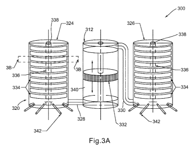
[0054] FIG. 3A illustrates a portion of a compressed air storage system 300
that includes a
compressor/expander device 320 and an actuator 312. The compressor/expander
device 320
illustrates a single stage of a compressed air storage system. The
compressor/expander
device 320 includes a first pressure vessel 324 and a second pressure vessel
326. The first
and second pressure vessels 324, 326 are each coupled fluidly to the actuator
312 by a
conduit or housing 328 and 330, respectively. The actuator 312 can include a
water pump
that includes a hydraulically driven piston 332. The piston 332 is disposed
within a housing
or reservoir 340 and can be driven with one or more hydraulic pumps (not shown
in FIG. 3A)
to move toward and away from the conduit 328 of first pressure vessel 324 to
alternately
reduce and then increase the internal air volume of the first pressure vessel
324 (with an
equivalent, but opposite increase and reduction of air volume in the second
pressure vessel
326). Each of the first and second pressure vessels 324, 326 are at least
partially filled with a
liquid, such as water, that is moved by the actuator 312 to alternately
compress and drive air
from the volume of each of the first and second pressure vessels 324, 326,
when operated in a
14
CA 02762980 2011-11-21
WO 2010/135658 PCT/US2010/035795
compression mode, or to be moved by compressed air received in either of the
first and
second pressure vessels 324, 326 when operated in an expansion mode.
[0055] The compressor/expander device 320 can also include dividers 334 that
can be
positioned within the first and second pressure vessels 324, 326. The dividers
334 can
increase the overall area within a pressure vessel that is in direct or
indirect contact with air,
which can improve heat transfer. The dividers 334 can provide for an increased
heat transfer
area with both air that is being compressed and air that is being expanded
(either through an
air/liquid interface area or air/divider interface), while allowing the
exterior structure and
overall shape and size of a pressure vessel to be optimized for other
considerations, such as
pressure limits and/or shipping size limitations. It is to be appreciated that
the dividers may
heat up or cool down during each compression event, and that the water or
liquid will
thermally recharge the dividers back to the temperature of the water during
each compression
or expansion event, allowing the dividers to act as a rechargeable thermal
capacitor. It is also
to be appreciated that the dividers could have interior spaces that are
occupied with a fluid
such as a refrigerant like water, propane, or other refrigerant, and the
refrigerant could be
cycled outside the compression/ expansion chamber to a heat sink/ source.
[0056] In this embodiment, the dividers 334 are arranged in a stack
configuration within the
first and second pressure vessels 324 and 326. Each divider 334 can be
configured to retain a
pocket of air. In one illustrative embodiment, each of the dividers 334 can
include an upper
wall, a downwardly extending side-wall that may conform in shape and
substantially in size
to the inner wall of the pressure vessel, and an open bottom. Various shapes
of dividers may
be used, as shown, for example, in FIGS. 4A-4C, described in more detail
below. The open
bottom of each of the dividers 334 face in a common, substantially downward
direction when
the pressure vessel is oriented for operation. It is to be appreciated that
although the figures
show dividers that conform in size and shape to the interior of the pressure
vessels 324, 326,
and are generally shaped similarly to one another, other configurations are
also possible and
contemplated, including embodiments that include dividers that are
substantially smaller in
width than the interior of a pressure vessel and/or that are shaped and sized
differently than
one another, among other configurations. Some dividers can be used that do not
face any
particular direction or contain a pocket of air. Such dividers may be
configured to minimize
the distance that heat must travel through the air in order to reach the
dividers, such as a
maximum distance of 1/8 of an inch, and other distances. Such configurations
may include
CA 02762980 2011-11-21
WO 2010/135658 PCT/US2010/035795
parallel dividers, corrugated dividers, intersecting dividers, curved
dividers, dividers made
out of concentric rings, dividers made out of pressed and/or stamped rolled or
sheet metals,
and many other shapes and configurations, some of which are or may be
routinely used in
various thermal transfer devices. Various other shapes and configurations of
dividers can be
used, such as, for example, the dividers that are shown and described in U.S.
Provisional
App. No. 61/290,107, entitled "System and Methods for Optimizing Efficiency of
a
Hydraulically Actuated System," incorporated herein by reference in its
entirety.
[0057] As shown in FIG. 3A, a manifold 336 can extend centrally through the
stack of
dividers 334 and fluidly couple each of the dividers 334 to an inlet/outlet
port 338 of the
pressure vessels 324, 326. In other embodiments, the manifold may include
multiple tubes
and/or may be located peripherally about the stack of dividers or in other
positions. Air may
enter and/or exit the pressure vessels 324, 326 through the ports 338, and can
provide a
conduit for fluid communication between pockets of air associated with each
divider 334. In
other embodiments, such as those in which dividers do not retain a pocket of
air, the manifold
may not be included.
[0058] The embodiment of FIG. 3A is one example of an arrangement of pressure
vessels
and an actuator that can be used within an air compression and storage system.
It should be
understood, that other arrangements are also possible and contemplated. By way
of example,
although the actuator is shown as including a single, double acting piston
that is oriented
vertically, other embodiments may include housings with actuators that include
horizontally
oriented pistons and/or multiple hydraulic pistons that operate in parallel
and/or in series to
move liquid within pressure vessels. According to some embodiments, actuators
may lack
pistons altogether, and instead comprise pumps that move liquid into and out
of the pressure
vessels. Multiple pumps and/or pistons can additionally or alternatively, be
used in parallel
to move liquid into and out of pressure vessels, according to some
embodiments. Still,
according to other embodiments, an actuator, such as a hydraulic piston, may
have a direct
mechanical connection to the motor/alternator of the system, as embodiments of
the system
are not limited to that shown in the figures.
[0059] The dividers 334 in the embodiment of FIG. 3A can increase the area of
heat transfer
surfaces that are in contact with air, including air/liquid interface areas
and air/divider
interface areas, at points during a compression and/or expansion according to
the number of
dividers and/or the surface area of the dividers. The heat transfer from the
air and/or liquid to
16
CA 02762980 2011-11-21
WO 2010/135658 PCT/US2010/035795
the dividers is also affected by the mass of the dividers, their thermal
capacitance, and/or
their thermal conductivity. As is to be appreciated, the air/liquid interface,
absent the
dividers, may be equal to the internal, horizontal cross-sectional area of the
pressure vessel.
Each of the dividers in the embodiment of FIG. 3A provides an air/liquid
interface and/or an
air/divider interface that is substantially equal in size to the cross-
sectional area of the
pressure vessel. In this respect, the total area of the air/liquid and/or the
air/divider interface
may be increased, at any given time during expansion or compression, by a
multiple
substantially equal to the number of dividers and/or the surface area of the
dividers in the
pressure vessel. Additionally, each of the dividers may provide an air/divider
interface that is
also substantially equal in size to the cross-sectional area of the pressure
vessel. In this
regard, pockets of air associated with each divider may be substantially
surrounded with
liquid, either in direct contact with the liquid or in indirect contact with
the liquid through a
surface of the divider, to increase area available for heat transfer with the
liquid and the air.
According to some embodiments, the number of dividers and/or the multiple by
which the
dividers increase the total area of the air/liquid interface and/or
air/divider interface, at a
particular time during compression and/or expansion, may be 5 or higher, 10 or
higher, 20 or
higher, 30 or higher, 40 or higher, or even 50 or higher. In other
embodiments, the dividers
will be more tightly packed, and may be spaced so that in all or a portion of
the pressure
vessel, the dividers are separated from each other by no more than 1 inch, 1/2
inch, '/4 inch, 1/8
inch, 1/16 inch, or some other number.
[0060] The dividers in the embodiment of FIG. 3A may, additionally or
alternatively,
maintain total heat transfer surface areas at high levels substantially
throughout a
compression and/or expansion cycle. The dividers may be placed closer together
toward the
top of the pressure vessel in order to accommodate the increased thermal loads
toward the
end of a compression event and at the beginning of an expansion event. As is
to be
appreciated, the total surface area available for heat transfer during a
compression and/or
expansion process may include the surface area of liquid and the divider that
are in contact
with the air throughout a complete compression and/or expansion cycle. That
is, the total
surface area for heat transfer may include the area that is in direct contact
with the air (either
areas of the liquid or the divider) integrated over the time of a compression
and/or expansion
cycle. In this respect, configuring dividers to maintain an increased heat
transfer surface
throughout a compression and/or expansion cycle may increase the total area
available for
heat transfer, when considered as a time integral over a complete compression
and/or
17
CA 02762980 2011-11-21
WO 2010/135658 PCT/US2010/035795
expansion cycle, by a multiple much greater than the number of dividers that
are present in a
pressure vessel.
[0061] Dividers positioned inside a pressure vessel may additionally or
alternatively reduce
the average minimum distance between points of air that is to be compressed or
expanded
and the thermal conduction surfaces inside of a pressure vessel (either
air/liquid interfaces or
air/divider interfaces) through which heat is to be transferred. The dividers
may also be
textured, pocketed, stamped, coated, serrated, cut, bent, covered with a
coating or layer of
other material, or otherwise treated to increase or decrease their surface
area, increase or
decrease their ability to stay wet or hold water, to increase or decrease
turbulence in the air or
water, all to promote more effective heat transfer while minimizing
irreversible energy losses.
FIG. 3B shows a cross sectional view of a divider 334 that includes an air
pocket 344, and the
surfaces through which heat is to be transferred. As illustrated, the pocket
344 may be a
relatively thin layer of air under or within a divider 334. Any point within
the pocket 344 is
no further away from either the upper wall 346 of the divider 344 (i.e., the
air/divider
interface) or the liquid that is present in the divider 334 (i.e., the
air/liquid interface 348) than
one half of the height H of the divider itself. In this respect, heat, when
transferred in
conduction, will only need to travel, at most, a distance equal to one half of
the height H of
the divider to reach one of the air/liquid interface or the air/divider
interface. Similarly, when
transferred in convective modes, air molecules may only need to travel, at
most, a distance
equal to one half of the height H of the divider to reach one of the
air/liquid interface or the
air/divider interface for heat transfer to occur.
[0062] Minimizing the distance between air in the pressure vessel and surfaces
through or
into which heat is to be transferred may substantially improve heat transfer
to and/or from air
that is compressed and/or expanded.
[0063] Air typically has the lowest thermal conductivity among the media
through which
heat is transferred in the compression/expansion device. By way of example,
air has a
thermal conductivity of about 0.024 Watts/meter-Kelvin while water has a
thermal
conductivity that is an order of magnitude greater that that of air (0.58
Watts/meter-Kelvin)
and steel has thermal conductivity that is about three orders of magnitude
greater than that of
air (43 Watts/meter-Kelvin for 1% carbon steel). Reducing the distance that
heat travels
through air essentially reduces the greatest bottleneck to heat transfer by
reducing the
distance of the most thermally resistive element along the heat transfer path.
18
CA 02762980 2011-11-21
WO 2010/135658 PCT/US2010/035795
[0064] Dividers may be shaped differently than shown in the embodiment of FIG.
3A and/or
may be packaged within pressure vessels in different arrangements. The
dividers of FIGS.
3A and 3B are downwardly facing (and shaped substantially like inverted
dishes), so as to
form and trap air pockets therein.
[0065] It is to be appreciated that other shapes are possible, such as
dividers with domed
upper walls, as shown in FIG. 4A, flared sidewalls as shown in FIG. 4B (either
flared
inwardly or outwardly), or other shapes, as embodiments are not limited to
that which is
shown in the figures. Additionally or alternatively, although the dividers of
FIG. 3A and 3B
are sized to occupy an area substantially equal to a cross-sectional area of
the pressure vessel,
smaller dividers are also possible.
[0066] In the illustrated embodiments of FIGS. 4A and 4B, a divider 434 is
disposed within a
pressure vessel 426. The divider 434 includes a domed upper wall 446 and one
or more
passages 450 may be provided between each of the pockets created by the
dividers 434 and a
manifold 436 to allow the passage of air and/or liquid therebetween. It is
also contemplated
that fluid communication between the dividers 434 and manifold 436 may be
provided by
different means, such as by manifolds that are positioned external to a
pressure vessel and/or
manifolds that are positioned off-center within a pressure vessel.
[0067] FIG. 4B illustrates an embodiment that includes a divider 534 is
disposed within a
pressure vessel 526. The divider 534 includes an upper wall 546 and one or
more passages
550 may be provided between each of the pockets created by the dividers 534
and a manifold
536 to allow the passage of air and/or liquid therebetween. The divider 534
also includes
outwardly flared side-walls 552.
[0068] Dividers may be configured to create a turbulent air/liquid interface
to further increase
the heat exchange between the air and liquid of a divider of between air and
surfaces of the
divider itself. By way of example, according to some embodiments turbulators
may be
positioned on the interior of a divider to agitate liquid as the air/liquid
interface moves
upward or downward during compression and/or expansion modes, effectively
increasing the
air/liquid interface area and promoting convective heat transfer to and/or
from air. According
to other embodiments, such as shown in FIG. 4C, a divider 634 is shown
disposed within a
pressure vessel 626 and includes a bank of heat transfer fins 654 that may be
incorporated
onto surfaces of the divider 634 to promote heat transfer between an air
pocket of a divider
19
CA 02762980 2011-11-21
WO 2010/135658 PCT/US2010/035795
and the surfaces (e.g., upper wall 646) of the divider. It is to be
appreciated, however, that
not all embodiments include turbulators or banks of fins, as the various
embodiments are not
limited to that shown or explicitly described herein.
[0069] As mentioned above, the size and shape of a pressure vessel may be
optimized for
considerations other than the air/liquid interface area when a plurality of
dividers are used to
define the air/liquid interface. By way of example, according to some
embodiments, dividers
may allow the total area of the air/liquid interface to be maximized while the
overall size of
the pressure vessel is designed to have a maximum outside dimension (i.e., the
greatest of the
length, width, and height of a pressure vessel) below a particular distance,
which may prove
useful when pressure vessels are to be packaged for shipment either separately
or in an ISO
standard shipping container. Additionally or alternatively, pressure vessels
may be shaped to
provide for optimal structural integrity, having cylindrical,
spherical/cylindrical, or other
shapes. According to some embodiments, the maximum dimension of a cylindrical
pressure
vessel with a rounded top and bottom structure may be about 6 meters while
having a total
air/liquid surface area of about 140 square meters, a maximum dimension of
about 2.5 square
meters and a total air/liquid surface area of about 40 square meters, or a
maximum dimension
of about 2 meters and a total air/liquid surface area of about 10 square
meters.
[0070] As discussed above, heat can be transferred from and/or to air that is
compressed
and/or expanded by liquid (e.g., water) within a pressure vessel. An
air/liquid or air/divider
interface (e.g., provided in part by dividers discussed above) may move and/or
change shape
during a compression and/or expansion process in a pressure vessel. This
movement and/or
shape change may provide a compressor/expander device with a heat transfer
surface that can
accommodate the changing shape of the internal areas of a pressure vessel
through which
heat is transferred during compression and/or expansion. In some embodiments,
the liquid
may allow the volume of air remaining in a pressure vessel after compression
to be nearly
eliminated or completely eliminated (i.e., zero clearance volume).
[0071] FIGS. 5A-5C show the air/liquid interface associated with a divider 734
at various
stages of compression and expansion. At the beginning of a compression cycle,
an air pocket
is present inside of the divider 734 with the air/liquid interface 748 just
above the lower edge
of the divider side wall 752, as shown in FIG. 5A. As additional liquid is
introduced into the
volume of the pressure vessel, the air/liquid interface 748 moves upward as
the additional
liquid drives the air/liquid interface 748 toward the divider upper wall 746
and compresses air
CA 02762980 2011-11-21
WO 2010/135658 PCT/US2010/035795
within the volume of the pressure vessel 726. The process continues until the
air/liquid
interface 748 eventually reaches the passages 750 between the divider 734 and
manifold 736,
and liquid begins to enter the manifold 736 itself, as shown in FIG. 5B.
Eventually, near the
end of the compression cycle, the air/liquid interface 748 may contact the
upper wall 746 of
the divider 734, as shown in FIG. 5C, and nearly or completely fill the
manifold 736.
[0072] According to some embodiments, the area of the air/liquid interface of
a divider may
remain substantially constant, at least until the air/liquid interface reaches
the top of the upper
wall, due to a substantially constant cross-sectional area between sidewalls
of a divider,
although there may be some insubstantial change in air/liquid interface area
due to flaring
and/or a reduction in area of air-exposed side wall as the air/liquid
interface moves higher
within a pocket of air. A relatively constant, relatively high air/liquid
interface area
throughout the compression process may help promote heat transfer from the air
throughout
the compression process.
[0073] According to some embodiments, features may be included in a
compressor/expander
device to balance the flow of air and/or liquid between a manifold and pockets
of air under
the dividers of a pressure vessel. The flow may be balanced such that the
air/liquid interface
of each of the dividers of a pressure vessel, or some portion of the dividers
of a pressure
vessel, may move within dividers synchronously, such as to reach upper walls
of the dividers
at a common time. In this respect, areas for heat transfer between air at the
air/liquid
interface and at the air/divider interface may be maintained in each of the
dividers throughout
a compression and/or expansion process. In some embodiments, ports between the
manifold
and each of the dividers may be sized differently to accomplish balanced flow.
Additionally
and/or alternatively, ports between the manifold and dividers may include
valves to provide
balanced flow. The ports and/or valves may be configured to account for the
gravitationally
induced pressure gradient in the pressure vessel. For example, the ports near
the bottom of
the pressure vessel may be sized smaller than the ports near the top of the
pressure vessel in
order to accommodate the higher pressures expected at the bottom of the
pressure vessel.
[0074] During an expansion mode, the air/liquid interface moves in the
dividers of a pressure
vessel essentially in the opposite direction as during compression. For
instance, the
expansion process may begin with the pressure vessel, including the manifold
and dividers,
entirely or substantially filled with liquid. Air forced into the port of the
pressure vessel may
move liquid downwardly through the manifold, as shown in FIG. 5C, eventually
passing
21
CA 02762980 2011-11-21
WO 2010/135658 PCT/US2010/035795
through the passages and entering each of the dividers, creating pockets of
air and air/liquid
interfaces therein. As air continues to expand into the volume, the air/liquid
interface of each
divider may move lower, as shown in FIG. 5B, eventually reaching a level just
above the
lower edge of the dividers, as shown in FIG. 5A. Any air/liquid interface that
happens to
pass below the lower end of a divider side wall may cause air to pass between
the inner
pressure vessel walls and the outer walls of the dividers. This air may
eventually reach the
top of the pressure vessel and re-enter the manifold through passages near the
top of the
pressure vessel or through another mechanism included for this purpose. In
another
embodiment, air forced into the port of the pressure vessel may move liquid
downwardly past
the dividers, without creating pockets of air. In this configuration, the
pressure vessel holds
only one pocket of air, and the air volume grows larger during the expansion
process until the
expansion stroke is concluded.
[0075] Similar to compression, the overall air/liquid interface area may
remain substantially
constant throughout the expansion process, at least after moving away from the
upper surface
of each divider and before the air/liquid interface moves below the lower edge
of any divider.
In other configurations, the air/divider interface will increase linearly or
geometrically
through the expansion process.
[0076] Using liquid in a pressure vessel to compress and displace air may
provide several
benefits. According to some embodiments, the liquid may act as a water piston
that conforms
to the shape of a pressure vessel when used to compress and displace air
therefrom.
According to some embodiments, the water piston may essentially occupy the
entire volume
of the pressure vessel, thus eliminating any clearance volume. Using water as
the positive
displacement mechanism also provides a heat management mechanism, thus serving
multiple
purposes. Additionally and/or alternatively, in some embodiments, excess
liquid may be
introduced to the pressure vessel as liquid condenses out of air that is
compressed.
Condensed liquid may be combined with liquid that resides in the pressure
vessel without
adverse effects. It is possible, according to some embodiments, that enough
liquid may
condense to cause the total volume of liquid to exceed the volume available in
a pressure
vessel at some points during the operating cycle of a compressor/expander
device. In such
scenarios, excess liquid may exit the pressure vessel through the port or
through another
mechanism included for this purpose, without adverse effect, along with air
that is being
compressed and displaced. Excess liquid may be removed through moisture traps,
or by
22
CA 02762980 2011-11-21
WO 2010/135658 PCT/US2010/035795
means known to those of skill in the art. Any liquid deposited into the
pressure vessel during
compression is removed and retained at minimal loss, using an intermediate
reservoir, to a
holding tank. During expansion, liquid can be vaporized, thereby removing
liquid from the
pressure vessel. Liquid held in the holding tank can be re-injected during
expansion so as to
maintain the total liquid volume in the system constant. In this manner the
compression/expansion system does not consume any liquid.
[0077] Using water as the positive displacement mechanism also provides a near
zero friction
piston seal, and a zero leakage piston seal, which reduces energy losses due
to friction,
reduces maintenance and inefficiency due to seal wear, eliminates the need to
replace the
piston seal, improving device and process reliability. It also eliminates the
need to lubricate
the piston on the cylinder or to maintain, service, and replace the lubricant
or its filter and/or
filtering system, or to cool the lubricant, and to avoid the energy losses
associated with
pumping, filtering, and cooling the lubricant.
[0078] Liquid within a pressure vessel, according to some embodiments, may
also act in
combination with a heat exchanger to transfer heat from air that is compressed
(or to air that
is expanded) to an external environment (or from an external environment). By
way of
example, FIG. 6 shows a heat exchanger 854 that extends through a wall of the
pressure
vessel 826 to contact both the liquid and the external environment. As
illustrated, the heat
exchanger may include a circular array of heat pipes, although other types of
heat exchangers
may be used, additionally or alternatively. As is to be appreciated, heat
pipes operate with a
refrigerant that evaporates at one end of the pipe where heat is received, and
that condenses at
the other end of the pipe where heat is removed, approximately at the same
temperature as
that which heat is received, or within a small range of temperatures, such as
ranges of about
40 C. It is to be appreciated that FIG. 6 shows but one heat pipe arrangement
that may be
used to transfer heat to or from liquid of a pressure vessel, and that other
arrangements may
also exist, such as arrangements that include heat pipes or other types of
heat exchanges
positioned in actuator housings or other components that are in fluid
communication with a
pressure vessel. According to another embodiment, heat pipes may be provided
in direct
contact with the dividers, some of which may trap air pockets within a
pressure vessel. It is
also to be appreciated that any heat source or heat sink may be used in the
environment
external to the pressure vessel to provide or receive heat therefrom, as
embodiments of the
system are not limited to any one arrangement of heat sources or heat sinks.
23
CA 02762980 2011-11-21
WO 2010/135658 PCT/US2010/035795
[0079] The use of a liquid as a medium through which heat passes during
compression and/or
expansion may allow for a continuous cooling process. That is, during
compression the
liquid may receive heat from air that is being compressed, and pass this heat
to the external
environment continuously, both while air is being compressed and while air is
being received
by the pressure vessel for later compression. Similarly, heat addition may
occur when a
compressor/expander device is operating in an expansion mode both during
expansion and as
expanded air is passed from a pressure vessel.
[0080] According to some embodiments, the liquid in the compressor/expander
device may
include water, although other liquids may be used, additionally or
alternatively. As is to be
appreciated, water may naturally condense out of air that is being compressed
by the system,
and in this respect, may combine with the liquid without adverse impact.
Additionally, when
used in embodiments of the expander/compressor device, water may evaporate
into air during
expansion without having an adverse impact. Other types of liquids, however,
may be used
in addition to or in place of water. Some examples of such liquids may include
additives or
entire liquids formulated to prevent freezing, such as glycol, liquids that
prevent evaporation,
such as glycerin, liquids to prevent corrosion, liquids to control viscosity,
liquids to control
thermal conductivity, liquids to control lubricity, liquids to prevent
biological agents from
growing, liquids to adhere to surfaces of the pressure vessel, liquids to
enhance the operation
of the valves in the system, liquids to handle the build-up of any minerals
such as salt from a
salt cavern, and/or liquids to prevent foaming.
[0081] One embodiment may use a phase change material as the
compression/expansion
medium directly in the pressure chamber. In this way, the liquid not only
provides the surface
with which air is compressed, but also serves as a heat transfer mechanism. A
liquid
undergoing a phase change (whether to or from gas or solid phases) remains at
constant
temperature. This can be taken advantage of within the pressure vessel to keep
the expansion
or compression temperature isothermal by direct means, without requiring a
heat exchange
device. Heat transfer occurs by direct contact between the air and phase
change liquid. This
heat transfer mechanism can be implemented in a variety of techniques apparent
to the
artisan, including contacting the air with a spray or mist of the working
liquid (such as water),
using a working liquid that boils at a suitable temperature and the vapor
phase of which can
be readily separated from the air after compression and before storage (e.g.
by condensation),
and/or using working liquid that freezes at a suitable temperature (e.g. by
operating the
24
CA 02762980 2011-11-21
WO 2010/135658 PCT/US2010/035795
system at conditions in which the working liquid is a mixture of the liquid
and its solid form,
such as a water ice slush).
[0082] Compressor/expander devices may be arranged in series to create a multi-
stage
compressor/expander device, according to some illustrative embodiments. FIGS.
7A-71
illustrate an example of a multi-stage compressor/expander device including
three-stages.
Each of the first, second, and third stages comprise a pair of pressure
vessels, similar to the
pressure vessels described with respect to FIG. 3A, connected in fluid
communication to an
actuator. In other configurations, there could be one, three, four, or more
pressure vessels in
each stage. Specifically, an actuator for the first stage includes a housing
or conduit 940
disposed between a first pressure vessel 926 and a second pressure vessel 928,
an actuator for
the second stage includes a housing 940' disposed between a first pressure
vessel 926' and a
second pressure vessel 928', and an actuator 940" for the third stage includes
a housing 940"
disposed between a first pressure vessel 926" and a second pressure vessel
928". A piston
932, 932', 932" is movably disposed within the housing 940, housing 940' and
housing
940", respectively. Multiple dividers 934 are disposed within each of the
first pressure
vessel 926 and the second pressure vessel 928 of the first stage, multiple
dividers 934' are
disposed within each of the first pressure vessel 926' and the second pressure
vessel 928' of
the second stage, and multiple dividers 934" are disposed within each of the
first pressure
vessel 926" and the second pressure vessel 928" of the third stage, as shown,
for example, in
FIGS. 7B-7I.
[0083] The first and second pressure vessels 926 and 928, respectively, of the
first stage each
include a first valve 956 that opens to allow the receipt of air from the
environment. These
valves, and those referenced below, may be actively controlled, passively
controlled, or may
be an active or passive port. Each of the first and second pressure vessels
926, 928 of the
first stage is also fluidly coupled to a pressure vessel (926', 928') of the
second stage by a
conduit 958, 960 that may include one or more second valves 962 to selectively
open and
close fluid communication between the volumes of the corresponding pressure
vessels. The
pressure vessels 926', 928' of the second stage are also fluidly coupled to
pressure vessels
926", 928" of the third stage through conduits 964, 966, and include one or
more third
valves 968, 968' that selectively open and close fluid communication
therebetween. Fourth
valves 970 are additionally placed downstream to the ports of pressure vessels
926", 928" at
the third stage to control the passage of air between the third stage and a
storage structure
CA 02762980 2011-11-21
WO 2010/135658 PCT/US2010/035795
(not shown) to or from which pressurized air is passed. It is to be
appreciated that, although
described herein as a three-stage compressor/expander device, fewer or
additional pressure
vessels and/or valves can be included to create fewer or additional stages of
compression/expansion.
[0084] According to one illustrative embodiment, constructed similarly to that
shown in FIG.
7A, the first stage may be configured to provide a compression ratio of about
10.14:1, the
second stage has a compression ratio of about 5.5:1, and the third stage of
has a compression
ratio of about 3.3:1. Such compression ratios may be suitable for a system
that is configured
to compress air to a pressure of about 184 atmospheres from a starting
pressure of about
atmospheric pressure, and to expand air from 184 atmospheres to about
atmospheric pressure.
A compressor/expander device configured in this manner may have a power rating
of about 2
megawatts, according to one embodiment. In another embodiment, the stages may
have
roughly equivalent pressure ratios of around 5, 6, 7, or some other number. In
another
embodiment, a separate compression and/or expansion device or process such as
a screw
compressor and/or expander, centrifugal compressor and/or expander, bellows
compressor
and/or expander, piston compressor and/or expander, or other compressor and/or
expander
device or process may provide compression and/ or expansion for the first
stage, the second
stage, the third stage, or some combination of stages, at a pressure ratio of
2:1, 3:1, 4:1, 5:1,
6:1, or some other number.
[0085] In the embodiment of FIG. 7A, a compression cycle may begin with the
piston 932 of
the actuator for the first stage moving away from the first pressure vessel
926 of the first
stage to increase the volume available for air inside of the first pressure
vessel 926 of the first
stage, as represented by FIG. 7B. This movement may pull water out of the
dividers 934 of
the first pressure vessel 926, creating negative pressure that draws ambient
air into the first
pressure vessel 926 into pockets within each of the dividers 934, creating
additional air/liquid
and air/divider interfaces through which heat may be transferred. In another
embodiment,
this movement may pull water out of the dividers 934 of the first pressure
vessel 926,
creating negative pressure that draws ambient air into the first pressure
vessel 926 into and
through or past the dividers 934, creating additional air/liquid and
air/divider interfaces
through which heat may be transferred. When the piston 932 reaches the end of
this stroke,
the first valve 956 between the atmosphere and the first pressure vessel 926
is closed and the
second valve 962 between the first stage and second stage is opened, as shown
in FIG. 7C.
26
CA 02762980 2011-11-21
WO 2010/135658 PCT/US2010/035795
The compression stroke begins as the piston 932 returns toward the first
pressure vessel 926,
decreasing the volume available for air in the combined volume of the first
pressure vessel
926 of the first stage and the first pressure vessel 926' of the second stage,
compressing and
displacing the air toward the first pressure vessel 926' of the second stage,
as shown in FIG.
7D. In this respect, compression of air may take place across pressure vessels
of different
stages. As the piston 932 of the first stage nears the end of its stroke
toward the first pressure
vessel 926, the piston 932' of the second stage nears the end of its stroke
away from the first
pressure vessel 926' of the second stage and the second valve 956 between the
first pressure
vessel 926 of the first stage and the first pressure vessel 926' of the second
stage closes, as
shown in FIG. 7E. Operation between the second and third stages of the
compressor/expander device mirrors the above described operation between the
first and
second stages. Operation between the third stage and the storage structure,
however, may
differ in that the valve (e.g., valve 970) to the storage structure may open
when the pressure
at the third stage exceeds the pressure of air in the storage structure,
rather than when the
piston of the third stage begins its compression stroke.
[0086] The above described compression cycle differs from existing positive
displacement
compression cycles, in that the compression in the pressure vessels includes
the air volume of
pressure vessels of multiple stages, rather than that of a single stage. In
contrast, prior art
compressors typically compress air in a single compression chamber (i.e.,
pressure vessel). It
is to be appreciated other embodiments could be implemented with any number of
pressure
vessels at a common stage, or spread among multiple stages, as the various
embodiments are
not limited to that described herein. Additionally, in embodiments where
compression occurs
across pressure vessels of different stages, volumetric ratios of any stage
may be modified by
adjusting valve timing between various stages.
[0087] An expansion cycle, in an embodiment constructed like that of FIG. 7A,
is
represented in FIGS. 7F-7I. Expansion begins with air expanding into a first
pressure vessel
926" of the third stage from a storage structure (not shown), as represented
in FIG. 7F. This
expanding air moves liquid to drive the third actuator (e.g. piston 932") away
from the first
pressure vessel 926" of the third stage. This process continues, with the
third valve 968' to
the first pressure vessel 926' of the second stage closed, as shown in FIG.
7G. As the third
piston 932" nears the end of travel away from the first pressure vessel 926"
of the third
stage, as shown in FIG. 7H, the fourth valve 970 closes fluid communication
with the cavern
27
CA 02762980 2011-11-21
WO 2010/135658 PCT/US2010/035795
(e.g., storage structure). The third valve 968' is then opened to allow the
air to expand into
the first pressure vessel 926' of the second stage, driving the second
actuator (e.g., piston
932'), as shown in FIG. 71. Operation between the third and second stages, and
then the
second and first stage of the compressor/expander device mirrors the above-
described
operation between the storage structure and the third stage.
[0088] Compressor/expander devices may be installed modularly, allowing
systems to be
constructed for a wide range of energy storage needs. By way of example, a
compressor/expander device, such as the device of FIG. 7A, may be sized to
store and
generate between 1.0 and 5.0 megawatts of power, although it is to be
appreciated, that other
embodiments may include higher or lower power ratings. A plurality of
compressor/expander devices may be installed together and operated in parallel
for
installations having higher energy storage power requirements, for instance as
high as 300
megawatts or higher, according to some embodiments. Installations that include
multiple
compressor/expander devices, arranged in parallel, may operate at less than
full capacity by
shutting down a portion of the compressor/expander devices, or by operating
some or all of
the compression/ expansion devices at less than their full power capacity,
which may promote
efficient system operation. Installations that include multiple
compressor/expander devices,
arranged in parallel, may operate at more than full rated capacity for some
duration in order
to meet a particular operating requirement, such as compressing air when power
prices are
low or negative, or expanding air when power prices are high. Such operations
may be
affected by increasing the speed of the compression stroke, increasing the
mass of air in the
intake of the third stage from the storage vessel by controlling the timing of
the valves in the
system, particularly the valve(s) between the storage vessel and the third
stage. Additionally
or alternatively, installations that include multiple compressor/expander
devices may be
constructed modularly to allow system operation before all
compressor/expanders are
installed, or during periods of time when one or more compressor/expanders are
down for
maintenance, repair, replacement, or for other reasons. Additionally or
alternatively,
installations that include multiple compressor/expander devices may be
constructed
modularly to allow more compressors/ expanders (the spares) to be constructed
than called
for by the power rating of the project, allowing the spares to take over just
as or shortly after
various compressor/ expander units are turned off for maintenance, repair,
replacement, or
other reasons, thereby maintaining a higher power rating for the power plant.
28
CA 02762980 2011-11-21
WO 2010/135658 PCT/US2010/035795
[0089] Embodiments of the compressor/expander device can accommodate a wide
range of
operating power levels. As is to be appreciated, it may be desirable to store
or release energy
at varying rates, particularly when energy to be stored is received from a
less predictable
source, such as a wind farm. A compressor/expander device described herein can
act as a
positive displacement device, meaning that the overall device intakes a common
volume of
air during each cycle, although each stage compresses this initial volume to
different values.
Such positive displacement devices may operate at different power levels by
compressing (or
expanding) different masses of air that have a common volume, unlike
centrifugal
compressors typically used in CAES systems that operate efficiently primarily
at a relative
narrow range of power levels. Additionally or alternatively, installations
having a plurality of
compressor/expander devices that operate in parallel may activate only a
portion of the
installed compressor/expander devices to accommodate different operating power
levels.
[0090] The compressor/expander devices may operate at relatively slow speeds,
which may
provide for improved heat transfer, improved energy consumption and/or
generation,
improved durability, decreased entropy losses, decreased pressure drops
through valves,
pipes, and ports, decreased thermal cycling of the compressor/ expander,
and/or improved
reliability. According to some embodiments, a compression or expansion cycle
of the
compressor/expander device may allow for improved heat transfer, which may
allow the
device to achieve near isothermal behavior during expansion and/or
compression.
Additionally, lower temperatures associated with improved heat transfer and
less friction at
joints and sliding contacts in the expander/compressor device may provide for
improved
durability and reliability, as compared to higher speed machinery.
[0091] Slower operating speeds and/or increased heat transfer capacities of
various
embodiments of the compressor/expander device enable heat transfer to occur
with the
external environment across relatively low temperature differences. According
to some
embodiments, the expander/compressor device may operate with near isothermal
compression/expansion processes while exchanging heat with the external
environment
across temperature differences as low as 50 C, as low as 25 C, or even as
low as 5 C.
[0092] According to some embodiments, low-grade heat sources and/or heat sinks
may be
used to provide heat to and receive heat from the compressor/expander during
expansion/compression modes. In this respect, the system may be capable of
operating
without burning fossil fuels, such as for heating air at expansion. It is to
be appreciated,
29
CA 02762980 2011-11-21
WO 2010/135658 PCT/US2010/035795
however, that embodiments of the system may also be operated in conjunction
with power
plants or other systems that do burn fossil fuels. Some embodiments may use
geothermal
energy, solar energy, and other energy inputs, water, salt water, gravel,
water and gravel, salt
water and gravel, and other thermal heat sinks and sources as heat sources
and/or sinks,
taking advantage of the substantially constant ground temperatures that exist
4 to 10 meters
below the earth's surface and substantially constant temperatures associated
with
subterranean caverns, when used as storage structures. Additionally, according
to some
embodiments, compression may occur at night when the air temperature is lower
and may
provide an environment to which heat is removed while expansion occurs during
the day
when temperatures are higher and may provide a source of heat used in the
expansion
process.
[0093] According to some embodiments, a system that utilizes a
compressor/expander device
may have a modular construction. By way of example, FIG. 8 shows one
embodiment of a
compressor/expander device 1020 that is incorporated directly into the
structure of a wind
turbine 1014. The wind turbine 1004 includes a rotor 1072 that is connected to
and drives a
low speed hydraulic pump 1074 through a gearbox 1076. The gearbox 1076 may be
a
mechanical gearbox, a hydraulic gearbox, or may include other types of
gearboxes. A
conduit 1078 connects a hydraulic fluid output of the hydraulic pump 1074 to a
hydraulic
motor 1080 that is mechanically connected to a generator 1082. The conduit
1078 also
connects the hydraulic fluid output of the hydraulic pump 1074 to one or more
actuators of a
compressor/expander device 1020, that may be positioned in the tower 1016 of
the wind
turbine 1014. Each of the gear box 1076, hydraulic pump 1074, hydraulic motor
1080, and
generator 1082 are shown positioned in the nacelle 1018 of the wind turbine
1014, but could
be positioned elsewhere in other embodiments. One or more valves 1084 may
control the
flow of hydraulic fluid from the hydraulic pump 1074 to the hydraulic motor
1080 and/or
compressor/expander device 1020, according to a mode in which the system is
operating.
The wind turbine 1014 also includes a storage structure 1086 that may be
located in portions
of the tower of the wind turbine 1014 and/or a storage structure 1022 in a
foundation 1088
that supports the wind turbine 1014. In this respect, the wind turbine may
provide for a self-
contained energy storage and retrieval system that may prove beneficial for
offshore
applications.
CA 02762980 2011-11-21
WO 2010/135658 PCT/US2010/035795
[0094] The system of FIG. 8 may operate in different modes. In a first mode of
operation,
wind energy may be directed solely to the generator 1082 of the wind turbine
1014. In this
mode, one or more valves 1084 may be positioned so that hydraulic power does
not go to the
compressor/expander device 1020, such that any power associated with wind
driving the
rotor 1072 is converted through the gear box 1076, the hydraulic pump 1074,
the hydraulic
motor 1080, and the generator 1082 into electricity. In a second mode of
operation, wind
energy may be used exclusively to drive the compressor/expander device 1020 to
store
energy as compressed air. In this mode, the one or more valves 1084 may be
positioned such
that hydraulic power is directed solely to the compressor/expander device 1020
from the
hydraulic pump 1074. The valves 1084 may also be positioned such that
hydraulic fluid from
the hydraulic pump 1074 goes to the compressor/expander device 1020 and the
combination
of the hydraulic motor 1080 and generator 1082, such that wind energy may be
used to
compress air and to create electricity at a common time. When it is desirable
to release
energy that is stored in the system, compressed air may be released for
expansion through the
compressor/expander device 1020 in yet another mode of operation. Pressurized
hydraulic
fluid, output from the compressor/expander device 1020, may drive the
generator 1082,
through the hydraulic motor 1080, to create electric energy. This may occur
either to assist
the hydraulic pump 1074 that is being driven by the rotor 1072 when there is
adequate wind,
or as a sole source of pressurized hydraulic fluid, when there is inadequate
wind to rotate the
rotor 1072.
[0095] According to some embodiments, a system that is incorporated into the
structure of a
wind turbine may share components with the wind turbine itself, realizing
additional and/or
alternative efficiencies. By way of example, a compressor/expander device may
utilize
control software normally dedicated to the wind turbine or otherwise share
control software
and/or hardware with the wind turbine. The generator, gearbox, hydraulic pump,
valves,
and/or hydraulic motor may be common to both the compressor/expander device
and the
wind turbine to reduce the cost and number of components used in a system.
[0096] FIG. 9 shows a cross-sectional, schematic view of one embodiment of a
compressor/expander device 1120 that may prove suitable for packaging within
the tower of
a wind turbine. As shown, first and second pressure vessels 1126 and 1128 are
positioned
vertically with respect to one another. The first pressure vessel 1126
includes dividers 1134
and a manifold 1136, and the second pressure vessel 1128 includes dividers
1134' and a
31
CA 02762980 2011-11-21
WO 2010/135658 PCT/US2010/035795
manifold 1136'. The first and second pressure vessels 1126, 1128 are connected
by a
hydraulic actuator 112 and a housing 1140 that is wider in diameter than each
of the pressure
vessels 1126, 1128. A hydraulically actuated piston 1132 is disposed within
the housing
1140. The larger width of the housing 1140, relative to the pressure vessels
1126, 1128, may
reduce distances and, correspondingly, velocities travelled by liquid at a
given operating
speed. Reduced liquid velocities may, in turn, reduce liquid pumping
resistance within the
compressor/expander device 1120 to help improve the compressor/expander device
1120
operating efficiencies.
[0097] A compressor/expander device, according to some embodiments, may
operate at a
substantially constant output power when in an expansion mode for varying
storage structure
air pressure levels. FIG. 10 is a graph showing air pressures through each of
three stages of a
compressor/expander device for two storage structure pressure levels,
according to one
embodiment. As illustrated, air pressures throughout the expander devices may
follow a
similar but shifted curve after initial expansion to produce a similar amount
of power for
storage structure air pressures between 100 and 180 bar, represented by the
dotted line in Fig.
10. It is understood that other pressure ranges, however, may alternatively be
employed.
Sensors, valves, controllers and other devices may be used to control a mass
of air that enters
the compressor/expander device from the storage structure to accomplish this.
In one
embodiment the final discharge pressure may be higher than ambient air
pressure.
[0098] In another embodiment, the vessels and pumps are sized to admit a
greater and
adjustable volume of air during expansion than compression enabling them to
generate the
full rated power during expansion from the lowest storage pressure. A
vessel/pump system
designed according to this embodiment will only be fully utilized during
expansion from the
lowest design storage pressure. Further, a vessel/pump system designed
according to this
embodiment will always be fractionally used during compression. In another
embodiment
the final discharge pressure may approach ambient air pressure.
[0099] In another embodiment, regenerative heat exchange techniques can be
used to extract
heat energy from the air during compression (e.g. via the working liquid
and/or the dividers)
and to insert heat energy into the air during expansion (again, e.g. via the
working liquid
and/or the dividers). This functionality can be implemented using any of a
variety of
techniques that will be apparent to the artisan. For example, a regenerative
heat exchange
system can include a heat exchanger in thermal communication with the
32
CA 02762980 2011-11-21
WO 2010/135658 PCT/US2010/035795
compressor/expander device (e.g. that circulates a suitable thermal working
fluid through a
heat exchanger, the other side of which is exposed directly to the air or
working fluid in the
compressor/expander device, or indirectly via the dividers or other
intermediary heat transfer
structure) and a heat energy storage reservoir (e.g. a an insulated storage
tank for the thermal
working fluid). During compression, the regenerative heat exchange system can
be operated
to circulate the thermal working fluid to extract heat energy from the air and
to insert that
heat energy into the storage reservoir. Conversely, during expansion, the
regenerative heat
exchange system can be operated to circulate the thermal working fluid to
extract heat energy
from the reservoir and to insert that heat energy into the air.
[00100] Heat removal from air that is being compressed and/or heat addition to
air that
is being expanded may help minimize temperature changes that occur in the air
during these
processes and, as described herein, may help a system achieve process
conditions that are
isothermal, or acceptably close to isothermal to be economically optimal. For
example, as
used herein, "isothermal" or "near isothermal" can means that the heat
transfer process is
characterized by a polytropic index of about 1.1 or less, and preferably about
1.05 or less.
According to one embodiment, air experiences less than a change in temperature
of about
1.6 C or less throughout compression and/or expansion processes in a
compressor/expander
device (corresponding to a polytropic constant of 1.023). It is to be
understood, however,
that the system may also be operated in configurations that implement
compression/expansion processes corresponding to a polytropic index greater
than 1.1. For
example, the equipment and/or operating costs required to operate a system so
as to achieve a
polytropic index of 1.05 may exceed the costs of the thermal inefficiencies in
implementing
an operating a system that achieves a polytropic index of greater than 1.1. It
may therefore
be desirable to implement the system so as to operate at the higher polytropic
index.
[00101] Embodiments of the compressor expander device may be configured to
reach
operating speeds and/or power levels quickly to provide ancillary services to
power facilities,
including but not limited to, black start services, spinning reserve services,
voltage support
services, and/or frequency regulation services.
[00102] It is to be appreciated that, although described herein primarily for
use with
wind turbines and/or wind farms, embodiments of the compressor/expander device
may be
used with various types of power production facilities, including but not
limited to solar
power plants, coal fired power plants, gas fired power plants, nuclear power
plants,
33
CA 02762980 2011-11-21
WO 2010/135658 PCT/US2010/035795
geothermal power plants, biomass power plants, and/or hydro power plants, to
name a few.
In one embodiment, the thermal energy from a solar plant would be used through
the device
and process described herein rather than or in addition to a more traditional
steam turbine or
organic Rankine Cycle turbine, or other heat engine, as part or all of the
heat source to
improve the efficiency of generating power when expanding compressed air. The
conversion
efficiency of thermal energy to electric power from the solar plant may be
70%, 80%, and
higher through this system.
[00103] Although the embodiments of a compressor/expander device are described
herein for use in compressing or expanding air, it is to be appreciated that a
compressor/expander device may be used to compress and/or expand any other
gaseous
substance, such as, but not limited to carbon dioxide, natural gas, oxygen,
nitrogen, butane,
propane, and other gasses. It is also to be appreciated that embodiments of
the
compressor/expander device are described herein for use with water or liquid,
and that any
other liquid-like substances that may also be used as a heat transfer and/or
pressure transfer
medium, including other types of coolants.
[00104] Having thus described several aspects of at least one embodiment of
this
invention, it is to be appreciated various alterations, modifications, and
improvements will
readily occur to those skilled in the art. Such alterations, modifications,
and improvements
are intended to be part of this disclosure, and are intended to be within the
scope of the
invention. Accordingly, the foregoing description and drawings are by way of
example only.
[00105] In some embodiments, a device as described herein includes at least
one
pressure vessel in which air may be compressed and/or expanded. The at least
one pressure
vessel is at least partially filed with liquid and, at times, with air. The at
least one pressure
vessel is coupled to an actuator that moves the liquid in the volume to
compress air in the
pressure vessel or that is moved by air that is expanded within the pressure
vessel to drive the
actuator. The pressure vessel includes a plurality of dividers that hold air
and/or are located
throughout the pressure vessel so as to create a high area for thermal
conduction to/from the
air, the dividers, and the liquid. The dividers may substantially reduce the
aggregate length
of the heat path between air and liquid or structure, as compared to similarly
constructed
vessels that lack dividers. The dividers may substantially increase the total
area of the
air/liquid interface, as compared to similarly constructed vessels that lack
dividers.
Additionally, the dividers may provide an air/liquid interface and/or
air/divider interface
34
CA 02762980 2011-11-21
WO 2010/135658 PCT/US2010/035795
and/or liquid/divider interface that remains substantially constant in area
throughout and
toward the end of a compression or expansion cycle, where air temperature
changes, absent
heat transfer, might otherwise be the greatest. In some embodiments, the
dividers may be
arranged in a stack configuration with each divider in fluid communication
with a manifold
that, in turn, is in fluid communication with a port of the pressure vessel.
[00106] In some embodiments, a device as described herein can compress and/or
expand air and includes two or more stages, arranged in series, that each
include a first
pressure vessel and a second pressure vessel and an actuator that is coupled
to each of the
first pressure vessel and the second pressure vessel. The volume of each of
the first pressure
vessel and second pressure vessel is at least partially filed with liquid that
is moved within a
corresponding pressure vessel by the actuator to alternately compress air and
allow for the
expansion of air in a portion of the corresponding volume that is not occupied
by liquid. The
actuator moves between the first pressure vessel and the second pressure
vessel such that
each of the first pressure vessel and the second pressure vessel are acting
out of phase with
one another. Actuators of each of the two or more stages of the device move
out of phase
with respect to actuators of any immediately upstream and/or downstream
stages. According
to some embodiments, dividers may be included in each of the pressure vessels
to increase
the area available for heat transfer to or from air that is being compressed
and/or expanded.
[00107] In some embodiments, a device as described herein can compress and/or
expand air isothermally or near isothermally. The device includes a pressure
vessel at least
partially filled with liquid. The pressure vessel is connected to an actuator
that may move the
liquid in the pressure vessel to compress air therein, or that may be moved by
liquid that is
displaced as air expands in the pressure vessel. The liquid is in contact with
the air at one or
more air/liquid interfaces and air/divider interfaces and liquid/divider
interfaces, across which
heat is transferred from air that is compressed and/or to air that is
expanded. The pressure
vessel also includes a heat exchanger, such as one or more heat pipes, that
transfers heat
between the liquid and an environment that is external to the device. Heat may
be moved
from air that is compressed and/or to air that is expanded to achieve
isothermal or near
isothermal compression and/or expansion processes. A relatively total heat
transfer surface
area (i.e., air/liquid interfaces and air/divider interfaces and
liquid/divider interfaces) and/or
relatively slow cycle speeds (e.g., 6 seconds for a single compression or
expansion cycle)
may help the device achieve isothermal or near isothermal compression and/or
expansion.
CA 02762980 2011-11-21
WO 2010/135658 PCT/US2010/035795
[00108] In some embodiments, a plurality of devices as described herein can
each
cause energy to be stored by compressing air for storage and later release the
compressed air,
through the same plurality of devices, for expansion and the production of
energy. Each of
the plurality of devices are sized (e.g. less than 2 megawatts of capacity or
less then 1.2
megawatts of capacity) such that typical installations, having power storage
requirements 5
times, 10 times, 20 times, 50 times, 100 times, or 150 times, or even greater
than the power
storage capacity of a single device, may utilize any desirable number of
devices, for example,
up to 5 devices, up to 10 devices, up to 20 devices, up to 50 devices, up to
100 devices, up to
150 devices, or even greater numbers of devices to meet the power storage
requirements at a
particular installation. Having a plurality of devices may provide one or more
benefits,
including but not limited to the ability to easily store and/or release energy
at rates associated
with less than the full power storage capacity of an installation, the ability
to remove
individual devices or groups of devices from use for maintenance or repair
without
substantially impacting the operation of the overall installation, and/or the
ability to construct
individual devices at large volumes, realizing economies of scale and
facilitating shipment
and installation of devices.
[00109] In some embodiments, a device as described herein can compress air for
the
storage of energy as compressed air in a storage structure. The storage
structure may hold air
at varying pressure levels. The device also receives air from the storage
structure, at varying
pressure levels, and expands the air to release energy therefrom for the
production of electric
energy. According to some embodiments, the device is a positive displacement
compressor
and/or expander that may be operated in an expansion mode to expand air
received at
pressures levels that vary upward to as high as 250 atmospheres or more.
According to some
embodiments, the device may include multiple stages, arranged in series, for
the compression
and/or expansion of air.
[00110] In some embodiments, a device as described herein can compress air for
the
storage of energy as compressed air in a storage structure, and can expand
pressurized air
received from the storage structure to produce electric energy, when needed.
Air may be
stored in the storage structure at varying pressure levels. The device
includes a pressure
vessel and an actuator that moves liquid through the device across a
substantially constant
swept volume. The device includes valves and a controller that may be
programmed to
36
CA 02762980 2011-11-21
WO 2010/135658 PCT/US2010/035795
control a mass of air that is received by the device for expansion regardless
of the pressure at
which air is held in the storage structure.
[00111] In some embodiments, a device as described herein can compress air for
the
storage of energy as compressed air, and expand the compressed air, when
needed, to
produce energy. The device may be incorporated into the structure of wind
turbine, such as
in a nacelle or in the tower structure. According to some embodiments, the
wind turbine and
the device may share componentry to reduce overall system costs and/or reduce
overall
system size, which may prove particularly useful for offshore applications. By
way of
example, control software and/or hardware may be shared between the wind
turbine and the
device. Additionally or alternatively, a generator may be coupled both to a
rotor of the wind
turbine through a hydraulic motor and pump, and may be driven by the wind
turbine when
wind is adequate, and or by the device when compressed air when wind is not
adequate.
[00112] In some embodiments, a device as described herein includes an upstream
pressure vessel and a downstream pressure vessel in which air may be
compressed. Each of
the upstream pressure vessel and the downstream pressure vessel is at least
partially filled
with liquid and, at times, with air. A maximum volume available for air in the
downstream
pressure vessel is less than a maximum volume available for air in the
upstream pressure
vessel. The upstream pressure vessel is coupled to an upstream actuator and
the downstream
pressure vessel is coupled to a downstream actuator. Each of the upstream
actuator and the
downstream actuator move liquid in an internal volume of the corresponding
pressure vessel
to alternately increase and decrease a volume available for air in the
corresponding pressure
vessel. A conduit extends between the upstream pressure vessel and the
downstream pressure
vessel and includes a valve that may be selectively opened to provide fluid
communication
between the upstream pressure vessel and the downstream pressure vessel.
Compression of
air begins with the valve open to provide fluid communication between the
upstream pressure
vessel and the downstream pressure vessel. At the beginning of compression,
the volume
available for air in the upstream pressure vessel is at the maximum value and
the volume
available for air in the downstream pressure vessel is at a minimum value. The
upstream
actuator then moves liquid in the upstream pressure vessel to compress air in
the volume
available for air of the upstream pressure vessel, the conduit, and the volume
available for air
in the downstream pressure vessel. Simultaneously, the downstream actuator
moves liquid in
the downstream pressure vessel to increase the volume available for air in the
downstream
37
CA 02762980 2011-11-21
WO 2010/135658 PCT/US2010/035795
pressure vessel. Air is compressed in each of the volume available for air of
the upstream
pressure vessel, the conduit, and the volume available for air in the
downstream pressure
vessels as the magnitude of the decrease in the volume available for air in
the upstream
pressure vessel is greater than the magnitude of the increase in the volume
available for air of
the downstream pressure vessel.
[00113] While various embodiments of the invention have been described above,
it
should be understood that they have been presented by way of example only, and
not
limitation. Where methods and steps described above indicate certain events
occurring in
certain order, those of ordinary skill in the art having the benefit of this
disclosure would
recognize that the ordering of certain steps may be modified and that such
modifications are
in accordance with the variations of the invention. Additionally, certain of
the steps may be
performed concurrently in a parallel process when possible, as well as
performed sequentially
as described above. The embodiments have been particularly shown and
described, but it will
be understood that various changes in form and details may be made.
[00114] For example, although various embodiments have been described as
having
particular features and/or combinations of components, other embodiments are
possible
having any combination or sub-combination of any features and/or components
from any of
the embodiments described herein. The specific configurations of the various
components
can also be varied. For example, the size and specific shape of the various
components can
be different than the embodiments shown, while still providing the functions
as described
herein.
[00115] The compressor/ expander units may be arranged modularly in a project,
and
they may be placed outside or inside a building. In the building, they may be
arranged in a
configuration with a central aisle, with the units adjacent to each other on
either side of the
aisle. The compressor/ expander units may be interconnected with each other
with some or
all of the following: electricity, water, hydraulic fluid, air, lubricating
oil, hot water, cold
water, and other common services. There may be separate stores and/or sources
of hot and/or
cold water for the compressor/expanders.
38