Note: Descriptions are shown in the official language in which they were submitted.
CA 02763053 2011-11-22
GNC10019CA
DESCRIPTION
RETROREFLECTIVE SHEETING OF MICRO GLASS SPHERE PROVIDED WITH
IMAGE HAVING VISUAL DIRECTION
Technical Field
[0001]
The invention relates to a micro glass sphere
retroreflective sheeting and particularly relates to a micro
glass sphere retroreflective sheeting provided with an image
having a visual direction so as to be excellent in
anticounterfeit characteristic.
Background Art
[0002]
A retroreflective sheeting is excellent in nighttime
visibility, and thus is preferably used for a traffic sign, a
vehicle registration plate, an authentication label, or a
retroreflective RFID sticker. As such a retroreflective
sheeting, a retroreflective sheeting provided with an
authentication mark for authenticating
excellent
retroreflection performance on a surface of the sheeting in
order to ensure safety of a driver or a pedestrian is known.
For such an authentication mark, it is required that
counterfeiting thereof is difficult.
[0003]
Some proposals have been conventionally made with respect
1
I
- CA 02763053 2011-11-22
4
µ
GNC10019CA
to an authentication mark in which a field of view of a mark
provided on such a retroreflective sheeting has a direction so
as to be advantageous for preventing counterfeiting of a vehicle
registration plate and car-related crimes using a counterfeit
item.
[0004]
US Patent No. 4,082,426 (Patent Document 1) discloses a
reflective sheeting including: a monolayer
of
microsphere-lenses 12 adapted to receive light rays incident
on the front surface of a sheeting and to form a focus of the
light rays incident; a spacing layer 14 of polymeric material
covering the back surfaces of the microsphere-lenses and
contoured so as to generally follow those back surfaces of the
microspheres; a specularly reflective layer 16 coated over the
spacing layer 14; and an image layer 15 F-arranged in an
imagewise pattern between the spacing layer 14 and the
specularly reflective layer 16, wherein the image layer 15 is
transparent, the thickness of the image layer 15 is greater in
valleys 20 of the spacing layer 14 between the
microsphere-lenses 12 than on curved peaks 19 directly in back
of the microsphere-lenses 12, whereby the 45 degrees
retroreflection from the image areas of the sheeting is 30
percent less than the retroreflection from nonimage areas.
[0005]
US Patent No. 4,634,220 (Patent Document 2) discloses a
sheeting on which an image is formed, including: a monolayer
2
I
, CA 02763053 2011-11-22
GNC10019CA
of transparent microlenses; a continuing layer of transparent
material covering at least the back surfaces of the microlenses;
and markings on the back surfaces of the layer of transparent
material that are visibly distinctive from a distance, wherein
at least one marking is associated with each microlens in an
area in which an image is to be formed, with the center point
for each such individual marking being located on an axis that
extends through the center point of its associated microlens,
and with the axes being substantially parallel to one another
with respect to a specified image, whereby the marking can be
viewed as an image when the sheeting is viewed from a specific
direction. Patent Document 2 also discloses that different
images can be respectively viewed from two directions.
[0006]
US Patent No. 4,645,301 (Patent Document 3) discloses an
improved substantially transparent sheeting containing an
authenticating image, adapted to be adhesively bonded over
information areas of a document without appreciably interfering
with the legibility of the information, and containing a
monolayer of transparent microlenses, and a transparent spacing
layer covering at least the back surfaces of the microlenses,
wherein a set of axial specularly reflective markings on the
back surface of the transparent layer is visible as an
authenticating image from the front of the sheeting only across
a conical field of view having a center axis at a specific angle
with the sheeting, and the authenticating image is
3
CA 02763053 2011-11-22
GNC10019CA
retroreflective.
[0007]
US Patent No. 4,650,283 (Patent Document 4) discloses a
retroreflective sheeting including a layer including a
retroreflective layer including: a monolayer of transparent
microspheres partially embedded in a binder layer; and a
specularly reflective layer covering the back surfaces of the
microspheres, wherein the binder layer develops a color by light,
some of the microspheres have tiny cavities, each cavity opens
through the back surface of a microsphere, at least a part of
opening is smaller than the depth of the cavity, and the cavities
are visible from the front of the sheeting only across a conical
field of view.
[0008]
US Patent No. 4,688,894 (Patent Document 5) and US Patent
No. 4,691,993 (Patent Document 6) disclose a substantially
transparent sheeting including: a monolayer of microlenses; and
a partially light transmissive mirror disposed behind the rear
surfaces of at least some of the microlenses, wherein under
retroreflective viewing conditions, the sheeting is brightly
reflective in the areas occupied by the mirror, and there is
an axial marking in the rear portion of or on the rear surfaces
of at least some of the microlenses, the markings together are
visible as an image across a predetermined conical field of view
under ordinary diffuse lighting conditions.
[0009]
4
I
CA 02763053 2011-11-22
GNC10019CA
US Patent No. 4,708,920 (Patent Document 7) discloses a
sheeting containing an integrated-directional image, the
sheeting including: (a) a monolayer of closely spaced
transparent microlenses; (b) a means for supporting the
microlenses in the monolayer; and (c) a set of axial markings
of substantially equal size, each marking located at the rear
of a microlens at a position such that the set of axial markings
is visible throughout a selected conical field of view as an
integrated-directional, half-tone image having gradations of
light and dark areas and that each dot in the half-tone image
having gradations leastwise has the same dimension as the
diameter of the microlens.
[0010]
US Patent No. 4,714,656 (Patent Document 8) discloses a
contour-dependent, directional imaged sheeting including: a.
a monolayer of closely spaced transparent microlenses; b. means
for securing the microlenses to the sheeting in a monolayer
arrangement; and c. a set of axial markings, each axial marking
being located at the rear of a microlens such that the set of
the axial markings is visible from the front of the sheeting
as an intact image only when the sheeting is in substantially
a predetermined nonplanar contour and is viewed within a
predetermined conical field of view.
[0011]
US Patent No. 5,169,707 (Patent Document 9) discloses
substantially transparent laminates including: a) abase sheet
I
. CA 02763053 2011-11-22
GNC10019CA
including microspheres arranged in substantially a monolayer
with partially-light-transmissive reflectors disposed behind
the rear surface thereof (the microspheres are at least
partially embedded in a transparent binder layer); b) a cover
sheet bonded to the front side of the base sheet; and c) a pattern
of image-formed material disposed on the cover sheet side of
the microspheres, wherein the pattern is visible as a primary
legend under ordinary diffuse light viewing conditions as well
as retroreflective viewing conditions, and the legend being a
substantially directionally variable image under ordinary
diffuse light viewing conditions.
[0012]
US Patent No. 6,288,842 (Patent Document 10) discloses a
sheeting including: a. at least one layer of microlenses, the
layer having first and second sides; b. a layer of material
disposed adjacent the first side of the layer of microlenses;
c. an at least partially complete image formed in the material
associated with each of a plurality of the microlenses, wherein
the image contrasts with the material; and d. a composite image,
provided by the individual images, which appears to the unaided
eye to be floating above or below the sheeting, or both.
[0013]
Japanese Patent Application Laid-Open No. 2003-211572
(Patent Document 11) discloses a retroreflective article on
which an image is formed using a retroreflective article
including: a first layer containing a substantially transparent
6
CA 02763053 2011-11-22
GNC10019CA
layer having a flat first surface; a second layer containing
a retroreflective element layer having a second surface on which
a specularly reflective layer is exposed, and through the steps
of: A. providing a photoreactive resin on the specularly
reflective layer of the second surface; B. partially reacting
the photoreactive resin layer by selective irradiation of light;
C. partially removing a selected region of the photoreactive
resin; and D. forming an image by partially removing the
specularly reflective layer.
[0014]
Japanese Patent Application Laid-Open No. 2003-233336
(Patent Document 12) discloses a retroreflective article on
which an image is formed using a retroreflective article
including: a first layer containing a substantially transparent
layer having a flat first surface; a second layer containing
a retroreflective element layer having a second surface on which
a specularly reflective layer is exposed, and through the steps
of: A. providing a photoreactive resin layer on the specularly
reflective layer of the second surface; B. partially reacting
the photoreactive resin layer by selective irradiation of light;
C. partially removing a selected region of the photoreactive
resin; and D. forming an image by making an exposed part of the
specularly reflective layer to be a nonspecular surface on the
spot.
[0015]
W02008/023834 (Patent Document 13) discloses a car license
7
1
. CA 02763053 2011-11-22
GNC10019CA
plate having a retroreflective surface provided with an
authentication mark that is recognizable from a predetermined
direction, wherein the authentication mark is recognizable from
outside a traveling zone of a vehicle.
[0016]
US Laid-Open Patent No. 2008/130126 (Patent Document 14)
discloses a user interface including a sheeting, including: at
least one layer of microlenses, the layer having first and second
sides; a layer of material disposed adjacent the first side of
the layer of microlenses; and an at least partially complete
image formed in the material associated with each of a plurality
of the microlenses, wherein the image contrasts with the
material; a first composite image, provided by the individual
images, which appears to the unaided eye to float at a first
distance above the sheeting; a second composite image, provided
by the individual images, which appears to the unaided eye to
float at a second distance above the sheeting, wherein the first
and second distances are approximately the same distance,
wherein the first and second composite images are related to
the same task.
[0017]
According to the method using ink disclosed in Patent
Document 1, no image is apparent when the sheeting is viewed
from 0 degrees (i.e. perpendicular to the sheeting), but when
the sheeting is viewed with 45 degrees incident light, the image
is visible over the observation angle range of 360 degrees. The
8
I
= CA 02763053 2011-11-22
GNC10019CA
difference between inclination angles is not described.
[0018]
With the axial markings described in Patent Documents 2
and 3, an image is visible when the sheeting is viewed from an
angle between 8 degrees to 12 degrees with respect to the
vertical line thereof, and thus the field of view is a ring shape
having the observation angle range of 360 degrees. With the
axial markings described in Patent Documents 2, inclination
angles of about 64 degrees and 60 degrees are exemplified
regarding the difference between the inclination angles. With
the axial markings described in Patent Document 3, an
inclination angle of 120 degrees is exemplified regarding the
difference between the inclination angles.
[0019]
The directional image formed by cavities described in
Patent Document 4 is visible as an image only across a cone of
about 15 degrees from the front surface. The difference between
inclination angles is not described.
[0020]
The axial markings described in Patent Documents 5 and 6
are visible as a dark image in a conical field of view under
diffuse light or retroreflective conditions, while visible as
a light image when a retroreflective light is viewed from an
adjacent angle a little outside the conical field of view.
Further, there is described that when a laser beam is applied
from a first selected entrance angle to the sheeting in an
9
I
= CA 02763053 2011-11-22
GNC 10019CA
imagewise way and then a laser beam is applied from a different
selected entrance angle to the sheeting in an imagewise way so
as to form two pairs of markings, a sheeting having two
directional images can be formed and each of the directional
images is visible in a conical field of view centered upon the
entrance angle of the laser irradiation. Regarding the
difference between inclination angles, there is a description
of "different angle", but no specific example is provided.
[0021]
The axial markings described in Patent Document 7 are
visible as integrated directional photographic images within
a conical field of view centered upon the entrance angle of the
laser irradiation. With the axial markings described in Patent
Document 7, an inclination angle of 30 degrees is exemplified
regarding the difference between the inclination angles.
[0022]
The axial markings described in Patent Document 8 are
visible from the front of the sheeting as an intact image only
when the contour-dependent, directional imaged sheeting is in
substantially a predetermined nonplanar contour and is viewed
within a predetermined conical field of view.
[0023]
The retroreflective security laminates providing a dual
level verification described in Patent Document 9 includes: a
primary legend provided on the upper layer of the microspheres;
and a lacquer disposed behind the rear surface of some of the
1
. CA 02763053 2011-11-22
GNC 10019CA
microsphers similar to the microspheres of Patent Document 1,
and is visible as transparent under ordinary diffuse lighting
conditions, and as retro-legend under retroreflective viewing
conditions. The difference between inclination angles is not
described.
[0024]
A floating composite image described in Patent Document
is visible across a cone of about 80 to 90 degrees full angle.
The difference between inclination angles is not described.
[0025]
With an image described in Patent Document 11, the presence
of an image is clearly checked from the observation angle of
45 degrees. The difference between inclination angles is not
described.
[0026]
With an image described in Patent Document 12, the presence
of an image is clearly checked from the observation angle of
45 degrees. The difference between inclination angles is not
described.
[0027]
The authentication mark described in Patent Document 13
is configured to have a large inclination angle so as to be
recognizable from outside a traveling zone of a vehicle. An
inclination angle of about 86 degrees is exemplified regarding
the difference between the inclination angles.
[0028]
11
CA 02763053 2013-09-30
53511-12
A floating composite image described in Patent Document
14 is visible across a cone of about 40 degrees or more. The
difference between inclination angles is not described.
Citation List
Patent Document
[0029]
[Patent Document 1] US Patent No. 4,082,426
[Patent Document 2] US Patent No. 4,634,220
[Patent Document 3] US Patent No. 4,645,301
[Patent Document 4] US Patent No. 4,650,283
[Patent Document 5] US Patent No. 4,688,894
[Patent Document 6] US Patent No. 4,691,993
[Patent Document 7] US Patent No. 4,708,920
[Patent Document 8] US Patent No. 4,714,656
[Patent Document 9] US Patent No. 5,169,707
[Patent Document 10] US Patent No. 6,288,842
[Patent Document 11] Japanese Patent Application Laid-Open No.
2003-211572
[Patent Document 12] Japanese Patent Application Laid-Open No.
2003-233336
[Patent Document 13] W02008/023834
[Patent Document 14] US Laid-Open Patent No. 2008/130126A1
Summary of the Invention .
[0030]
12
CA 02763053 2013-09-30
53511-12
A retroreflective sheeting is excellent in nighttime
visibility, and thus has been preferably used for a traffic sign
or a vehicle registration plate. The surface of such a
retroreflective sheeting is provided with an authentication
mark for authenticating excellent retroreflection performance
in order to ensure safety of a driver or a pedestrian. For such
an authentication mark, it is important that counterfeiting
thereof is difficult in order to ensure safety and visibility.
[0031]
An aspect of the invention is to improve anticounterfeit
characteristic of an image that can be preferably used as an
authentication mark or information indicating image on a
retroreflective sheeting.
[0032]
Another aspect of the invention is to provide information
that is more excellent than that of a static image as a pseudo
moving image to an observer.
[0033]
Still another aspect of the invention is to provide a
retroreflective sheeting provided with an image having
excellent anticounterfeit characteristic, and also provided
with an image that can provide excellent image information to
an observer.
[0034]
Specific use of a retroreflective sheeting according to
the invention may be a traffic sign, a vehicle registration plate ,
13
CA 02763053 2013-09-30
=
53511-12
an authentication label, or a retroreflective RFID sticker, and
a retroreflective sheeting may be provided with an
authentication mark, an anticounterfeit mark, and an
information indicating image according to the invention.
Means for Achieving the Objects
[0035]
A retroreflective
sheeting according to the invention is a micro glass sphere
retroreflective sheeting provided with at least two adjacent
set images each of which is formed by a set of a large number
of point images each having a visual direction so as to be visible
from a predetermined direction, wherein a visible region of each
of the point images forming the set images has a conical
dimension having an apex at each of the point images, an
inclination angle (0) of a center axis of the visible region
of each of the point images forming the set images is set to
0 to 45 degrees, and a difference (AP) between inclination angles
of the center axes in the visible regions of the point images
respectively in the set images adjacent to each other is set
to range of between 5 and 25 degrees.
[0036]
That is, an image provided on a micro glass sphere
retroreflective sheeting that can be used for the invention is
configured by set images each of which is formed by a set of
a large number of point images each having a visual direction
so as to be visible from a predetermined direction.
14
I
. CA 02763053 2011-11-22
GNC10019CA
[0037]
The size of each of the point images used for the invention
is not particularly limited as long as it allows an observer
to recognize the set of the point images as a set image, but
the point images themselves need not be recognizable. The size
of each of the point images is preferably 10 to 1,000 m. Each
of the point images is preferably formed to have a color
difference, which is efficient to allow the point images to be
detectable, from the retroreflective sheeting, on which the
point images are provided, and preferably has the color
difference (AE*) of 0.6 or more, more preferably 1.5 or more,
the color difference being specified in L*a*b* color space
system specified in uniform color space developed by Commission
International de l'Eclairage (CIE) in 1976.
[0038]
The shape of each of the point images is not particularly
limited as long as it allows an observer to recognize the set
of the point images as a set image, and may be a circle, an ellipse,
a square, a rectangle, a parallelogram, a triangle, or the like,
for example. In addition, the point images may have these shapes
in combination. The border between the image and nonimage
regions need not be clear and may have a color tone or shape
that is gradually changing.
[0039]
The provided point images may directly reach eyes of an
observer, but preferably reach eyes of an observer after
CA 02763053 2011-11-22
GNC10019CA
appropriate scale-up or scale-down by optical elements such as
micro glass spheres. On any layer forming a retroreflective
sheeting, a wavelength conversion layer in which fluorescent
dye or the like is mixed, a light diffusion layer in which
inorganic filler is dispersed, a refraction layer formed by
microprisms, or the like may be provided.
[0040]
In addition, unlike a print image formed by a typical
printing technique to be recognizable from all directions, a
group of the point images forming a set image according to the
invention has a visible region allowing the set image to be
visible only from a specific direction. Specifically, a
visible region of each of the point images forming a set image
according to the invention has a conical dimension having an
apex at the point image. Such point images each having a visible
region having a conical dimension may be provided on a micro
glass sphere retroreflective sheeting by a conventionally known
laser etching technique or photolithographic technique.
[0041]
Further, the inclination angle (p) of the center axis of
the visible region of each of the point images forming the set
images is set to 0 to 45 degrees. Here, an azimuth (&) of the
inclination angle may be appropriately determined referring to
a direction for mounting a sign plate on which a retroreflective
sheeting according to the invention is to be attached. The
inclination angle (p) and the azimuth (s) are substantially
16
I
. CA 02763053 2011-11-22
GNC10019CA
determined by a direction of laser etching or a direction of
light irradiation in lithography. Energy light used in
lithography may be appropriately selected from visible light,
ultraviolet light, electron ray, and the like. The azimuth (E)
herein indicates a direction of a center axis of the visible
region when a retroreflective sheeting is viewed from a
direction vertical to the retroreflective sheeting.
Specifically, the azimuth indicates a direction of a straight
line that is the center axis of the visible region projected
on the retroreflective sheeting.
[0042]
Further, in the invention, the difference (AP) between
inclination angles of the center axes in the conical visible
regions of the point images respectively in the set images
adjacent to each other is set to range of between 5 and 25 degrees.
[0043]
A combination of set images provided to have a difference
(AP) between the inclination angles of the center axes set
between 5 to 25 can be viewed by an observer as the combination
of adjacent set images moving in a direction of the set images
provided to be adjacent with afterimages when the
retroreflective sheeting is oscillated in the direction of the
inclination of the center axis (maybe referred to as "view while
oscillating", hereinafter).
[0044]
The inventors of this technique have confirmed by behavior
17
I
CA 02763053 2011-11-22
GNC10019CA
measurement of an observer that a period of oscillation of a
retroreflective sheeting by an observer is generally 0.5 to 2
seconds and an angle range of oscillation is 40 degrees or less
at a maximum. Under such regular oscillation observation
conditions, the group of set images in combination according
to the invention can provide moving image effect to an observer
with afterimages.
[0045]
Therefore, the moving image effect by the oscillation
observation according to the invention provides excellent
information providing effect to an observer unlike a typical
static image. In addition, the moving image effect provides
excellent anticounterfeit characteristic to a retroreflective
sheeting provided with an image.
[0046]
Further, since the difference (AP) between inclination
angles of the center axes in the visible regions of the point
images respectively in the set images adjacent to each other
is set to range of between 5 and 25 degrees, the moving image
effect can be prominent. When the difference (Ap) between
inclination angles of the center axes is set to more than 25
degrees, the time period of oscillation observation is an
afterimage persistence time or longer, and thus the adjacent
set images are viewed as separated images so as to significantly
detract the moving image effect. On the other hand, when the
difference is set to less than 5 degrees, the adjacent set images
18
1
. CA 02763053 2011-11-22
GNC 10019CA
are hard to be distinctive so as to easily detract the moving
image effect unfortunately.
[0047]
In the conventionally known technique, set images in
combination having a difference (AP) between inclination angles
of the center axes are known, but set images in combination
having the difference (AP) between inclination angles of the
center axes set to range of between 5 and 25 degrees are not
known, and thus conventional set images in combination have not
provided preferable anticounterfeit characteristic or moving
image effect.
[0048]
The inclination angle (p) of a center axis of the visible
region of each of the point images forming the set images
according to the invention is set to 0 to 45 degrees as described
above, and is preferably set to 0 to 30 degrees. In addition,
inclination angles of the center axes in the visible regions
of the point images respectively in the set images adjacent to
each other are set to have a difference (AN of 5 to 25 degrees.
The difference (AP) between inclination angles of the center
axes in the visible regions of the point images respectively
in the set images adjacent to each other is set to range of between
and 25 degrees.
[0049]
The inclination angle of the center axis (p) indicates an
19
1
CA 02763053 2011-11-22
GNC 10019CA
angle formed by a vertical line that extends from a point image
vertically to a retroreflective sheeting and a center axis and
may be an angle made by a center axis inclining to one side from
the vertical line of the retroreflective sheeting or may be an
angle made by a center axis inclining to the other side when
the retroreflective sheeting is viewed along a direction
parallel thereto (when viewed from a surface of section). An
azimuth (c) of the inclination angle may be appropriately
changed to any direction with respect to the sheeting from 0
to 360 degrees.
[0050]
Specifically, when the inclination angle (131) of the
center axis of the visible region of each of the point images
in one set image is 10 degrees, for example, and when the
difference (AP) between the inclination angle (131) and the
inclination angle (132) of the center axis of the visible region
of each of the point images in a set image adjacent to the one
set image is set to 5 and difference (Ac) between an azimuth
of each of the point images in the one set image and an azimuth
of each of the point images in the set image adjacent to the
one set image is set to 0 degrees, the inclination angle (132)
of the center axis of the visible region of each of the point
images in the set image adjacent to the one set image is 5 degrees
or 15 degrees. Alternatively, when the difference (AN between
inclination angles of the center axes in the visible regions
1
CA 02763053 2011-11-22
,
,
GNC10019CA
of the point images respectively in the set images adjacent to
each other is set to 25 degrees, the inclination angle (132) of
the center axis of the visible region of the point images
respectively in the set images adjacent to each other is -15
degrees or 35 degrees. Here, -15 degrees indicates that the
center axis inclines 15 degrees to a direction opposite to the
direction of 131 with reference to the vertical line extending
from the point image.
[0051]
When the inclination angle (p) of the center axis of the
conical visible region according to the invention is set to more
than 45 degrees, an observer has to view the sheeting while
significantly inclining the sheeting with respect to the line
of sight when the observer observes the sheeting, and thus
visibility is detracted unfortunately.
[0052]
In the invention, the difference (As) between an azimuth
of each of the point images in at least one of the set images
and an azimuth of each of the point images in another one of
the set images adjacent to the at least one of the set images
is preferably set to 0 to 10 degrees.
[0053]
The difference (Ac) between the azimuths is more
preferably 0 to 7 degrees.
[0054]
21
I
CA 02763053 2011-11-22
GNC10019CA
The difference (As) between the azimuths is preferably 10
degrees or less because the adjacent set images are easy to be
distinctive. Set images in combination having such a
difference (As) between azimuths have not been conventionally
known.
[0055]
In addition, the visible region of each of the point images
forming the set image according to the invention preferably has
a conical dimension having an apex at the point image and the
dimension (a) of the conical visible region is preferably 5 to
20 degrees.
[0056]
The dimension (a) of the conical visible region is
preferably 5 degrees or more because the set image formed by
a set of point images is excellent in visibility. The dimension
(a) of the conical visible region is preferably 20 degrees or
less because the adjacent set images are easy to be distinctive.
[0057]
Such dimension (a) of the visible region is generated for
the reason that the point images provided on the specularly
reflective layer forming the micro glass sphere reflective
elements diffuse due to spherical aberration of the micro glass
sphere lenses, and the like.
[0058]
As the retroreflective sheeting preferable for providing
22
CA 02763053 2011-11-22
GNC10019CA
a group of point images of the invention, an open lens micro
glass sphere retroreflective sheeting, an enclosed lens micro
glass sphere retroreflective sheeting or a capsular lens micro
glass sphere retroreflective sheeting, or combination thereof
may be used.
[0059]
In any type of retroreflective sheeting, it is preferable
to provide a specularly reflective layer on micro glass sphere
reflective elements. As a specularly reflective layer,
generally, aluminum, silver, nickel, molybdenum, copper, and
the like may be appropriately used singularly, in combination,
or in multilayer thereof.
[0060]
In addition, the point images according to the invention
are preferably provided on the specularly reflective layer of
the micro glass sphere reflective elements.
[0061]
The point images provided on the specularly reflective
layer of the micro glass sphere reflective elements are
preferably provided by removing the specularly reflective layer
by laser light irradiation. The removal of the specularly
reflective layer by laser light irradiation may be performed
by irradiating laser light from the front surface of the sheeting
from an inclining angle, or by irradiating laser light directly
to metal components contained in the specularly reflective layer
from the rear surface thereof to remove the metal components,
23
I
- CA 02763053 2011-11-22
GNC 10019CA
for example.
[0062]
In the invention, the set images provided adjacent to each
other preferably have the same or homologous shapes. Such a
combination of set images having the same or homologous shapes
is preferable because the moving image effect, which is one of
the objects of the invention, is prominent when observed while
changing the view angle. The view angle herein indicates an
angle formed by an observer observing an image provided on the
sheeting with respect to a vertical line extending from the image
provided on the sheeting when the observer observes the
sheeting.
[0063]
The whole of the set images need not have the same or
homologous shapes but may provide the moving image effect when
parts of the set images have the same or homologous shapes.
[0064]
In the invention, the set images in combination provided
adjacent to each other having the same or homologous shapes are
preferable to have repeated patterns of the same or homologous
shapes with a phase difference.
[0065]
For example, a combination of sinusoidal curve patterns
each having a shape of mountain-shaped arc repeatedly arranged
may be exemplified as preferable shapes. A combination of the
set images that are such sinusoidal curves having repeated
24
CA 02763053 2013-09-30
53511-12
patterns of the same or homologous shapes with a phase
difference provides moving image effect showing as if a
sinusoidal wave were moving laterally.
[0066]
In the invention, it is more preferable that the set
images in combination provided adjacent to each other having
the same or homologous shapes have repeated patterns of the
same or homologous shapes with a phase difference, and further
the phase difference is l/n (n is 2 to 5) of the repeat period
so as to provide prominent moving image effect.
[0066a]
The invention in a further aspect relates to a micro
glass sphere retroreflective sheeting provided with at least
two adjacent set images each of which is formed by a set of a
large number of point images each having a visual direction so
as to be visible from a predetermined direction, wherein a
visible region of each of the point images forming the set
images has a conical dimension having an apex at each of the
point images, an inclination angle (3) of a center axis of the
visible region of each of the point images forming the set
images is set to 0 to 45 degrees, and a difference (A13) between
the inclination angles of the center axes in the visible
regions of the point images respectively forming the set images
adjacent to each other when the retroreflective sheeting is
oscillated is set to range of between 5 and 25 degrees, and the
visible regions partially overlay.
CA 02763053 2013-09-30
53511-12
Effect of the Invention
[0067]
The invention relates to a retroreflective sheeting
that is provided with images having visual directions, the
images being set images arranged adjacent to each other having
repeated patterns of the same or homologous shapes with a phase
difference, and that is provided with an image having improved
anticounterfeit characteristic as an authentication mark or an
information indicating mark. Two or more images having
different visual directions as described above provided
adjacent to each other can provide moving image effect to show
a pseudo moving image with afterimages when an observer
slightly changes his/her line of sight and can provide
excellent anticounterfeit characteristic.
25a
CA 02763053 2011-11-22
GNC10019CA
Brief Description of the Drawings
[0068]
FIG. 1 is a view showing a visual direction of a point image
according to a conventional technique.
FIG. 2 is a view showing a visual direction of a point image
according to the invention.
FIGS. 3A and 3B are perspective views showing a
retroreflective sheeting provided with set images each having
a visual direction according to an embodiment of the invention.
FIGS. 4A, 4B, and 4S are views for illustrating the set
images on the retroreflective sheeting shown in FIGS. 3A and
3B.
FIG. 5 is a sectional view showing retroreflection on the
retroreflective sheeting of FIGS. 3A and 3B.
FIG. 6 is a sectional view showing retroreflection by which
the set image shown in FIG. 3A is made.
FIG. 7 is a sectional view showing retroreflect ion by which
the set image shown in FIG. 3B is made.
FIGS. 8A to 80 are perspective views showing a
retroreflective sheeting provided with set images each having
a visual direction according to another embodiment of the
invention.
FIGS. 9A to 90 and 9S are views showing set images on the
retroreflective sheeting shown in FIGS. 8A to 80.
FIGS. 10A to 100 and 10S are views showing set images
according to still another embodiment of the invention.
26
CA 02763053 2011-11-22
GNC10019CA
FIGS. 11A to 11C and 11S are views showing set images
according to still another embodiment of the invention.
FIGS. 12A to 12C and 12S are views showing set images
according to still another embodiment of the invention.
Best Mode for Carrying Out the Invention
[0069]
A preferred embodiment of a retroreflective article
according to the invention will be explained hereinafter
referring to the drawings.
[0070]
FIG. 1 is a view showing a visual direction of a point image
according to a conventional technique.
[0071]
A point image (P) is provided in such a manner that a center
axis (Vo) of a conical visible region inclines and an inclination
angle (13) is defined by an angle between a vertical line (Vp)
to a surface of a retroreflective sheeting extending from the
point image (P) and a center axis (Vo) of the conical visible
region. The conical visible region has a dimension (a) .
[0072]
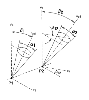
FIG. 2 is a view showing a visual direction of a point image
according to the invention.
[0073]
Similarly to FIG. 1, two point images (P1, P2) are provided
in such a manner that center axes (Vol, Vo2) of conical visible
27
I
t CA 02763053 2011-11-22
GNC10019CA
regions of the respective point images (P1, P2) incline and the
inclination angles (P1, 132) of the respective center axes (Vol,
Vo2) are defined by angles between vertical lines (Vp) extending
from the respective point images (P1, P2) with respect to the
surface of retroreflective sheeting and the center axes (Vol,
Vo2) of the respective conical visible regions. The respective
conical visible regions have dimensions (al, a2) .
[0074]
An angle formed between an azimuth (81) and an azimuth (Ã2)
of the respective center axes (Vol, Vo2) of the two point images
(P1, P2) is indicated by Ã12 (AO . The angle (Ã12) is equivalent
to an angle between a plane containing the vertical line (Vp)
and the axis (Vol) and a plane containing the vertical line (Vp)
and the axis (Vo2) . On the other hand, all center axes of point
images according to the conventional technique have the same
azimuth, and thus Ã12 is zero.
[0075]
FIGS. 3A and 3B are perspective views showing a
retroreflective sheeting provided with set images each having
a visual direction according to an embodiment of the invention.
[0076]
As shown in FIG. 3A, on a retroreflective sheeting 100,
a sinusoidal set image (L1) is made. The inclination direction
of a center axis (Vol) of the visible region of the point images
constituting the set image inclines leftward as shown in FIG.
28
I
µ CA 02763053 2011-11-22
GNC 10019CA
3A with respect to the vertical line (Vp) to the retroreflective
sheeting.
[0077]
As shown in FIG. 3B, on the retroreflective sheeting 100,
a sinusoidal set image (L2) adjacent to the set image (L1) is
also made. The inclination direction of a center axis (Vo2)
of the visible region of the point images constituting the set
image (L2) inclines rightward in FIG. 3B with respect to the
vertical line (Vp) to the retroreflective sheeting. In other
words, the center axis (Vol) and the center axis (Vo2) incline
in opposite directions with respect to the vertical line (Vp).
[0078]
In addition, inclination angles of the center axes in the
visible regions of the point images respectively in the set
images (L1 and L2) are set to 45 degrees or less with respect
to the vertical line (Vp), and the difference (AN between the
inclination angles of the center axes in the visible regions
of the point images respectively in the set images (L1 and L2)
adjacent to each other is set to range of between 5 and 25 degrees.
The set image (L2) is made to have a shape same as that of the
set image (L1) with a phase difference. The phase difference
is set to a quarter of a period of a sinusoidal wavelength.
[0079]
FIGS. 4A, 4B, and 4S are views for illustrating the set
images (L1 and L2) on the retroreflective sheeting shown in FIGS.
3A and 3B.
29
I
. CA 02763053 2011-11-22
GNC10019CA
[0080]
FIG. 4A is a plan view of the sinusoidal set image (L1)
shown in FIG. 3A, and FIG. 4B shows a plan view of the sinusoidal
set image (L2) shown in FIG. 35.
[0081]
FIG. 4S is a plan view in which the set image (L1) and the
set image (L2) are made to be superimposed. However, the two
set images (L1 and L2) are never viewed together from the same
view angle. When the set images (L1 and L2) are viewed while
oscillating, the set images (L1 and L2) are viewed alternately,
and can be viewed as a sinusoidal set image moving laterally
with afterimages.
[0082]
Next, a principle for the fact that the center axis (Vol)
of the visible region of the set image (L1) and the center axis
(Vo2) of the visible region of the set image (L2) are different
from each other will be described.
[0083]
FIG. 5 is a sectional view showing retroreflection on the
retroreflective sheeting of FIGS. 3A and 3B. Specifically, FIG.
is a sectional view in a region where the set image (L1) and
the set image (L2) shown in FIGS. 4A, and 4B intersect with each
other. It should be noted that the retroreflective sheeting
100 of the invention is not limited to the retroreflective
sheeting shown in FIG. 5, but an open lens micro glass sphere
retroreflective sheeting, an enclosed lens micro glass sphere
CA 02763053 2011-11-22
GNC10019CA
retroreflective sheeting or a capsular lens micro glass sphere
retroreflective sheeting described above, or combination
thereof may be used.
[0084]
As shown in FIG. 5, the retroreflective sheeting 100
includes: a surface protective layer 70; a holding layer 60 on
one surface of the surface protective layer 70; a microlens layer
50 including a plurality of microlenses 51 held on a surface
of the holding layer 60 opposite to the surface protective layer
70; a specularly reflective layer 30 provided on the microlens
layer 50 opposite to the holding layer 60; a focus forming layer
40 provided between the respective microlenses 51 and the
specularly reflective layer 30; an adhesive layer 20 provided
on a surface of the specularly reflective layer 30 opposite to
the microlens layer 50; and a protective sheet 10 protecting
the adhesive layer 20. A printed layer on which a predetermined
pattern is appropriately printed may be provided between the
surface protective layer 70 and the holding layer.
[0085]
The surface protective layer 70 is made of a light
transmissive resin in a shape of flat film.
[0086]
The holding layer 60 is light transmissive and into which
the microlenses 51 are embedded up to substantially the center
of the microlenses 51 from the opposite side of the surface
protective layer 70.
31
1
µ CA 02763053 2011-11-22
GNC10019CA
[0087]
The plurality of microlenses 51 of the microlens layer 50
are respectively embedded into the holding layer 60 up to
substantially the center thereof as described above so that
halves of their surfaces are covered by the holding layer 60.
In addition, portions of the microlenses 51 that are not covered
by the holding layer 60 are covered by the focus forming layer
40.
[0088]
The specularly reflective layer 30 is provided on a surface
of the focus forming layer 40. The surface of the specularly
reflective layer 30 on the side of the microlenses 51 and
surfaces of the respective microlenses 51 oppose to each other
with a certain distance through the focus forming layer 40 so
that reflection regions 31 are formed.
[0089]
On the reflection regions 31 in positions where the set
image (L1) is made in the specularly reflective layer 30, missing
parts 35a of a dot shape are formed on one side with respect
to the centers of the respective microlenses 51. Each of the
missing parts 35a is formed at the same position on each of the
reflection regions 31 opposing each of the microlenses 51 in
positions where the set image (L1) is made. On the reflection
regions 31 in positions where the set image (L2) is made in the
specularly reflective layer 30, missing parts 35b of a dot shape
are formed on the other side with respect to the centers of the
32
CA 02763053 2011-11-22
GNC 10019CA
respective microlenses 51. Each of the missing parts 35b is
formed at the same position on each of the reflection regions
31 opposing each of the microlenses 51 in positions where the
set image (L2) is made.
[0090]
FIG. 5 is a sectional view of the region where the set image
(L1) and the set image (L2) intersect with each other as
described above. Therefore, the missing parts 35a and 35b of
a dot shape are respectively formed on reflection regions 31
opposing the same microlenses 51. In FIG. 5, the reflection
regions 31 in the positions where the set image (L1) and the
set image (L2) are made, and the reflection regions 31 in
positions where the missing parts 35a or 35b are not formed are
shown.
[0091]
The adhesive layer 20 provided on the side of the
specularly reflective layer 30 opposite to the microlens layer
50 is provided in order to attach the retroreflective sheeting
100 to another' object that is not shown. The protective sheet
protects the adhesive layer 20 until the retroreflective
sheeting 100 is attached to another object.
[0092]
Materials of each of the members included in the
retroreflective sheeting 100 will be described.
[0093]
The surface protective layer 70 is made of vinyl chloride
33
I
. CA 02763053 2011-11-22
GNC10019CA
resin. The holding layer 60 is made of acrylic resin. The
microlenses 51 are made of glass. The focus forming layer 40
is made of acrylic resin. The specularly reflective layer 30
is made of deposited aluminum. The adhesive layer 20 is made
of acrylic resin.
[0094]
The way of making the set image (L1) and the set image (L2)
on the retroreflective sheeting 100 will be described.
[0095]
As shown in FIG. 5, lights L enter the retroreflective
sheeting 100 from the surface protective layer 70 side of the
retroreflective sheeting 100 in a direction having a
predetermined inclination angle with respect to a direction
vertical to the surface of the retroreflective sheeting 100.
The lights L entering the retroreflective sheeting 100 are
refracted at the surface of the microlenses 51 and output from
the microlenses 51. The lights L output from the microlenses
51 are focused at the respective reflection regions 31 on the
specularly reflective layer 30. The focused lights are
reflected at the reflection regions 31 so as to enter the
microlenses 51 again. Then, the lights L are refracted at the
surface of the microlenses 51 and output from the microlenses
51. At this time, the lights L are output to a direction having
an inclination angle, which is the same as that when the lights
L enter the retroreflective sheeting 100, with respect to the
direction vertical to the surface of the retroreflective
34
CA 02763053 2011-11-22
GNC10019CA
sheeting 100. Therefore, the retroreflective sheeting 100
reflects the lights irradiated from a light source toward the
light source. At this time, as long as the lights focused at
the respective reflection regions 31 on the specularly
reflective layer 30 are not focused at the missing parts 35a
or the missing part 35b, the focused lights are also reflected
in the reflection regions 31 where the missing parts 35a and
35b are formed as shown in FIG. 5. Therefore, an observer
observing the retroreflective sheeting 100 from the direction
same as that of the lights L cannot view the set images (L1 and
L2).
[0096]
FIG. 6 is a sectional view showing retroreflection by which
the set image shown in FIG. 3A is made. When lights entering
the microlenses 51 to form the set image (L1) among lights L
entering the retroreflective sheeting 100 from the center axis
(Vol), which are lights L entering with an inclination angle
(pi) with respect to the vertical line (Vp) to the surface of
the retroreflective sheeting 100, are focused on surfaces of
the reflection regions 31 of the specularly reflective layer
30, they are focused at the missing parts 35a of a dot shape
on the reflection regions 31 so as not to be reflected as shown
in FIG. 6. Therefore, when the lights L enter from a direction
having an inclination angle (31) with respect to the vertical
line (Vp) to the surface of the retroreflective sheeting 100,
retroreflected lights are missing at the positions where the
I
= CA 02763053 2011-11-22
GNC10019CA
set image (L1) is made as depicted by a dashed line in FIG. 6
so as to form point images (P1) respectively forming the set
image (L1). On the other hand, at positions where the set image
(L1) is not formed, the lights L entering the microlenses 51
are reflected at the specularly reflective layer 30 so as to
be output in a direction having an inclination angle (p1) with
respect to the vertical line (Vp) to the surface of the
retroreflective sheeting 100, which is a direction along the
center axis (Vol). Accordingly, an observer observing the
retroreflective sheeting 100 along the center axis (Vol) can
view the set image (L1) as a comparatively dark set image (L1)
on the specularly reflective layer 31.
[0097]
FIG. 7 is a sectional view showing retroreflection by which
the set image shown in FIG. 3B is made. When lights entering
the microlenses 51 to form the set image (L2) among lights L
entering the retroreflective sheeting 100 from the center axis
(Vo2), which are lights L entering with an inclination angle
(132) with respect to the vertical line (Vp) to the surface of
the retroreflective sheeting 100, are focused on surfaces of
the reflection regions 31 of the specularly reflective layer
30, they are focused at the missing parts 35b of a dot shape
on the reflection region 31 so as not to be reflected as shown
in FIG. 7. Therefore, when the lights L enter from a direction
having an inclination angle (132) with respect to the vertical
line (Vp) to the surface of the retroreflective sheeting 100,
36
1
= CA 02763053 2011-11-22
GNC 10019CA
retroreflected lights are missing at the positions where the
set image (L2) is made as depicted by a dashed line in FIG. 7
so as to form point images (P2) respectively forming the set
image (L2). On the other hand, at positions where the set image
(L2) is not formed, the lights L entering the microlenses 51
are reflected at the specularly reflective layer 30 so as to
be output in a direction having an inclination angle (132) with
respect to the vertical line (Vp) to the surface of the
retroreflective sheeting 100, which is a direction along the
center axis (Vo2). Accordingly, an observer observing the
retroreflective sheeting 100 along the center axis (Vo2) can
view the set image (L2) as a comparatively dark set image (L2)
on the specularly reflective layer 31.
[0098]
The dimensions (al, a2) of the conical visible regions
may be appropriately changed by changing the size of the missing
parts 35a and 35b of a dot shape.
[0099]
Next, another embodiment of the invention will be
described. FIGS. 8A to 8C are perspective views showing a
retroreflective sheeting provided with set images each having
a visual direction according to another embodiment of the
invention. As shown in FIG. 8A, on a retroreflective sheeting
100, a sinusoidal set image (L1) is made. The inclination
direction of a center axis (Vol) of the visible region of the
point images constituting the set image inclines leftward in
37
I
CA 02763053 2011-11-22
GNC 10019CA
FIG. 8A with respect to a vertical line (Vp) to the
retroreflective sheeting.
[0100]
As shown in FIG. 8B, on the retroreflective sheeting 100,
a sinusoidal set image (L2) adjacent to the set image (L1) is
made. The inclination direction of a center axis (Vo2) of the
visible region of the point images constituting the set image
(L2) aligns with the vertical line (Vp) to the retroreflective
sheeting 100. In addition, the set image (L2) is made to have
a shape same as that of the set image (L1) with a phase difference.
The phase difference is set to a sixth part of a period of a
sinusoidal wavelength.
[0101]
As shown in FIG. 8C, on a retroreflective sheeting 100,
a sinusoidal set image (L3) is made. The inclination direction
of a center axis (Vo3) of the visible region of the point images
constituting the set image (L3) inclines rightward in FIG. 8C
with respect to the vertical line (Vp) to the retroreflective
sheeting 100. In other word, the center axis (Vol) and the
center axis (Vo3) incline in opposite directions with respect
to the vertical line (Vp). In addition, the set image (L3) is
made to have a shape same as that of the set image (L1) with
a phase difference. The phase difference is set to two sixths
of a period of a sinusoidal wavelength.
[0102]
In addition, inclination angles of the center axes in the
38
I
. CA 02763053 2011-11-22
GNC10019CA
visible regions of the point images in the respective set images
(L1, L2, L3) are set to 45 degrees or less with respect to the
vertical line (Vp), and the difference (AP) between the
inclination angles of the center axes in the visible regions
of the point images respectively in the set images (L1, L2, L3)
adjacent to each other is set to range of between 5 and 25 degrees.
[0103]
FIGS. 9A to 9C and 9S are views showing the set images (L1,
L2, L3) on the retroreflective sheeting 100 shown in FIG. 8A
to 8C.
[0104]
FIG. 9A is a plan view of the sinusoidal set image (L1)
shown in FIG. 8A, FIG. 9B is a plan view of the sinusoidal set
image (L2) shown in FIG. 8B, and FIG. 9C is a plan view of the
sinusoidal set image (L3) shown in FIG. 8C.
[0105]
FIG. 9S is a plan view in which the three sinusoidal set
images (L1, L2, and L3) are made to be superimposed. However,
the three set images (L1, L2, and L3) are never viewed together
from the same view angle. When the set images (L1, L2, and L3)
are viewed while oscillating, the set images (L1, L2, and L3)
are viewed alternately, and can be viewed as a sinusoidal set
image moving laterally with afterimages.
[0106]
FIGS. 10A to 10C and 10S are views showing set images
according to still another embodiment of the invention.
39
1
CA 02763053 2011-11-22
GNC10019CA
[0107]
FIGS. 10A, 10B, and 100 are a combination of elliptical
set images that can be observed from different view angles. The
set images shown in FIGS. 10A, 10B, and 100 are arranged in a
vertical direction in FIGS. 10A, 10B, and 100. These set images
may have the same or homologous shapes.
[0108]
From a fixed view angle, an observer can observe only one
of these set images, but cannot observe other set images. To
observe another set image, the observer has to move the viewpoint
to a different view angle and then observe. From the different
fixed view angle, other two images cannot be observed similarly.
[0109]
In FIGS. 10A to 100 and 10S, three set images are provided
in combination in such a manner that inclination angles of the
center axes in the visible regions of the point images
respectively in the set images shown in FIGS. 10A, 10B, and 100
are set to 45 degrees or less with respect to the vertical line
to the retroreflective sheeting, and the difference (An) between
the inclination angles of the center axes in the visible regions
of the point images respectively in the set images shown in FIGS.
10A, 10B, and 10C adjacent to each other is set to range of between
and 25 degrees, and preferably set to 8 to 22 degrees. When
the retroreflective sheeting is oscillated in the direction of
the inclination angle of the center axis so as to view the images
while oscillating, the combination of the three set images can
CA 02763053 2011-11-22
GNC 10019CA
provide an effect showing as if an object were moving up and
down with afterimages to the observer. The observer would view
an image as if a ball were bouncing up and down.
[0110]
A retroreflective sheeting provided with meaningless set
images in combination can show moving image phenomenon by being
viewed while oscillated under specific conditions, and thus can
provide preferable anticounterfeit characteristic.
[0111]
FIGS. 11A to 110 and 11S are views showing set images
according to still another embodiment of the invention.
[0112]
FIGS. 11A, 11B, and 110 are a combination of elliptical
set images that can be observed from different view angles. The
set images shown in FIGS. 11A, 11B, and 110 are arranged in an
oblique direction in FIGS. 11A, 11B, and 11C with phase
differences. These set images may have the same or homologous
shapes.
[0113]
From a fixed view angle, an observer can observe only one
of these set images, but cannot observe other set images. To
observe another set image, the observer has to move the viewpoint
to a different view angle and then observe. From the different
fixed view angle, other two images cannot be observed similarly.
[0114]
In FIGS. 11A to 110 and 11S, three set images are provided
41
CA 02763053 2011-11-22
GNC10019CA
in combination in such a manner that inclination angles of the
center axes in the visible regions of the point images
respectively in the set images shown in FIGS. 11A, 11B, and 11C
are set to 45 degrees or less with respect to the vertical line
to the retroreflective sheeting, and the difference (AP) between
the inclination angles of the center axes in the visible regions
of the point images respectively in the set images shown in FIGS.
11A, 11B, and 11C adjacent to each other is set to range of between
and 25 degrees, and preferably set to 8 to 22 degrees. When
the retroreflective sheeting is oscillated in the direction of
the inclination angle of the center axis so as to view the images
while oscillating, the combination of the three set images can
provide an effect showing as if an object were moving side to
side and up and down with afterimages to the observer. The
observer would view an image as if a ball were bouncing in lateral
direction.
[0115]
A retroreflective sheeting provided with meaningless set
images in combination can show moving image phenomenon by being
viewed while oscillated under specific conditions, and thus can
provide preferable anticounterfeit characteristic similar to
the embodiment shown in FIGS. 10A to 10C and 105.
[0116]
FIGS. 12A to 12C and 12S are views showing set images
according to still another embodiment of the invention.
[0117]
42
CA 02763053 2011-11-22
GNC10019CA
FIGS. 12A, 12B, and 12C are a combination of set images
of meaningless shapes that can be observed from different view
angles. From a fixed view angle, an observer can observe only
one of these set images, but cannot observe other set images.
To observe another set image, the observer has to move the
viewpoint to a different view angle and then observe. From the
different fixed view angle, other two set images cannot be
observed similarly.
[0118]
In FIGS. 12A to 12C and 12S, three set images are provided
in combination in such a manner that inclination angles of the
center axes in the visible regions of the point images
respectively in the set images shown in FIGS. 12A, 12B, and 12C
are set to 45 degrees or less with respect to the vertical line
to the retroreflective sheeting, and the difference (AP) between
the inclination angles of the center axes in the visible regions
of the point images respectively in the set images shown in FIGS.
12A, 12B, and 12C adjacent to each other is set to range of between
and 25 degrees, and preferably set to 8 to 22 degrees. When
the retroreflective sheeting is oscillated in the direction of
the inclination angle of the center axis so as to view the images
while oscillating, the combination of the three set images
combined with set images provided adjacent to each other can
provide an effect showing an image with meaning shown in FIG.
12S that is different from individual set images with
afterimages to the observer.
43
1
, CA 02763053 2011-11-22
GNC10019CA
[0119]
A retroreflective sheeting provided with meaningless set
images in combination can show information with meaning by being
viewed while oscillated under specific conditions so as to
provide preferable anticounterfeit characteristic.
Industrial Applicability
[0120]
As specific use of a retroreflective sheeting according
to the invention, the retroreflective sheeting can be used as
a retroreflective sheeting that can be used for a traffic sign,
a construction sign, a commercial sign, a vehicle registration
plate, a retroreflective sticker, a retroreflective RFID tag,
and the like and that has excellent anticounterfeit
characteristic and information providing characteristic.
[0121]
An article according to the invention is a retroreflective
sheeting that is provided with an image having a visual direction
and has excellent anticounterfeit characteristic so that the
retroreflective sheeting can be used for a sign, label and the
like, on which a retroreflective sheeting provided with an image
having anticounterfeit characteristic is attached.
[0122]
In addition, a sign, a label, or the like can be an
authentication mark that is difficult to be counterfeited by
attaching a retroreflective sheeting according to the
44
I
CA 02763053 2011-11-22
GNC 10019CA
invention.
Description of Reference Numerals
[0123]
_ protective sheet
_ adhesive layer
_ specularly reflective layer
31 _ reflection region
35a, 35b _ missing part
_ focus forming layer
_ microlens layer
51 _ microlens
_ holding layer
_ surface protective layer
100 _ retroreflective sheeting
P, Pl, P2 _ point image
Vp _ vertical line
Vo _ center axis
Vol, Vo2, Vo3 _ center axis
L _ light
Li, L2, and L3 _ set image