Note: Descriptions are shown in the official language in which they were submitted.
CA 02763103 2011-11-22
PCT/DE2010/050015
Eccentric adjusting element
and eccentric disc for said eccentric adjusting element
Description
Technical field
[0001] The present invention relates to an eccentric adjusting element and to
an
eccentric disc for said eccentric adjusting element, and to a method for the
production of
an eccentric adjusting element of this type.
Prior art
[0002] Eccentric adjusting elements are enjoying an ever increasing popularity
in
the automotive industry, in particular for the realisation of the adjustment
functions on
the chassis.
[0003] These eccentric adjusting elements originally comprised a bolt-type
screw
with an eccentric disc firmly attached directly below the head and an external
thread
which was interrupted by a profiling so that the second eccentric disc could
be fitted onto
this profiling with a defined angular position of eccentricity. The entire
eccentric adjusting
element was then secured or fixed by screwing a nut onto the external thread.
[0004] However, early on it was found that the corresponding external threads
in-
terrupted by a profiling are dangerous because, when loaded, they have unusual
charac-
teristics; in particular they suddenly fracture as the load increases, whereas
continuous
external threads exhibit a normal load behaviour.
[0005] Therefore, the eccentric adjusting elements with an external thread
inter-
rupted by a profile were set aside in favour of solutions in which the
profiling and external
thread are arranged separately on the shank of the bolt-type screw. In these
solutions,
CA 02763103 2011-11-22
-2-
provided approximately in the central region of the bolt is a profiling for
attaching the
second eccentric disc and towards the end of the bolt, an external thread
adjoins this pro-
filed portion, said external thread then being used for screwing on a nut.
[0006] Corresponding adjusting elements are known, for example from FR 2720
845 Al.
[0007] Eccentric adjusting elements also exist in which both discs are fitted
onto a
profiled shank. The profiling then either runs over the entire shank of the
screw, as in DE
20 2007 0064 10 U 1 or, provided on both ends of a headless rod are a
respective profiled
portion and an external thread at the end thereof, as in DE 20 2007 013 473
U1.
[0008] Particularly preferred configurations of the profiling are found in DE
20
2009 000 623 U 1.
[0009] All of these solutions suffer from the problem that the nut cannot be
screwed over the profiling. Therefore, the attached eccentric element cannot
be tightened
and fixed with a normal nut. Instead, as presented in each of the above-
mentioned doc-
uments, a specifically configured nut is required for this purpose in which a
tubular or hol-
low-cylindrical shoulder is provided which has a significantly larger internal
diameter than
the internal thread of the nut so that when the nut is tightened, said
shoulder can engage
over the profiling and can there exert the necessary pretensioning force onto
the eccen-
tric disc.
[0010] The production of nuts of this type is very expensive because they have
to
be produced as specific parts. In particular, it is difficult to realise the
different internal
diameters for the hole of the internal thread and for that part of the hole
and furthermore
the region over which the profile with a significantly larger internal
diameter engages has
to be adjusted to the respective case of use.
Presentation of the invention
[0011] Therefore, it is the object of the present invention to make it
possible to
use normal commercially available standard nuts in the above-mentioned
eccentric adjust-
ing elements, instead of the specific parts which have been conventional
hitherto. Up until
now, it has been a major advantage of eccentric adjusting elements or
eccentric adjusting
screws provided with profilings cut into the external thread that the much
cheaper and
more readily available standard nuts could be used in this case.
CA 02763103 2011-11-22
-3-
[0012] This object is achieved according to the invention by an eccentric
adjusting
element comprising a pin with at least one free end having a profiled portion
and an ex-
ternal thread which adjoins at the end thereof and has a relatively small
external diame-
ter, in which eccentric adjusting element an eccentric disc is fitted onto the
profiled por-
tion and is secured by a nut which is screwed onto the external thread, in
that a hollow
cylindrical or tubular spacer is attached between the eccentric disc and the
nut.
[0013] A particularly simple production of the spacer is provided when the
spacer
is inserted loosely between the eccentric disc and the nut. A correspondingly
cut tubular
piece is then satisfactory as the spacer.
[0014] However, a simpler assembly (fewer individual parts) is provided when
the
spacer is rigidly connected to the eccentric disc.
[0015] Recommended methods for connecting the spacer to the eccentric disc are
adhesive bonding, caulking or welding methods.
[0016] A further preferred solution is that the spacer itself is provided
internally
with a counter profile matching the profile of the profiled portion and is
pressed into a re-
cess in the eccentric disc. In this manner, it is possible to produce
different angular posi-
tions of eccentricity between the profile and the eccentric disc with only one
eccentric disc
and only one spacer in that the spacer which alone bears the profile is
pressed, bonded
or welded into the eccentric disc at the respectively desired angle.
[0017] A particularly high flexibility with respect to the angular
relationships to be
realised between the profile in the spacer and the eccentricity of the
eccentric disc is pro-
vided when the spacer is configured to be circular on the outside and when the
recess in
the eccentric disc is also configured to be circular.
[0018] However, if a transmission of force is desired between spacer and
eccentric
disc which is as optimum as possible, it is recommended to configure the
exterior of the
spacer as a polygon, preferably as a square or hexagon and to configure the
recess in the
eccentric disc corresponding to t he external shape of the spacer.
[0019] The object according to the invention which has been described above
can
also be achieved with conventional eccentric adjusting elements when merely an
eccentric
disc according to the invention is used which is provided with a hollow
cylindrical or tubu-
lar spacer.
[0020] In this respect, the spacer is preferably adhesively bonded, caulked or
welded to the eccentric disc.
CA 02763103 2011-11-22
-4-
[0021] Here as well it is preferred to provide the interior of the spacer with
a pro-
file and to press, bond or weld the spacer into a recess in the eccentric disc
if an optimum
flexibility is desired in respect of the association between eccentricity of
the disc and a n-
gular position of the profile.
[0022] In order to be able to realise a large number of very different angular
posi-
tions of this type, it is particularly preferred for the exterior of the
spacer to be circular
and for the recess in the eccentric disc also to be circular.
[0023] However, if the best possible transmission of force is desired between
spacer (and thus the profile) and the eccentric disc, it is particularly
preferred for the ex-
terior of the spacer to be configured as a polygon, preferably as a square or
hexagon and
for the recess in the eccentric disc to be configured corresponding to the
external shape
of the spacer.
[0024] The spacer can preferably be inserted into the eccentric disc and
caulked,
welded or adhesively bonded therein.
[0025] In the following, the present invention will be described in more
detail with
reference to the embodiments illustrated in the drawings.
Brief description of the drawings
[0026] Fig. 1 shows an eccentric adjusting element according to the invention,
where an eccentric disc with an integrally form ed spacer is used;
[0027] Fig. 2 shows a further eccentric adjusting element according to the
inven-
tion with a spacer loosely inserted between eccentric disc and nut;
[0028] Fig. 3 shows an eccentric adjusting element according to the invention
with
a spacer inserted into the eccentric disc, each in a partially sectional view
from the side;
[0029] Fig. 4 shows an eccentric adjusting element according to Fig. 1, 2 or
3,
seen from the nut side;
[0030] Fig. 5 shows the section A-A according to Fig. 1 or 2; and
[0031] Fig. 6 shows the section B-B from Fig. 3.
Best method for implementing the invention
CA 02763103 2011-11-22
-5-
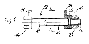
[0032] Fig. 1 shows an embodiment of an eccentric adjusting element 10 accord-
ing to the invention with an eccentric screw 12 having a hexagonal head 14
which directly
merges into a first eccentric disc 16. Adjoining this eccentric disc 16 is a
circular shank 18
which is provided with a profiling 20 in a central region between the head 14
and the end
of said shank 18. An external thread 22 with a relatively small external
diameter adjoins
the profiling 20 towards the end of the shank 18.
[0033] Instead of the eccentric screw 12 described here, an eccentric screw
with a
fully profiled shank can also be provided for the present invention, in which
case the first
eccentric disc 16 is not produced integrally with the head 14 or pressed or
caulked onto
the shank 18, but is also fitted onto the profile.
[0034] Similarly, the present invention can also be used in the case of an
eccentric
rod; here, instead of the head 14 and the first eccentric disc 16, in a mirror-
inverted
manner to the profiling and to the external thread shown here, the same
construction is
provided at the other end of the rod. Corresponding eccentric rods are known,
for exam-
ple from DE 20 2007 013 473 U1, to which reference is hereby made with respect
to the
description of an eccentric rod as such.
[0035] An eccentric screw with a profiling which extends over the entire shank
and
with two attached eccentric discs is known, for example from DE 20 2007 006
410 U 1.
[0036] However, in Fig. 1, unlike the prior art mentioned above, a simple
second
eccentric disc is not fitted onto the profiling 20. Instead, a specific second
eccentric disc
24 is provided here which has, in a known manner, a hole or a punch-out which
is pro-
vided with a counter profile to the profile 20.
[0037] According to the invention, a tubular, i.e. hollow cylindrical shoulder
26 is
attached in one piece to the eccentric disc 24. This shoulder 26 has the same
internal di-
ameter as the hole or punch-out in the eccentric disc 24. It can optionally
also be pro-
vided with the same profiling, although this is not compulsory for the
operation of the
present invention.
[0038] However, unlike the prior art, a specific nut with a hollow cylindrical
shoul-
der for screwing down the second eccentric disc 24 is not required. According
to the in-
vention, the shoulder 26 extends right up into the region of the external
thread 22 and in
this way the second eccentric disc 24 can be secured by screwing on a
commercially
available standard nut 28. Thus, it is now possible for the first time to use
a commercially
available standard nut 28 for securing or screwing down the eccentric disc 24
in the case
CA 02763103 2011-11-22
-6-
of an eccentric adjusting element with a profiling which is spatially
separated from the ex-
ternal thread. According to the invention, the nut 28 no longer has to be able
to partially
engage over the profiled portion 20 in addition to the external thread 22.
Method(s) for implementing the invention
[0039] Fig. 2 shows a further embodiment of the present invention. Here, the
same eccentric screw 12 is used in the illustrated example as in Fig 1. In
this respect, ref-
erence is made to the description of the eccentric screw in Fig. 1; the same
features are
characterised by the same reference signs.
[0040] In this further embodiment according to the invention, an eccentric
disc
124 which is already known from the prior art and has a matching profiled hole
or punch-
out is fitted onto the profiling 20 of the shank 18 of the eccentric screw 12.
[0041] However, according to the invention, the commercially available
standard
nut 28 illustrated in Fig. 1 can also be used here for securing and screwing
down the
second eccentric disc 124.
[0042] This is achieved according to the invention in that in the present
embodi-
ment, a hollow cylindrical spacer 126, i.e. a spacer which corresponds in
shape to a short
tubular portion, is introduced between the eccentric disc 124 corresponding to
the prior
art and the nut 28. This spacer 126 merely needs to have an adequately large
internal di-
ameter. It does not need to have a profiling. Thus, the production of a spacer
126 of this
type is extremely simple.
[0043] Fig. 3 shows a further embodiment of the present invention. Here as
well,
the eccentric screw 12 known from the prior art is used, as is described in
detail in Fig. 1.
The same reference signs again denote the same components.
[0044] In this embodiment of the present invention as well, a specific second
ec-
centric disc 224 is fitted onto the profiling 20 of the shank 18 of the
eccentric screw 12.
However, in the present case, the eccentric disc 224 consists of two parts. It
comprises
the actual eccentric disc which, however, in this embodiment is provided with
a relatively
large punch-out. Inserted by pressing, adhesively bonding or welding into this
larger
punch-out is a hollow cylindrical element 226 which has a coaxial inner hole
provided with
a counter profile which matches the profile 20. The spacer 226 has a circular
or polygo-
nally configured outer contour at least in the region with which this spacer
226 is inserted
CA 02763103 2011-11-22
-7-
into the eccentric disc 224. The disc 224 has a punch-out or hole with a
corresponding in-
ternal diameter and a matching inner contour. The region of the spacer 226
which is in-
serted into the disc 224 can have a relatively large diameter and/or a
different outer con-
tour to avoid errors during insertion, for example an insertion which is too
deep or obli-
que, in the region which is not to be inserted into the disc 224, so that a
stop stage 228
is formed, against which the disc 224 rests after assembly of disc 224 and
spacer 226.
[0045] The combination, provided here, of second eccentric disc 224 and spacer
226 can be screwed down and secured by a commercially available standard nut
28 which
is screwed onto the external thread 22 of the eccentric screw 12.
[0046] Fig. 4 shows a view of the embodiments of the invention according to
Fig.
1, 2 or 3 from the nut side, i.e. seen from the free end of the shank 18 of
the screw 12. It
should be noted that this view is identical for all embodiments according to
Fig. 1, 2 or 3.
[0047] Fig. 4 shows how the second eccentric disc 24/124/224 is screwed down
and secured by a commercially available nut 28 which is screwed onto the
external thread
22 of the shank 18 of the screw 12.
[0048] Fig. 5 shows a view along the section A-A of Fig. 1 or 2. It should be
noted
that the two sectional views are identical.
[0049] It can be seen here how the eccentric disc 24 or 124, provided with a
pro-
file according to DE 20 2009 000 623 U 1 is fitted onto the shank 18 provided
with a coun-
ter profile which is also configured according to DE 20 2009 000 623 Ul.
[0050] Fig. 6 shows the section B-B from Fig. 3.
[0051] Here again it is possible to see the cut shank 18 of the eccentric
screw 12
with the profile 20 according to DE 20 2009 000 623 U1. However, the
corresponding
counter profile is configured in the spacer 226 which, in this embodiment,
extends
through the eccentric disc 224. For this purpose, the eccentric disc 224 is
provided here
with a correspondingly larger hole or punch-out. At least the end of the
spacer 226 di-
rected towards the observer is provided with a corresponding outer contour. In
the illu-
strated embodiment, this is a hexagonal contour. However, other polygonal
contours are
also possible according to the invention, for example a square contour.
Furthermore, the
outer contour of the spacer 226 can also be circular for other specific cases
of use. The
circular configuration allows a free association of the eccentricity of the
disc 224 with the
position of the counter profile in the spacer 226, while a configuration of
the outer con-
tour of the spacer 226 as a polygon allows a much better transmission of force
onto the
CA 02763103 2011-11-22
-8-
disc 224 between the spacer 226 and thus the profile 20, and therefore the
screw 12, but
at the cost that merely specific angular stages are still possible during the
association be-
tween eccentricity of the disc 224 and profile 20.