Note: Descriptions are shown in the official language in which they were submitted.
CA 02763152 2012-01-04
SYSTEM AND METHOD FOR MEASURING CURRENT OF AN \/
ELECTROSURGICAL GENERATOR
BACKGROUND
Technical Field
[0001] The present disclosure relates to a system and method for performing
electrosurgical procedures. More particularly, the present disclosure relates
to a system and
method for measuring current of an electrosurgical generator using the voltage
across a DC
blocking capacitor.
Background of Related Art
[0002] Electrosurgery involves application of radio frequency electrical
current (e.g.,
electrosurgical energy) to a surgical site to cut, ablate, coagulate, or seal
tissue. In
electrosurgery, a source or active electrode delivers electrosurgical energy
from the
electrosurgical generator to the tissue and a return electrode carries the
current back to the
generator. In monopolar electrosurgery, the source electrode is typically part
of the surgical
instrument held by the surgeon and is applied to the tissue to be treated.
In bipolar electrosurgery, the return electrode is part of a patient return
pad positioned
remotely from the active electrode on the patient's body to carry the current
back to the
generator.
[0003] Ablation is a monopolar procedure which is particularly useful in
the field of
neurosurgery and cancer tumor hyperthermia, where one or more RF ablation
needle
electrodes (usually of elongated cylindrical geometry) are inserted into a
living body. A
1
CA 02763152 2012-01-04
typical form of such needle electrodes incorporates an insulated sheath from
which an
exposed (uninsulated) tip extends. When RF energy is provided between the
return electrode
and the inserted ablation electrode. RF current flows from the needle
electrode through the
body. Typically, the current density is very high near the tip of the needle
electrode, which
tends to heat and destroy surrounding tissue.
[0004] In bipolar electrosurgery, one of the electrodes of the hand-held
instrument
functions as the active electrode and the other as the return electrode. The
return electrode is
placed in close proximity to the active electrode such that an electrical
circuit is formed
between the two electrodes (e.g., electrosurgical forceps). In this manner,
the applied
electrical current is limited to the body tissue positioned between the
electrodes. When the
electrodes are sufficiently separated from one another, the electrical circuit
is open and thus
inadvertent contact with body tissue with either of the separated electrodes
does not cause
current to flow.
SUMMARY
[0005] In one embodiment of the present disclosure, an electrosurgical
generator is
adapted to supply the energy to the at least one active electrode. The
electrosurgical generator
includes an RF output stage, a DC blocking capacitor, a measuring circuit, and
a sensor
circuit. The RF output stage generates the electrosurgical energy. The DC
blocking capacitor
is electrically coupled between the RF output stage and tissue. The
electrosurgical generator
can detect a fault of the DC blocking capacitor. The measuring circuit is
coupled to the DC
blocking capacitor and measures the voltage across the DC blocking capacitor.
The sensor
circuit determines the current of the electrosurgical energy as a function of
the voltage across
the DC blocking capacitor. In some embodiments of the present disclosure, the
system
determines the current of the electrosurgical energy in an absence of a
current sense
2
CA 02763152 2012-01-04
transformer to measure the current of the electrosurgical energy. Any of the
embodiments
disclosed herein of the electrosrugical generator may be used with an
electrosurgical system.
In an embodiment of the present disclosure, the electrosurgical generator may
be used with an
electrosurgical system that includes an electrosurgical instrument and the
electrosurgical
generator. The electrosurgical instrument includes at least one active
electrode adapted to
apply electrosurgical energy to tissue.
[0006] In an embodiment of the present disclosure, the generator further
includes a
first, second. third, and fourth capacitor. The DC blocking capacitor has
first and second
nodes and each of the first, second, third, and fourth capacitors has
respective first and second
nodes. The first capacitor's first node is coupled to the first node of the DC
blocking
capacitor. The second capacitor's first node is coupled between the second
node of the first
capacitor and a reference (e.g., ground). The third capacitor's first node is
coupled to the
second node of the DC blocking capacitor. The fourth capacitor's first node is
coupled
between the second node of the third capacitor and the reference. The sensor
circuit may be
coupled to the second node of the first capacitor and the second node of the
third capacitor to
determine the voltage therebetween to determine the current of the
electrosurgical energy as a
function of the voltage across the DC blocking capacitor.
[0007] In one embodiment of the present disclosure, the first capacitor has
a
capacitance that is about equal to a capacitance of the third capacitor. The
second capacitor
may have a capacitance that is about equal to the capacitance of the fourth
capacitor.
[0008] In yet another embodiment of the present disclosure, the sensor
circuit
determines the current utilizing the relationship of: I = C(dvidt). C is an
estimated
capacitance of the DC blocking capacitor, dv is the measure of the voltage
across the DC
blocking capacitor, and dt is a predetermined interval of the electrosurgical
energy. The DC
3
CA 02763152 2012-01-04
blocking capacitor may have a capacitance of around 50nF for bipolar energy
and 5nF for
monopolar energy.
[0009] In another embodiment of the present disclosure, an electrosurgical
generator
includes an RF output stage, a DC blocking capacitor, and measuring and sensor
circuits. The
RF output stage generates electrosrugical energy for application to an active
electrode. The
DC blocking capacitor is electrically coupled between the RF output stage and
the active
electrode. The measuring circuit is coupled to the DC blocking capacitor to
measure the
voltage across the DC blocking capacitor. The sensor circuit determines the
current of the
electrosurgical energy as a function of the voltage across the DC blocking
capacitor.
[0010] In an embodiment of the present disclosure, the electrosurgical
generator
includes fifth and sixth capacitors. The fifth capacitor is connected in
series or in parallel
with the first capacitor. The sixth capacitor is connected in series or in
parallel with the third
capacitor.
[0011] In another embodiment of the present disclosure, the electrosurgical
generator
includes a cut-off circuit. The cut-off circuit is coupled to the sensor
circuit to communicate
the determined current of the electrosurgical therefrom, wherein the cut-off
circuit is adapted
to stop the application of the electrosurgical energy to the active electrode
when the measured
current reaches a predetermined threshold. The electrosurgical generator may
further include
a switch coupled between the RF output stage and the active electrode. The cut-
off circuit
includes a comparator to compare the determined current to the predetermined
threshold and
to generate a cut-off signal adapted to signal the switch to stop the
application of the
electrosurgical energy to the active electrode.
[0012] In an embodiment of the present disclosure, a return electrode is
adapted to
return the electrosurgical energy. An another DC blocking capacitor is
electrically coupled
between the RF output stage and the return electrode. An another measuring
circuit is
4
CA 02763152 2012-01-04
coupled to the another DC blocking capacitor to measure the voltage across the
another DC
blocking capacitor. The sensor circuit determines the current of the return
electrosurgical
energy as a function of the voltage across the another DC blocking capacitor.
A leakage
current measuring circuit is coupled to the sensor to compare the current of
the electrosurgical
energy to the current of the return electrosurgical energy to measure a
leakage current.
BRIEF DESCRIPTION OF THE DRAWINGS
[0013] Various embodiments of the present disclosure are described herein
with
reference to the drawings wherein:
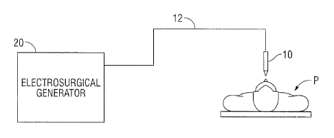
[0014] Fig. 1 is a schematic block diagram of an electrosurgical system
according to
the present disclosure;
[0015] F12. 2 is a schematic block diagram of an electrosurgical generator
according
to the present disclosure;
[0016] Fig. 3 shows a circuit coupled to a DC blocking capacitor that may
be used by
the generator of Figs. 1 or 2 according to the present disclosure; and
[0017] Fig. 4 shows a circuit coupled to a DC blocking capacitor and a
redundant DC
blocking capacitor for determining the current of the electrosurgical energy
according to the
present disclosure.
DETAILED DESCRIPTION
[0018] Particular embodiments of the present disclosure are described
hereinbelow
with reference to the accompanying drawings. In the following description,
well-known
functions or constructions are not described in detail to avoid obscuring the
present disclosure
in unnecessary detail. Those skilled in the art will understand that the
invention according to
the present disclosure may be adapted for use with either monopolar or bipolar
electrosurgical
CA 02763152 2012-01-04
systems. Fig. 1 is a schematic illustration of an electrosurgical system
according to the
present disclosure. The system includes an electrosurgical instrument 10
having one or more
electrodes for treating tissue of a patient P. The instrument 10 may be either
of monopolar
type including one or more active electrodes (e.g., electrosurgical cutting
probe, ablation
electrode(s), etc.) or of bipolar type including one or more active and return
electrodes (e.g.,
electrosurgical sealing forceps). Electrosurgical RF energy is supplied to the
instrument 10 by
a generator 20 via a supply line 12, which is operably connected to an active
output tenninal,
allowing the instrument 10 to coagulate, seal, ablate and/or otherwise treat
tissue.
[0019] If the instrument 10 is of monopolar type then energy may be
returned to the
generator 20 through a return electrode (not explicitly shown) which may be
one or more
electrode pads disposed on the patient's body. The system may include a
plurality of return
electrodes which are believed to minimize the chances of tissue damage by
maximizing the
overall contact area with the patient P. In addition, the generator 20 and the
monopolar return
electrode may be configured for monitoring the sufficiency of the so called
"tissue-to-patient"
contact impedance to further minimize chances of tissue damage.
[0020] If the instrument 10 is of bipolar type, the return electrode is
disposed in
proximity to the active electrode (e.g., on opposing jaws of bipolar forceps).
The generator 20
may include a plurality of supply and return terminals and a corresponding
number of
electrode leads.
[0021] The generator 20 includes input controls (e.g., buttons, activators,
switches,
touch screen, etc.) for controlling the generator 20. In addition, the
generator 20 may include
one or more display screens for providing the surgeon with variety of output
information (e.g.,
intensity settings, treatment complete indicators, etc.). The controls allow
the surgeon to
adjust power of the RF energy, waveform, and other parameters to achieve a
waveform
suitable for a particular task (e.g., coagulating, tissue sealing, intensity
setting, etc.). The
6
CA 02763152 2012-01-04
instrument 10 may also include a plurality of input controls redundant with
certain input
controls of the generator 20. Redundant input controls on the instrument 10
allow for easier
and faster modification of RF energy parameters during the surgical procedure
without
requiring interaction with the generator 20.
[0022] Fig. 2 shows a schematic block diagram of the generator 20 having a
sensor
circuit 21, a cut-off circuit 22, a leakage current measuring circuit 23, a
controller 24, a high
voltage DC power supply 27 ("HVPS") and an RF output stage 28. The HVPS 27
provides
high voltage DC power to an RF output stage 28 which then converts high
voltage DC power
into RF energy and delivers the RF energy to the active electrode of the
instrument 10. In
particular, the RF output stage 28 generates sinusoidal waveforms of high
frequency RF
energy. The RF output stage 28 is configured to generate a plurality of
waveforms having
various duty cycles, peak voltages, crest factors, and other parameters.
Certain types of
waveforms are suitable for specific electrosurgical modes. For instance, the
RF output stage
28 generates a 100% duty cycle sinusoidal waveform in cut mode. which is best
suited for
dissecting tissue, and a 25% duty cycle waveform in coagulation mode, which is
best used for
cauterizing tissue to stop bleeding.
[0023] The controller 24 includes a microprocessor 25 operably connected to
a
memory 26 that may be volatile type memory (e.g., RAM) and/or non-volatile
type memory
(e.g., flash media, disk media, etc.). The microprocessor 25 includes an
output port that is
operably connected to the HVPS 27 and/or the RF output stage 28 allowing the
microprocessor 25 to control the output of the generator 20 according to
either open and/or
closed control loop schemes.
[0024] A closed loop control scheme is a feedback control loop wherein the
sensor
circuitry 22, which may include a plurality of sensors measuring a variety of
tissue and energy
properties (e.g., tissue impedance, tissue temperature, output current and/or
voltage, etc.),
7
provides feedback to the controller 24. The controller 24 then signals the
HVPS 27 and/or RF
output stage 28 which then adjusts the DC and/or the RF power supply,
respectively. The
controller 24 also receives input signals from the input controls of the
generator 20 or the
instrument 10. The controller 24 utilizes the input signals to adjust power
outputted by the
generator 20 and/or perform other control functions thereon.
[0025] The DC blocking capacitor 29 provides DC blocking for
electrosurgical energy
going to an active electrode (not shown). The measuring circuit 30 measures
the voltage
across the DC blocking capacitor 29 for communication to the sensor circuit
21. The DC
blocking capacitor 31 provides DC blocking of return electrosurgical energy.
The measuring
circuit 32 measures the voltage across the DC blocking capacitor 31. The
sensor circuit 21
can determine the current of the electrosurgical energy supplied to the active
electrode
utilizing the voltage across capacitor 29 and likewise can determine the
return current
utilizing the voltage across DC blocking capacitor 31. The controller 24 can
utilize the
voltages and/or the currents through DC blocking capacitors 29 or 31 to detect
any faults
therein.
[0026] The current communicated through DC blocking capacitors 29 or 31
can be
determined using voltage measurements obtained from the measuring circuits 30
or 32,
respectively. The current through a capacitor may be determined using its
voltage by using
the following relation (1):
1 = C(dv/dt). (1)
[0027] where C is an estimated capacitance of the DC blocking capacitor,
dv is the
measure of the voltage across the DC blocking capacitor, and dt is a
predetermined interval of
the electrosurgical energy. The predetermined interval may be the switching
interval of the
electrosurgical energy.
8
CA 2763152 2018-04-19
CA 02763152 2012-01-04
[0028] The sensor circuit 21 communicates the currents to cut-off circuit
22 and/or
controller 24. The cut-off circuit 22 can compare the output current to a
reference. (e.g., using
comparator 34). If the output current exceeds the reference, then the cut-off
circuit 22 signals
the switch 33 to disconnect the RF output stage from the active electrode (not
shown). The
leakage current measuring circuit 23 receives the electrosurgical current and
return current
from the leakage current measuring circuit 23. The leakage current measuring
circuit 23
determines the leakage current for communication to the controller 24.
[0029] Fig. 3 shows a circuit coupled to a DC blocking capacitor 35 that
may be used
by the generator of Figs. 1 and/or 2 according to the present disclosure. Fig.
3 shows the DC
blocking capacitor 35 which may be blocking capacitor 29 and/or 31 of Fig. 2.
The capacitors
36, 37, 38, and 39 are arranged in an H configuration and function as a
divider network. The
capacitors 36, 37, 38, and 39 provide an isolation barrier between the patient
and the ground
of the generator. In some embodiments of the present disclosure, optocouplers
and/or
isolation transformers are used to provide an isolation barrier between the
patient and the
ground of the generator; and in other embodiments they are not used. The
measuring circuit
40 may be measuring circuit 30 or 32 of Fig. 2. The measuring circuit 40
measures the
voltage difference between the nodes of: (1) the node between capacitors 36
and 38, and (2)
the node between capacitors 37 and 39. The capacitors 36 and/or 37 may be
split into various
parallel or serial capacitors to adjust creepage, clearance, and the voltage
breakdown for the
isolation barrier between the patient and ground. The capacitors 36 and 38
form a divider
network. The capacitors 37 and 39 form another divider network. The capacitors
36 and 37
have the same capacitance; and the capacitors 38 and 39 have the same
capacitance. The
divider network formed by capacitors 36, 37, 38, and 39 reduces the voltage
measured by
measuring circuit 40 by a predetermined amount and is a function of the
frequency of the
electrosurgical energy, the capacitance of the capacitors 36, 37, 38 and 39,
and the DC
9
CA 02763152 2012-01-04
blocking capacitor 35. The capacitors 36. 37, 38, and 39 are sufficient to
provide isolation
between a ground of the electrosurgical generator 20 (See Fig. 1) and the
patient P, e.g., to
prevent voltage breakdown of the capacitors 36, 37, 38, and 39 during typical
use between the
patient and a ground of the electrosurgical generator.20.
[0030] In some embodiments of the present disclose, a transformer may be
interposed
between DC blocking capacitor 35 and measuring circuit 40 to provide isolation
therebetween
and/or to step-down the voltage of the electrosurgical energy prior to
measurement by
measuring circuit 40.
[0031] Fig. 4 shows a circuit 400 coupled to a DC blocking capacitor 35a
and a
redundant DC blocking capacitor 35b for determining the current of the
electrosurgical energy
according to the present disclosure. Nodes 402 and 404 may be coupled between
SWT 33 of
Fig. 2 and the active electrode (not shown). For example, the blocking
capacitors 35a and
35b may be used in place of or in addition to capacitor 29 of Fig. 2. The
circuit 400 includes
the measuring circuits 40a and 40b. The measuring circuit 40a measures the
voltage across
the DC blocking capacitor 35a using the capacitors 36a, 37a, 38a and 39a. The
measuring
circuit 40b measures the voltage across the DC blocking capacitor 35a using
the capacitors
36a, 37a, 38a, and 39a. The blocking capacitors 35a and 35b provide redundant
electrosurgical energy measurements.
[0032] While several embodiments of the disclosure have been shown in the
drawings
and/or discussed herein, it is not intended that the disclosure be limited
thereto, as it is
intended that the disclosure be as broad in scope as the art will allow and
that the specification
be read likewise. Therefore, the above description should not be construed as
limiting, but
merely as exemplifications of particular embodiments. Those skilled in the art
will envision
other modifications within the scope and spirit of the claims appended hereto.